EP0116443A1 - Ausblasventil im Bohrloch und Verfahren zum Betrieb eines derartigen Ventils - Google Patents
Ausblasventil im Bohrloch und Verfahren zum Betrieb eines derartigen Ventils Download PDFInfo
- Publication number
- EP0116443A1 EP0116443A1 EP84300664A EP84300664A EP0116443A1 EP 0116443 A1 EP0116443 A1 EP 0116443A1 EP 84300664 A EP84300664 A EP 84300664A EP 84300664 A EP84300664 A EP 84300664A EP 0116443 A1 EP0116443 A1 EP 0116443A1
- Authority
- EP
- European Patent Office
- Prior art keywords
- valve
- pressure
- mud
- housing
- sleeve
- Prior art date
- Legal status (The legal status is an assumption and is not a legal conclusion. Google has not performed a legal analysis and makes no representation as to the accuracy of the status listed.)
- Granted
Links
- 238000000034 method Methods 0.000 title claims description 7
- 238000005553 drilling Methods 0.000 claims description 24
- 230000002441 reversible effect Effects 0.000 claims description 3
- 238000007789 sealing Methods 0.000 claims description 3
- 238000001514 detection method Methods 0.000 claims description 2
- 230000002829 reductive effect Effects 0.000 claims description 2
- 238000003754 machining Methods 0.000 claims 1
- 230000015572 biosynthetic process Effects 0.000 description 12
- 230000002706 hydrostatic effect Effects 0.000 description 9
- 239000004519 grease Substances 0.000 description 7
- 239000011148 porous material Substances 0.000 description 7
- 229910000831 Steel Inorganic materials 0.000 description 5
- 239000010959 steel Substances 0.000 description 5
- 239000012530 fluid Substances 0.000 description 3
- 210000002445 nipple Anatomy 0.000 description 3
- 238000004891 communication Methods 0.000 description 2
- 238000005520 cutting process Methods 0.000 description 2
- 238000007667 floating Methods 0.000 description 2
- 230000000644 propagated effect Effects 0.000 description 2
- 241000239290 Araneae Species 0.000 description 1
- 125000003338 L-glutaminyl group Chemical group O=C([*])[C@](N([H])[H])([H])C([H])([H])C([H])([H])C(=O)N([H])[H] 0.000 description 1
- XAGFODPZIPBFFR-UHFFFAOYSA-N aluminium Chemical compound [Al] XAGFODPZIPBFFR-UHFFFAOYSA-N 0.000 description 1
- 229910052782 aluminium Inorganic materials 0.000 description 1
- 239000004411 aluminium Substances 0.000 description 1
- 230000006835 compression Effects 0.000 description 1
- 238000007906 compression Methods 0.000 description 1
- 230000003247 decreasing effect Effects 0.000 description 1
- 238000003780 insertion Methods 0.000 description 1
- 230000037431 insertion Effects 0.000 description 1
- 239000007788 liquid Substances 0.000 description 1
- 239000003129 oil well Substances 0.000 description 1
- 230000035515 penetration Effects 0.000 description 1
- 238000011084 recovery Methods 0.000 description 1
- 230000000284 resting effect Effects 0.000 description 1
- 239000007787 solid Substances 0.000 description 1
- 239000003381 stabilizer Substances 0.000 description 1
- 230000003068 static effect Effects 0.000 description 1
Images




Classifications
-
- E—FIXED CONSTRUCTIONS
- E21—EARTH OR ROCK DRILLING; MINING
- E21B—EARTH OR ROCK DRILLING; OBTAINING OIL, GAS, WATER, SOLUBLE OR MELTABLE MATERIALS OR A SLURRY OF MINERALS FROM WELLS
- E21B21/00—Methods or apparatus for flushing boreholes, e.g. by use of exhaust air from motor
- E21B21/10—Valve arrangements in drilling-fluid circulation systems
-
- E—FIXED CONSTRUCTIONS
- E21—EARTH OR ROCK DRILLING; MINING
- E21B—EARTH OR ROCK DRILLING; OBTAINING OIL, GAS, WATER, SOLUBLE OR MELTABLE MATERIALS OR A SLURRY OF MINERALS FROM WELLS
- E21B33/00—Sealing or packing boreholes or wells
- E21B33/10—Sealing or packing boreholes or wells in the borehole
- E21B33/12—Packers; Plugs
- E21B33/127—Packers; Plugs with inflatable sleeve
Definitions
- the invention relates to a down-hole blow-out preventer for use in drilling oil and gas wells and wells that may be drilled for recovery of geothermal energy, etc.
- blow-out preventers are in common use in the oil industry but so far no blow-out preventer is in commercial use which can be used successfully to block off the oil well down the drill hole and close to the drill bit.
- U.S. Specification No. 3908769 shows a drill hole packer to be carried by a drill string but this packer, is dependant for its operation upon a high flow rate of fluid in the reverse direction on encountering a kick.
- the device according to the invention works on detection of a static pressure difference.
- the invention provides a down hole blow out preventer comprising an elongated tubular housing having a through bore for the passage of drilling mud and means for connecting the ends of the housing into a drilling string, a packer element arranged circumferentially around the housing and inflatable into engagement with the bore hole to seal the hole, passage means extending through the housing wall for connecting the bore of the housing with the packer element to inflate the element by mud pressure from within the housing, a cylindrical valve sleeve mounted inside the housing for movement between a drilling position when the sleeve closes said passage means and an inflating position when the passage means is open, a one-way valve for closing the housing bore on the side of the sleeve to be nearer the drill bit, said valve means being operable to allow the passage of mud under pump pressure, but not allowing reverse flow of mud, said valve sleeve providing a through bore for the passage of mud, second valve means for closing the bore in the valve sleeve and means to close said second valve means automatically
- valve nearer the surface means being provided to open said channel when the packer element is inflated whereby mud may be circulated through the drill string, the channel and the bore hole to increase the mud density, and means for deflating the packer element only when the mud density is sufficient to balance the pressure below the packer element.
- the invention is also concerned with a method of using such a device.
- D.H. BOP down hole blow out preventer
- the D.H.BOP comprises two barrels an outer barrel 1 and an inner barrel 2.
- the inside of the outer barrel 1 and the outside of the inner barrel 2 are fine machined to the required tolerances.
- the various channels and holes are milled and drilled in the inner barrel 2 and after being machined the two barrels are shrunk together by undercooling of the inner barrel 2.
- the various radial holes can be drilled and the channels for the fill-up valve assembly 41, the grease bolt 1', the check.valve 53, the circulating .valve 57 and the equalising valve 62 can. be drilled and machined.
- the top of the outer barrel 1 is provided with an external thread 4 for connection with an API threaded substitute 3 to enable the insertion of the inner parts of the D.H.BOP from the top.
- the outer barrel l is provided at its lower end with an internal thread 4' to connect it with a packersleeve 5.
- the packersleeve 5 is at its bottom-end provided with a threaded API box connection 6 to connect it with the drilling bit.
- Floatvalve assembly 7 comprises a piston-like substantially hollow body 7' in which is mounted a conical valve 8 spring-loaded by spring 9 into sealing engagement with a valve seat, formed inside body 7', Valve 8 is fixed to valve stem 10 which is guided for sliding up and down movement in guiding sleeve 11 mounted in bushing 12 which is fixed inside body 7 by means of a spider.
- a snapring sleeve 13 is inserted into the top of packersleeve 5.
- the top of packersleeve 5 is provided with four pressure equalising channels 15 in the snapring sleeve 13.
- a helical spring 16 is inserted before a snapring 17 is pressed over the snapring sleeve 13.
- a flappervalve sleeve 18 is pressed over the snapring 17 mounted around snapring sleeve 13 until it sits in a snapring recess 19.
- Flappervalve sleeve 18 is provided with a friction cam 20 which can be forced over the snapring 17 until snapring 17 snaps into snapring slot 21 of flappervalve sleeve 18, by pump pressure when the flappervalve 22 is closed.
- the flappervalve 22 is pivotally mounted on top of flappervalve sleeve 18 and spring biased towards a closed position in which it is in sealing engagement with the top edge 18' of flappervalve sleeve 18. Closing movement is prevented by a flappervalve release sleeve 23 during circulating and drilling.
- the flappervalve release sleeve 23 comprises a plunger holder 24 to which are fixed two plungers 25 which are received into bores formed in a plunger housing 26.
- the plunger holder 24 and the plunger housing 26 are provided with four pressure equalising channels 27 and 28 respectively.
- a helical spring 29 bears with its cover end against the top of the plunger holder 24 with its upper end against a retainer ring 30 by which the tension of spring 29 can be adjusted.
- the retainer ring 30 is also provided with four pressure equalising channels 31: A steel arresting ball biassed inwardly by a calibrated helical spring rests in a circumferential groove in plunger holder 24.
- a helical spring 33 which bears with its other end against a shut-off sleeve 34 to keep the sleeve 34 in its highest position in which a channel 35 and a fill-up channel 36 are open (see Figure 3).
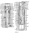
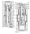
- the fill-up valve assembly 41 is shown in running-in position in Figures 2 and 3 and in circulating or drilling position in Figures 6 and 7. It comprises a gate 41' having a substantially rectangular cross-section and running in a hole 42 which hole is closed at one end by locking nut 45 having a slotted part 46 in communication with a bore 35 in the body part 2.
- a screen 47 covers a recess, formed in outer barrel 1 which is in communication with fill-up channel 36, and an inlet 48 which opens into flappervalve release channel 49.
- Channel 49 extends through inner barrel 2 and opens into circumferential groove 50 formed in plunger housing 26 and ports 51 extend from groove 50 into the plunger cylinders.
- the first purpose of the fill-up valve assembly 41 is to be in open position ( Figure 3) to fill up the drill pipe when running the drill pipe into the hole and simultaneously to close off the flappervalve release channel 49 when running into the hole so that no pressure difference between the annulus.and drillpipe can lift the plungers 25 and accidentally cause the flappervalve 22 to close.
- Its second purpose is to close off the fill-up channel 36 once circulation or drilling has commenced.
- the greater pressure inside the drill pipe is propagated through channel 35 to gate 41 and moves the gate 41 to close the fill-up channel 36, against the lesser pressure in the annulus as shown in Figure 7.
- the gate 41 moves it also closes the fill up channel 36 and mud will fill the fluid lock 52.
- the shut-off sleeve 34 is moved downardly when circulation is started and to increase the pressure drop an aluminium disc 37' with an orifice may be provided by means of threaded ring 37 which disc will be disintegrated during circulation.
- the position is shown in Figure 6.
- shut-off sleeve 34 When the shut-off sleeve 34 moves downwardly against the tension of spring 33, the locking spring snaps into the locking groove 39 formed in the inner wall of inner barrel 2 and shuts off the channels 35 and 36.
- the shut-off sleeve 34 is provided with three pressure equalising channels 40.
- Another purpose of the fill-up valve assembly is to provide the possibility to calibrate the tension of the spring loaded steel ball 23' ( Figure 2) and the spiral spring 29 before running the D.H.BOP into the hole.
- the spring loaded steel ball 23' is there to prevent fluttering of the flapper valve release sleeve 23 by pressures lower than the setting of the spring 29 for releasing the flapper valve 22.
- the fill-up valve gate 41 is set in the drilling position as shown in Figure 7 whereafter a grease pump with a pressure gauge is connected to the threaded inlet 48 leading to flapper valve release channel 49.
- the tension set for the spiral spring 29 depends on the maximum expected penetration rate per hour, the hole size, the depth of the hole, the pump volume and the cross sectional area of the plungers 25.
- the required spring tension is the tension required to overbalance the greater hydrostatic head of the mud column in the annulus caused by the presence of drilled formation cuttings when the pump is stopped.
- a checkvalve 53 is provided to allow mud to enter and to inflate the inflatable packer element 54 when the flappervalve 22 has been released and closed, and the flappervalve sleeve 18 has been pumped down to uncover the inflating port 55. This operation will be described later. Mud can then be pumped through port 55 and channel 56 into packer element 54. The check valve 53 closes and retains the mud in the inflatable packer element 54 when the pressure in the drillpipe drops.
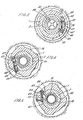
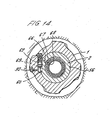
- the outside diameter of the outer barrel 1 has a partly enlarged diameter la, which is provided with spiral grooves 16 ( Figure 4) like an undersized solid body stabilizer.
- the enlarged diameter provides protection for the packer element 54.
- a steel ring 54' at the bottom end of the packer element 54 is connected to the packer sleeve 5 by means of shearpins 54''. This to protect the packer element whilst running into the hole and to withstand rotational forces when drilling.
- the shearpins 54" are sheared when the packer 54 is inflated say at a pressure of 700 psi.
- a shut-off valve assembly 57 is provided which is composed of a shut-off piston 57' with 0-ring seals, a helical pressure spring 58 and a bushing 59 with a thread 59' for a grease nipple.
- shut-off piston 57' When running in and drilling (Figure 5), the shut-off piston 57' is isolated from the pressure inside the tool by the flappervalve sleeve 18 with which is provided O-ring seals ( Figure 2). It is exposed to the pressure inside the tool when in inflating the packer element 54 the flappervalve sleeve 18 is pushed downardly and its friction cam 20 rides over the snapring 17 which then snaps into the slot 21 as will be described later.
- shut-off piston 57' The object of the shut-off piston 57' is to close the channel 60 while pump pressure is present within the tool, and to open the channel 60 when the pump is stopped. This is achieved by the pressure within the tool moving the piston 57' against the spring 58 to close the channel 60 from the annulus.
- An equalising valve 62 is provided ( Figure 5) which comprises an equalising piston 62, having a conical nose, a helical pressure spring 63 and a threaded bushing 64 in which bolt 65 is screwed.
- the purpose of the equalising valve is to open the packer element to the.channel 60 when the pressure in the annulus below the packer (which is fed to the valve via channel 66) is exceeded by 300 psi by the mud pressure which is above the packer.
- the mud pressure is present in channel 60 when piston 57' opens the channel 60 to the annulus.
- equalising piston 62 On the opposite side of the equalising piston 62 the formation pressure below the packer is received via equalising port 64 and aligned ports 67 and 68 formed in flappervalve sleeve 18 and snapring sleeve 13 respectively.
- the overpressure required to move and open the equalising piston 62 can be adjusted by means of the spring loaded ball 84 resting in groove 92 and can be tested with a grease pump having a pressure gauge when the grease nipple is screwed into the thread 57.
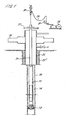
- the D.H.BOP can be run into the hole, so that it reaches eventually the position as shown in Figure 1.
- Figure 1 is shown the D.H.BOP 70, interconnected between the drillpipe-string 71 and drillbit 72 and run into hole 73 so that annulus 74 is formed.
- a casing 75 is cemented in the upper portion 73' of the hole 73, while at the surface a surface.blow out preventer 76 of known type is provided below rotary table 77. Mud can be pumped by.pump 78 through hose 79 and swivel 80 down into drillpipe-string 71, which mud then is ejected from drillbit 72 and flows upwardly through annulus 74.
- a pressure gauge is shown.
- the drillpipe When running in, the drillpipe is empty and the floatvalve 7 is closed and in its highest position (see Figure 2) so that no mud can enter the drillpipe through the bit nozzles and no formation cuttings can settle down inside the bit on top of the bit nozzles causing the bit to become plugged when circulation is started.
- the filling of the drillpipe takes place through the fill-up opening 36 and hole 42 of the fill-up gate 41.
- the floatvalve 7, the valve seat inside body 7' and the valve assembly circumferential body seals should be inspected and be in a good condition or changed for new ones before making-up a new bit.
- shut-off sleeve 34 take out the threaded ring 37 from shut-off sleeve 34 with a set and pulling tool, and screw a set and pulling tool into the same thread and pull the shut-off sleeve 34 up until its highest position unscrew tool and screw in threaded ring 37 again.
- the fill-up valve gate 41 has to be cleaned and to be reset after each roundtrip. Unscrew locking nut 45, put grease nipple in the thread, pump out the housing 44 for gate piston 43 together with the gate 41, clean and reinsert gate 41 and housing 44, use grease, set gate 41 in fill-up position.. with a set bolt "s" and screw in locking nut 45, take out set bolt and tighten locking nut 45.
- the D.H.BOP can be run again and is ready to operate again when necessary.
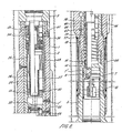
- Figure 8 gives a clear insight of the operation and the position of each valve and part when a kick is encountered and the annulus is closed in by the surface BOP 76.
- the floatvalve assembly. 7 was in its lowest position when circulating. Now the pumps 78 ( Figure 1) are stopped so that the closed floatvalve assembly 7 acts like a floating piston and when pressure below it is building up it can move upwardly making it possible to read the closed in drillpipe pressure (C.I.D.P.P.) from the pressure gauge 81 ( Figure 1).
- the time required for the C.I.D.P.P. to build up should be about ten (10) minutes, depending on the column of gas already produced in the annulus 74 (compression).
- the C.I.D.P.P. is recored and the required mud weight calculated with sufficient overbalance over the formation pore pressure.
- Pump speed is increased to 100-200 gln/min. depending on the size of the D.H.BOP and the size of the circulating channels 59.
- the .flappervalve sleeve 18 snaps with its friction cam 20 over the snapring 17 which is locked in the snapring slot 21 and the packer 52 is set.
- the packer 54 is now isolating the producing zone from the remaining portion of the hole.
- the tool is closed-off at the bottom by the float valve assembly 7 and from the top by the flappervalve 22.
- shut-off piston 57 opens the equalising channel 60.
- the hydrostatic pressure of the mud column above the packer 54 acts on the one side of the equalising piston 62 which normally shuts off deflating channel 69.
- the other side of the equalising piston 62 is connected through channel 66 and ports 67, 68 with the space between the flappervalve 22 and the float valve assembly 7, below which the formation pore pressure acts.
- the equalising piston 62 moves and opens the deflating channel 69.
- the pressure of abt. 1500 psi. behind the packer element 54 is now released in the annulus through channels 69 and 60.and the packer elements deflates and the packer is free.
- Circulating takes then place through the circulating ports instead of through the bit nozzles.
- D.H.BOP Downlink Prediction Protocol
- surface BOP positioned on the sea bed and it is desired to suspend drilling operations e.g. when weather is bad.
- the surface BOP is first closed and the mud pressure within the string is bled down. Mud under pressure is then forced into the annulus whereby the pressure in the annulus exceeds the pressure setting of the arresting ball and helical spring in the tool by at least the amount necessary to operate the D.H.BOP to close the flapper valve.
- the packer element can then be inflated as before and this will seal the bottom end of the casing and the drill string and the surface pipe from the sea bed to the drilling vessel can be removed.
- Reconnecting the surface pipe and the drill pipe and releasing the packer can be achieved by closing the drill pipe at the surface and pressurising the annulus, below the closed BOP rams at the surface, to open the equalising valve, whereafter the rams are opened.
- An advantage of the DHPOP described is that in addition to controlling a well in a novel manner, a well can be brought under control in the conventional manner. In this case on detecting a kick the surface BOP is closed and the closed in drill pipe pressure is read. Instead of lowering the closed in pressure to close the flapper valve, the closed in pressure is maintained. The flapper valve does not close and the well can be brought under control in the normal way by the introduction of heavier mud.
Landscapes
- Engineering & Computer Science (AREA)
- Geology (AREA)
- Mining & Mineral Resources (AREA)
- Life Sciences & Earth Sciences (AREA)
- General Life Sciences & Earth Sciences (AREA)
- Fluid Mechanics (AREA)
- Environmental & Geological Engineering (AREA)
- Physics & Mathematics (AREA)
- Geochemistry & Mineralogy (AREA)
- Mechanical Engineering (AREA)
- Earth Drilling (AREA)
- Centrifugal Separators (AREA)
- Medical Preparation Storing Or Oral Administration Devices (AREA)
- Drilling Tools (AREA)
- Farming Of Fish And Shellfish (AREA)
- Fertilizing (AREA)
- Containers And Packaging Bodies Having A Special Means To Remove Contents (AREA)
- Safety Valves (AREA)
- Acyclic And Carbocyclic Compounds In Medicinal Compositions (AREA)
Priority Applications (1)
| Application Number | Priority Date | Filing Date | Title |
|---|---|---|---|
| AT84300664T ATE25868T1 (de) | 1983-02-04 | 1984-02-02 | Ausblasventil im bohrloch und verfahren zum betrieb eines derartigen ventils. |
Applications Claiming Priority (2)
| Application Number | Priority Date | Filing Date | Title |
|---|---|---|---|
| US46367483A | 1983-02-04 | 1983-02-04 | |
| US463674 | 1983-02-04 |
Publications (2)
| Publication Number | Publication Date |
|---|---|
| EP0116443A1 true EP0116443A1 (de) | 1984-08-22 |
| EP0116443B1 EP0116443B1 (de) | 1987-03-11 |
Family
ID=23840923
Family Applications (1)
| Application Number | Title | Priority Date | Filing Date |
|---|---|---|---|
| EP84300664A Expired EP0116443B1 (de) | 1983-02-04 | 1984-02-02 | Ausblasventil im Bohrloch und Verfahren zum Betrieb eines derartigen Ventils |
Country Status (9)
| Country | Link |
|---|---|
| EP (1) | EP0116443B1 (de) |
| JP (1) | JPS59145893A (de) |
| AT (1) | ATE25868T1 (de) |
| AU (1) | AU2405484A (de) |
| BR (1) | BR8400483A (de) |
| CA (1) | CA1212042A (de) |
| DE (1) | DE3462619D1 (de) |
| NO (1) | NO168131C (de) |
| RO (1) | RO89841A (de) |
Cited By (7)
| Publication number | Priority date | Publication date | Assignee | Title |
|---|---|---|---|---|
| WO1988008917A1 (en) * | 1987-05-14 | 1988-11-17 | Peder Smedvig A/S | Blowout preventer |
| EP0593122A3 (en) * | 1992-10-16 | 1994-06-29 | Norsk Hydro Technology | Blow-out prevention device for shutting off an annulus between a drill column and a well wall |
| WO1997005759A3 (en) * | 1995-08-05 | 1997-04-17 | Clive French | Improved downhole apparatus |
| US6152224A (en) * | 1995-08-05 | 2000-11-28 | French; Clive John | Downhole apparatus |
| WO2009018173A3 (en) * | 2007-07-27 | 2009-04-02 | Weatherford Lamb | Continuous flow drilling systems and methods |
| US9353587B2 (en) | 2011-09-21 | 2016-05-31 | Weatherford Technology Holdings, Llc | Three-way flow sub for continuous circulation |
| US10006262B2 (en) | 2014-02-21 | 2018-06-26 | Weatherford Technology Holdings, Llc | Continuous flow system for drilling oil and gas wells |
Families Citing this family (1)
| Publication number | Priority date | Publication date | Assignee | Title |
|---|---|---|---|---|
| NO325521B1 (no) * | 2006-11-23 | 2008-06-02 | Statoil Asa | Sammenstilling for trykkontroll ved boring og fremgangsmate for trykkontroll ved boring i en formasjon med uforutsett hoyt formasjonstrykk |
Citations (6)
| Publication number | Priority date | Publication date | Assignee | Title |
|---|---|---|---|---|
| US2858838A (en) * | 1955-11-10 | 1958-11-04 | Scaramucci Domer | Drill pipe float valve |
| US3419040A (en) * | 1966-12-27 | 1968-12-31 | Edward J. Thibodeaux | Drill pipe valve having means for rendering it temporarily inoperative |
| US3503445A (en) * | 1968-04-16 | 1970-03-31 | Exxon Production Research Co | Well control during drilling operations |
| US3908769A (en) * | 1973-01-04 | 1975-09-30 | Shell Oil Co | Method and means for controlling kicks during operations in a borehole penetrating subsurface formations |
| US3941190A (en) * | 1974-11-18 | 1976-03-02 | Lynes, Inc. | Well control apparatus |
| US4294314A (en) * | 1979-12-31 | 1981-10-13 | Hydril Company | Inside blowout preventer well tool |
-
1984
- 1984-01-26 RO RO84113422A patent/RO89841A/ro unknown
- 1984-01-31 NO NO840367A patent/NO168131C/no unknown
- 1984-01-31 JP JP59016918A patent/JPS59145893A/ja active Pending
- 1984-02-02 AT AT84300664T patent/ATE25868T1/de not_active IP Right Cessation
- 1984-02-02 DE DE8484300664T patent/DE3462619D1/de not_active Expired
- 1984-02-02 EP EP84300664A patent/EP0116443B1/de not_active Expired
- 1984-02-03 AU AU24054/84A patent/AU2405484A/en not_active Abandoned
- 1984-02-03 CA CA000446732A patent/CA1212042A/en not_active Expired
- 1984-02-03 BR BR8400483A patent/BR8400483A/pt unknown
Patent Citations (6)
| Publication number | Priority date | Publication date | Assignee | Title |
|---|---|---|---|---|
| US2858838A (en) * | 1955-11-10 | 1958-11-04 | Scaramucci Domer | Drill pipe float valve |
| US3419040A (en) * | 1966-12-27 | 1968-12-31 | Edward J. Thibodeaux | Drill pipe valve having means for rendering it temporarily inoperative |
| US3503445A (en) * | 1968-04-16 | 1970-03-31 | Exxon Production Research Co | Well control during drilling operations |
| US3908769A (en) * | 1973-01-04 | 1975-09-30 | Shell Oil Co | Method and means for controlling kicks during operations in a borehole penetrating subsurface formations |
| US3941190A (en) * | 1974-11-18 | 1976-03-02 | Lynes, Inc. | Well control apparatus |
| US4294314A (en) * | 1979-12-31 | 1981-10-13 | Hydril Company | Inside blowout preventer well tool |
Cited By (12)
| Publication number | Priority date | Publication date | Assignee | Title |
|---|---|---|---|---|
| WO1988008917A1 (en) * | 1987-05-14 | 1988-11-17 | Peder Smedvig A/S | Blowout preventer |
| EP0593122A3 (en) * | 1992-10-16 | 1994-06-29 | Norsk Hydro Technology | Blow-out prevention device for shutting off an annulus between a drill column and a well wall |
| US5404953A (en) * | 1992-10-16 | 1995-04-11 | Norsk Hydro A.S. | Blow-out prevention device for shutting off an annulus between a drill column and a well wall when drilling for oil or gas |
| WO1997005759A3 (en) * | 1995-08-05 | 1997-04-17 | Clive French | Improved downhole apparatus |
| US6152224A (en) * | 1995-08-05 | 2000-11-28 | French; Clive John | Downhole apparatus |
| WO2009018173A3 (en) * | 2007-07-27 | 2009-04-02 | Weatherford Lamb | Continuous flow drilling systems and methods |
| US8016033B2 (en) | 2007-07-27 | 2011-09-13 | Weatherford/Lamb, Inc. | Continuous flow drilling systems and methods |
| US8720545B2 (en) | 2007-07-27 | 2014-05-13 | Weatherford/Lamb, Inc. | Continuous flow drilling systems and methods |
| US9151124B2 (en) | 2007-07-27 | 2015-10-06 | Weatherford Technology Holdings, Llc | Continuous flow drilling systems and methods |
| US9353587B2 (en) | 2011-09-21 | 2016-05-31 | Weatherford Technology Holdings, Llc | Three-way flow sub for continuous circulation |
| US10107053B2 (en) | 2011-09-21 | 2018-10-23 | Weatherford Technology Holdings, Llc | Three-way flow sub for continuous circulation |
| US10006262B2 (en) | 2014-02-21 | 2018-06-26 | Weatherford Technology Holdings, Llc | Continuous flow system for drilling oil and gas wells |
Also Published As
| Publication number | Publication date |
|---|---|
| BR8400483A (pt) | 1984-09-11 |
| RO89841A (ro) | 1986-07-30 |
| NO840367L (no) | 1984-08-06 |
| EP0116443B1 (de) | 1987-03-11 |
| NO168131C (no) | 1992-01-15 |
| JPS59145893A (ja) | 1984-08-21 |
| ATE25868T1 (de) | 1987-03-15 |
| NO168131B (no) | 1991-10-07 |
| CA1212042A (en) | 1986-09-30 |
| DE3462619D1 (en) | 1987-04-16 |
| AU2405484A (en) | 1984-08-09 |
Similar Documents
| Publication | Publication Date | Title |
|---|---|---|
| US5499687A (en) | Downhole valve for oil/gas well | |
| US5181571A (en) | Well casing flotation device and method | |
| US5890537A (en) | Wiper plug launching system for cementing casing and liners | |
| US5117915A (en) | Well casing flotation device and method | |
| EP1264076B1 (de) | Mehrzweckschwimmeinrichtung und verfahren | |
| EP0774564B1 (de) | Vorrichtung und Verfahren zum Füllen einer Bohrlochverrohrung | |
| US4986361A (en) | Well casing flotation device and method | |
| US6802372B2 (en) | Apparatus for releasing a ball into a wellbore | |
| US7635026B2 (en) | Methods and devices for forming a wellbore with casing | |
| US6148664A (en) | Method and apparatus for shutting in a well while leaving drill stem in the borehole | |
| US5150756A (en) | Well completion apparatus | |
| US7066281B2 (en) | Formation fluid sampling and hydraulic testing tool and packer assembly therefor | |
| EP1361334A1 (de) | Verfahren und Vorrichtung zur Erhaltung einer Flüssigkeitskolonne in einem Ringraum | |
| US7647973B2 (en) | Collapse arrestor tool | |
| US4588035A (en) | Down hole blow out preventer and method of use | |
| CA2387195A1 (en) | Fill up tool and mud saver for top drives | |
| US4881598A (en) | Blow-out preventor test tool | |
| CA2446868C (en) | Apparatus and method for drilling a wellbore with casing and cementing the casing in the wellbore | |
| EP0116443B1 (de) | Ausblasventil im Bohrloch und Verfahren zum Betrieb eines derartigen Ventils | |
| US4577692A (en) | Pressure operated test valve | |
| CA2065338A1 (en) | Well casing flotation device and method | |
| WO1999022114A1 (en) | Method and apparatus for shutting in a well while leaving drill stem in the borehole | |
| CA1285264C (en) | Downhole device for oil/gas wells | |
| GB2036131A (en) | Valve Assembly for the Remote Control of Fluid Flow with an Automatic Time Delay | |
| AU768260B2 (en) | Method of use and apparatus for a hydraulic tensioning device for inflatable packer element |
Legal Events
| Date | Code | Title | Description |
|---|---|---|---|
| PUAI | Public reference made under article 153(3) epc to a published international application that has entered the european phase |
Free format text: ORIGINAL CODE: 0009012 |
|
| AK | Designated contracting states |
Designated state(s): AT BE CH DE FR GB IT LI LU NL SE |
|
| 17P | Request for examination filed |
Effective date: 19841211 |
|
| RIN1 | Information on inventor provided before grant (corrected) | ||
| RAP1 | Party data changed (applicant data changed or rights of an application transferred) |
Owner name: I.I.E. INNOVATION ENTERPRISE LTD. |
|
| RIN1 | Information on inventor provided before grant (corrected) |
Inventor name: VAN DEN BOOGAART, ABRAHAM Inventor name: VAN GILS, ADRIANUS WILHELMUS |
|
| GRAA | (expected) grant |
Free format text: ORIGINAL CODE: 0009210 |
|
| AK | Designated contracting states |
Kind code of ref document: B1 Designated state(s): AT BE CH DE FR GB IT LI LU NL SE |
|
| PG25 | Lapsed in a contracting state [announced via postgrant information from national office to epo] |
Ref country code: SE Effective date: 19870311 Ref country code: LI Effective date: 19870311 Ref country code: CH Effective date: 19870311 Ref country code: BE Effective date: 19870311 Ref country code: AT Effective date: 19870311 |
|
| REF | Corresponds to: |
Ref document number: 25868 Country of ref document: AT Date of ref document: 19870315 Kind code of ref document: T |
|
| REF | Corresponds to: |
Ref document number: 3462619 Country of ref document: DE Date of ref document: 19870416 |
|
| ITF | It: translation for a ep patent filed | ||
| ET | Fr: translation filed | ||
| REG | Reference to a national code |
Ref country code: CH Ref legal event code: PL |
|
| PLBE | No opposition filed within time limit |
Free format text: ORIGINAL CODE: 0009261 |
|
| STAA | Information on the status of an ep patent application or granted ep patent |
Free format text: STATUS: NO OPPOSITION FILED WITHIN TIME LIMIT |
|
| 26N | No opposition filed | ||
| PG25 | Lapsed in a contracting state [announced via postgrant information from national office to epo] |
Ref country code: LU Free format text: LAPSE BECAUSE OF NON-PAYMENT OF DUE FEES Effective date: 19880229 |
|
| ITPR | It: changes in ownership of a european patent |
Owner name: CESSIONE;I.I.E. INNOVATION ENTERPRISE A/S |
|
| REG | Reference to a national code |
Ref country code: GB Ref legal event code: 732 |
|
| NLS | Nl: assignments of ep-patents |
Owner name: I.I.E. INNOVATION ENTERPRISE A/S TE STAVANGER, NOO |
|
| REG | Reference to a national code |
Ref country code: FR Ref legal event code: TP |
|
| PGFP | Annual fee paid to national office [announced via postgrant information from national office to epo] |
Ref country code: GB Payment date: 19901214 Year of fee payment: 8 |
|
| PGFP | Annual fee paid to national office [announced via postgrant information from national office to epo] |
Ref country code: FR Payment date: 19901221 Year of fee payment: 8 |
|
| ITTA | It: last paid annual fee | ||
| PGFP | Annual fee paid to national office [announced via postgrant information from national office to epo] |
Ref country code: NL Payment date: 19910228 Year of fee payment: 8 |
|
| PGFP | Annual fee paid to national office [announced via postgrant information from national office to epo] |
Ref country code: DE Payment date: 19910423 Year of fee payment: 8 |
|
| PG25 | Lapsed in a contracting state [announced via postgrant information from national office to epo] |
Ref country code: GB Effective date: 19920202 |
|
| PG25 | Lapsed in a contracting state [announced via postgrant information from national office to epo] |
Ref country code: NL Effective date: 19920901 |
|
| GBPC | Gb: european patent ceased through non-payment of renewal fee | ||
| NLV4 | Nl: lapsed or anulled due to non-payment of the annual fee | ||
| PG25 | Lapsed in a contracting state [announced via postgrant information from national office to epo] |
Ref country code: FR Effective date: 19921030 |
|
| PG25 | Lapsed in a contracting state [announced via postgrant information from national office to epo] |
Ref country code: DE Effective date: 19921103 |
|
| REG | Reference to a national code |
Ref country code: FR Ref legal event code: ST |