EP0116486A1 - Elektronischer Regler für die Zuführung von elektrischer Leistung zu einer Vorrichtung zur Temperaturänderung - Google Patents
Elektronischer Regler für die Zuführung von elektrischer Leistung zu einer Vorrichtung zur Temperaturänderung Download PDFInfo
- Publication number
- EP0116486A1 EP0116486A1 EP84400028A EP84400028A EP0116486A1 EP 0116486 A1 EP0116486 A1 EP 0116486A1 EP 84400028 A EP84400028 A EP 84400028A EP 84400028 A EP84400028 A EP 84400028A EP 0116486 A1 EP0116486 A1 EP 0116486A1
- Authority
- EP
- European Patent Office
- Prior art keywords
- temperature
- electronic controller
- detector
- controller according
- memory
- Prior art date
- Legal status (The legal status is an assumption and is not a legal conclusion. Google has not performed a legal analysis and makes no representation as to the accuracy of the status listed.)
- Granted
Links
- 230000033001 locomotion Effects 0.000 claims abstract description 63
- 230000006870 function Effects 0.000 claims abstract description 14
- 238000001514 detection method Methods 0.000 claims description 19
- 230000033228 biological regulation Effects 0.000 claims description 6
- 238000004378 air conditioning Methods 0.000 claims description 5
- 230000008859 change Effects 0.000 claims description 4
- 238000009423 ventilation Methods 0.000 claims description 4
- 230000001360 synchronised effect Effects 0.000 claims 1
- 238000010438 heat treatment Methods 0.000 abstract description 19
- 230000001105 regulatory effect Effects 0.000 abstract description 6
- 230000035945 sensitivity Effects 0.000 abstract description 6
- 230000001276 controlling effect Effects 0.000 abstract description 2
- 230000001419 dependent effect Effects 0.000 abstract description 2
- 238000012545 processing Methods 0.000 description 61
- 230000007704 transition Effects 0.000 description 9
- 238000010586 diagram Methods 0.000 description 8
- 238000005070 sampling Methods 0.000 description 7
- 238000004364 calculation method Methods 0.000 description 5
- 230000003321 amplification Effects 0.000 description 4
- 238000000034 method Methods 0.000 description 4
- 238000003199 nucleic acid amplification method Methods 0.000 description 4
- 230000005540 biological transmission Effects 0.000 description 2
- 238000012937 correction Methods 0.000 description 2
- 238000002955 isolation Methods 0.000 description 2
- 239000004065 semiconductor Substances 0.000 description 2
- 230000006641 stabilisation Effects 0.000 description 2
- 238000011105 stabilization Methods 0.000 description 2
- 238000012360 testing method Methods 0.000 description 2
- 230000008542 thermal sensitivity Effects 0.000 description 2
- 238000006677 Appel reaction Methods 0.000 description 1
- 235000016068 Berberis vulgaris Nutrition 0.000 description 1
- 241000335053 Beta vulgaris Species 0.000 description 1
- 241001415961 Gaviidae Species 0.000 description 1
- 230000009471 action Effects 0.000 description 1
- 230000003213 activating effect Effects 0.000 description 1
- 238000004458 analytical method Methods 0.000 description 1
- 230000008901 benefit Effects 0.000 description 1
- 230000002457 bidirectional effect Effects 0.000 description 1
- 239000013078 crystal Substances 0.000 description 1
- 230000002950 deficient Effects 0.000 description 1
- 238000013461 design Methods 0.000 description 1
- 230000000694 effects Effects 0.000 description 1
- 238000005265 energy consumption Methods 0.000 description 1
- 238000005516 engineering process Methods 0.000 description 1
- 238000000605 extraction Methods 0.000 description 1
- 238000009434 installation Methods 0.000 description 1
- 239000004973 liquid crystal related substance Substances 0.000 description 1
- 238000004519 manufacturing process Methods 0.000 description 1
- 239000000463 material Substances 0.000 description 1
- 229910052751 metal Inorganic materials 0.000 description 1
- 239000002184 metal Substances 0.000 description 1
- 150000002739 metals Chemical class 0.000 description 1
- 238000012986 modification Methods 0.000 description 1
- 230000004048 modification Effects 0.000 description 1
- 230000010355 oscillation Effects 0.000 description 1
- 230000002688 persistence Effects 0.000 description 1
- 230000004044 response Effects 0.000 description 1
- 230000002207 retinal effect Effects 0.000 description 1
- XLYOFNOQVPJJNP-UHFFFAOYSA-N water Substances O XLYOFNOQVPJJNP-UHFFFAOYSA-N 0.000 description 1
Images



Classifications
-
- G—PHYSICS
- G05—CONTROLLING; REGULATING
- G05D—SYSTEMS FOR CONTROLLING OR REGULATING NON-ELECTRIC VARIABLES
- G05D23/00—Control of temperature
- G05D23/19—Control of temperature characterised by the use of electric means
- G05D23/1902—Control of temperature characterised by the use of electric means characterised by the use of a variable reference value
-
- F—MECHANICAL ENGINEERING; LIGHTING; HEATING; WEAPONS; BLASTING
- F24—HEATING; RANGES; VENTILATING
- F24D—DOMESTIC- OR SPACE-HEATING SYSTEMS, e.g. CENTRAL HEATING SYSTEMS; DOMESTIC HOT-WATER SUPPLY SYSTEMS; ELEMENTS OR COMPONENTS THEREFOR
- F24D19/00—Details
- F24D19/10—Arrangement or mounting of control or safety devices
- F24D19/1006—Arrangement or mounting of control or safety devices for water heating systems
- F24D19/1009—Arrangement or mounting of control or safety devices for water heating systems for central heating
-
- F—MECHANICAL ENGINEERING; LIGHTING; HEATING; WEAPONS; BLASTING
- F24—HEATING; RANGES; VENTILATING
- F24D—DOMESTIC- OR SPACE-HEATING SYSTEMS, e.g. CENTRAL HEATING SYSTEMS; DOMESTIC HOT-WATER SUPPLY SYSTEMS; ELEMENTS OR COMPONENTS THEREFOR
- F24D19/00—Details
- F24D19/10—Arrangement or mounting of control or safety devices
- F24D19/1096—Arrangement or mounting of control or safety devices for electric heating systems
-
- G—PHYSICS
- G05—CONTROLLING; REGULATING
- G05D—SYSTEMS FOR CONTROLLING OR REGULATING NON-ELECTRIC VARIABLES
- G05D23/00—Control of temperature
- G05D23/19—Control of temperature characterised by the use of electric means
- G05D23/1917—Control of temperature characterised by the use of electric means using digital means
Definitions
- the present invention relates to an automatic control system for the heating installation in a residential environment.
- An electronic controller makes it possible to automatically regulate the temperature in each room of the residence according to whether said room is occupied or not and / or lit or not.
- thermostat Welker al US Patent 2,873,368 These thermostats, placed in the various rooms of the residence have a limited thermal sensitivity.
- Another method of thermal regulation sometimes suggested is to lower the preset temperature of the thermostat before the user leaves his residence and to restore the nominal temperature as soon as the user returns to his residence.
- Such a method in fact saves on heating energy.
- it has the disadvantage of not being automatic.
- the user is reluctant to use this method because he prefers to enter his residence when it is already warmed up to the nominal temperature.
- the disadvantages described above can be overcome by using an electronic temperature detector and an electronic temperature regulator which allow increased thermal sensitivity and thermal stability, thus ensuring better comfort for the user.
- a motion detector and a light detector are arranged in the various rooms of the residence so as to be able to save on heating energy when said detectors detect neither movement nor light. In this way, the thermal regulation is carried out automatically without the need to adjust the temperature during the entire period of use of the heating system.
- a microcomputer ensures rapid adjustment and stabilization at new temperatures by means of a proportional-integral-differential type control, which determines the average heating power of the heating elements in the room of the residence.
- the invention allows a highly sensitive temperature control system, automated, quickly stabilized and having a definite advantage from the point of view of energy consumption.
- the microcomputer regulates the temperature to the preset values by means of a proportional-integral-differential type controller, which provides control signals as a function of the preset temperatures and the ambient temperature of the room in the residence. signals control the average heating power of the heating elements in the room of the residence.
- the problem to be solved by the present invention consists in designing an electronic temperature controller which on the one hand is provided with better stability and better temperature sensitivity and is designed to operate at predetermined temperature regimes while depending of the presence of occupants and / or the presence of lighting in each room of the residence and which on the other hand allows to regulate the tempé erasing automatically and saving heating energy when the rooms in the residence are unoccupied and / or unlit.
- Such an electronic controller can also be used as an electronic thermometer, alarm system, fire detector or can control any energy device such as a ventilation system, air conditioning, or humidity control during a change in the occupation of the room or in the lighting of the room.
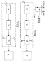
- a light detector 3 which transmits to said digital processing unit 2 the state of lighting of the room.
- a temperature detector 4 which transmits to said digital processing unit 2 the reading of the ambient temperature.
- the state of the system represents the one of the following four possibilities: presence of movement12 in the room and lighting 13 of the room, T1, absence of movement 14 in the room and lighting 13 of the room, T2, presence of movement 12 in the room and darkness 15 of the room , T3, and lack of movement14 in the room and darkness of the room, T4.
- An emergency power supply unit 6 which maintains the preselected temperature values in the memory of the digital processing unit 2 in the event of a mains power failure 56.
- a main power unit 8 which makes it possible to obtain the regulated voltages from the AC power source of the sector 56 in order to power the amplifiers and the digital circuits used or other types of circuit (to all the units 57).
- a zero detector 7 of the mains supply 56 which makes it possible to build a time base for the digital processing unit 2, said time base being used to build the various counters used in the within the digital processing unit 2.
- module "1" located on a wall of the room
- module "2” located on the radiator cover plate
- the motion detector 16 operating on the principle of the Doppler effect, on the principle of variations in the standing wave ratio of waves emitted by an antenna, on the principle of infrared detection, on the principle of photoelectric cells, or on the principle of activating a relay, and which supplies the digital processing unit 2 with binary information relating to the presence or absence of movement in the room.
- the motion detector unit 1 comprises a motion detector 16 using an electromagnetic or ultrasonic emission source and provided with an adjustable transmission power.
- the output signal corresponding to the presence or absence of movement in the room of the residence passes through an amplifier 17 of adjustable gain and through an adjustable threshold detector VS and VT, which determine the sensitivity of the detection system, the threshold detector 18 controlling a flip-flop whose binary output state represents the state of occupation of the room, said binary state being routed to the digital processing unit 2.
- the amplification can be a digital amplification.
- the adjustable digital levels of said thresholds can be determined by potentiometers, the voltage readings of which pass through an analog-digital converter.
- digital processing unit can also be stored in the digital processing unit, a control of additional digital increments on the control panel being able to vary said digital levels which are compared to the digital level of the output signal of the amplifier by means logic circuits, to determine the transitions of the state of the system, which trigger a flip-flop whose output levels represent the state of occupation of the room.
- digital sequence comparator circuits corresponding to successive samples of the motion detector output signal can be used to detect the transitions of the state of the system.
- a light detector 3 comprising a sensor 19 (photosensitive resistance or phototransistor) whose sensitivity is adjustable and whose electrical output signal which depends on the lighting state passes through an adjustable gain amplifier 20 and a hysteresis comparator 21 with two adjustable reference voltages VX and VY, so as to avoid oscillations in the case of Corposcuro.
- the output of the hysteresis comparator 21 is routed to the digital processing unit 2.
- FIG. 5 represents the hysteresis curve of the hysteresis comparator, the thresholds VX and VY of which determine the binary states of output 22 and 23.
- the reference voltages VX and VY may possibly be equal if, however, the reading of the lighting state or the changes in the set points of the controller which delivers a control signal to the temperature variation device as a function of the current temperature and temperature values preset in memory are done at spaced intervals.
- a temperature detector 4 which comprises a thermal sensor 24 (thermistor, semiconductor device or the like) having a sensitivity of x mV / ° C and the output of which is connected via an isolation unit to a amplifier 25 of gain G, the output of which supplies an analog-digital converter 26 which can be incorporated in the digital processing unit 2.
- a command or control signal from the latter 27 synchronizes the transmission of digital information or data 28 from the analog-digital converter 26.
- the adjustable gain G as well as two adjustable reference voltages of the analog-digital converter 26, make it possible to determine the minimum and maximum temperatures of the controller as well that the temperature sensitivity is Gx mV / ° C, which can be translated into an appropriate number of bits / ° C.
- the control panel of the temperature control system 5 comprises two control keys 29 and 30 which determine within a rocker system 31 the selection of the state of the system as well as the desired increment, control signals 32 from the digital processing unit 2 making it possible to read these two pieces of information sequentially.
- the predetermined temperature information corresponding to the states of the system T1, T2, T3 and T4 can be adjusted by means of a potentiometer or be incremented digitally before being stored in the memory of an interface unit.
- display 33 This conveys the data 34 for selecting the current state of the system and performs decoding and amplification operations to supply the display data 35 to the display board 36.
- Control signals 32 and 37 allow the display of the preset temperatures and the state of the corresponding system on the display panel 36.
- the display panel 41 can include, for example, light-emitting diodes, or a gas or preferably liquid crystal display.
- the selection of the state of the system 38 and 39 and the corresponding temperature 40 appear on a display panel 41 in alphanumeric form, the letters or the numbers being sequentially illuminated so that the retinal persistence of the user allows continuous viewing of said letters or numbers.
- An additional indicator 42 may be mounted if the display is one of p room temperature.
- An example of simple control from the point of view of the user consists in ensuring that the temperature readings 40 are incremented as long as the user maintains his finger on the increment key 29, and the control key of selection 30 is activated, while the system state selection readings 38 and 39 are represented each time the user selects the selection control key 30.
- the latter may order the successive display of 40, 38, 39 and 40, 38, 39, 40 and 42, 42 or even no display.
- selection control key 30 remains pressed indefinitely, it is possible to provide automatic return to the display of the ambient temperature after a period of time fixed in advance.
- increment control key 29 is pressed without the selection control key 30 being pressed, it is possible to provide the display: preset temperature corresponding to the state of the current system.
- An emergency power supply unit 6 comprising an automatic charger 43 for a battery 44, which power a second emergency regulator 45, which is used to power the memory cicuits of the digital processing unit 2.
- the battery 44 is connected to the back-up regulator 45 in the event that the mains power source 56 is absent and the main switch of the temperature control system is actuated.
- the automatic charger 43 acts so that the battery is charged when its voltage 46 drops below a first threshold and that the battery charge ceases when the battery voltage exceeds one second. d threshold.
- another threshold detector located in the emergency regulator stops supplying the memory circuits of the digital processing unit.
- An additional protection consists in preventing the battery from being discharged in the automatic charger 46, by means of a diode 47 for example.
- a digital processing unit 2 which can be made up of logic units, microprocessors, a microcomputer or a minicomputer, and which regularly compares the current temperature and the desired temperature with a view to carrying out a correction of PID type (proportional-integral-differential) of the difference between these temperatures.
- the output signal u (t) from the PID controller is a function of the input signal e (t) as follows: where the constants K, T i and T d are chosen so as to optimize the response of the temperature regulator in terms of rise time, overshoot, stabilization time and steady state.
- the digital processing unit 2 delivers a control signal which determines the number of cycles per second during which the radiator is in operation. This number of cycles can vary from 0% to 100% of a certain number of cycles of the main power source.
- the control signal of the digital processing unit can be a series of pulses which can be processed to form a series of analog modulated pulses (pulse modulation in height, pulse modulation in position or pulse modulation in duration), which is transmitted to the power control unit 10.
- the pulse modulated in duration passes through a current amplifier 50 within the module "1" 51, then is electrically transmitted to an isolation unit 52 - follower amplifier 54, or preferably an electro-optical isolator located in the power control unit 10 within the module “2" 48 and supplies the trigger of a power switch such as a relay or a semiconductor power switch - triac 55, SCR, or other - connected, in series to radiator 9, to sector 56.
- a power switch such as a relay or a semiconductor power switch - triac 55, SCR, or other - connected, in series to radiator 9, to sector 56.
- the digital processing unit uses time bases derived from a crystal oscillator and not from a zero detector 7 of sector 56
- a zero detector of the sector sector 56 in the power control unit 10 within the module "2" 48.
- the zero detector output pulses will be used to trigger a first power switch which is biased by the duration-modulated pulse from the digital processing unit 2 and the output of which is used to trigger a second power switch connected, in series to the radiator 9, to sector 56.
- Additional interface circuits are optionally added in order to make the digital processing unit 2 compatible from the point of view of transistor / CMOS technologies with the display interface unit 33, with the motion detection unit 1, the light detector 3, the temperature detector 4, the control panel 5, the zero detector 7 and the power control unit 10.
- the same power switch can activate several radiators in parallel; several radiators independent can be actuated by several power switches which are controlled by the pulse modulated in duration coming from the digital processing unit 2.
- the digital processing unit 2 can be a microcomputer having two working states, the processing state and the preselection state: in processing state, the system takes the information relating to the different detectors, and makes the necessary calculations for control the power control circuit 10.
- the microcomputer goes to the preselection state, state in which the signals routed to the power control circuit 10 are those which preexisted before the actuation of the selection control keys 30 and of incrementation 29.
- the microcomputer switches from the preselection state to the state after a specified period of time, after which all of the microcomputer timers are reset.
- the microcomputer software includes two main routines.
- the first routine performs the following operations: control of the power control unit 10, control of the motion detection unit 1, control of the light detector 3, control of the temperature detector 4, request to display new data , each of said checks being able to be sampled at times determined by appropriate counters, and calculation of the terms of the equation of the proportional-integral-differential regulator.
- the second routine performs the following operations: initialization of the working variables, initialization of a binary test value in the memory of the microcomputer in order to check the emergency power supply 6 of the microcomputer, control of the increment key 29, control of the selection key '30 and initialization of a period of time for affichage.des transistions of the system state.
- the preselected temperature values are kept in a defined portion of the memory which is supplied by the battery 44. In this way, the system can resume processing operations. However, the system will carry out a check of a test value placed in the memory of the microcomputer in order to prevent a loss of the preserved values, which can be caused by a defective beet. In such a case, the temperature control system will adjust to a determined temperature value regardless of the state of the system, until the programmable memory is updated. Said determined temperature value can be used to initialize the counters of the system when the temperature control system is activated.
- a regulating counter 59 decides the calculation times of the regulating unit 58 of the proportional, proportional-integral or proportional-integral-differential type. This counter also decides the sampling times of the ambient temperature values within the analog-digital converter associated with the temperature detector 4.
- a power meter 57 which is decremented during the duration of the pulse modulated in duration associated with the output of the regulator 58.
- f s being the frequency of the sector 56 and k a constant
- the radiator 9 will be actuated for a duration of where x can vary from 0 to 2f s .
- x can vary from 0 to 2f s .
- k (1 - 2f s ) will represent the time during which the radiator 9 is off.
- the radiator 9 is switched via the power control unit 10.
- the regulator counter 59 is subordinated to the expiration of the standby counter 60, in order to allow a calculation of the regulator on new preselected values during the transition from the preselection state to the processing state.
- the wait counter 60 is initialized when the digital processing unit changes from the preselection state to the processing state. During the transition from the processing state to the preselection state, the power counter 57 continues to operate at the value x which existed in the processing state, until the new calculation of the output values of the regulator 58 which follows the complete decrementing of the waiting counter 60.
- the sampling counter 61 of the motion detector unit 1 decides successive read times of the binary state associated with the motion detector unit 1.
- the motion counter 62 is initialized following a motion detection within a motion processing unit 63 associated with the motion detector 1.
- This motion processing unit 63 associated with the motion detection makes it possible to change by means of a pointer register 64, the temperature serving as a set point for the system, which is located in the random access memory unit 65.
- the initialization value of the movement counter 62 depends on the binary state associated with the light detector 3.
- the information of the binary state associated with the light detector 3 arrives via the motion processing unit 63 and the light sampling counter 66.
- the set point corresponding to the state of the system T 1 is maintained for a duration Y, which begins to be measured when the movement detection in the room stops.
- the corresponding set point laying in the state of the system T 3 is maintained for a period Z, which begins to be measured when the movement detection in the room stops.
- the light sampling counter 66 decides the intervals separating the successive readings from the binary state associated with the light detector 3, which readings are transmitted to the pointer register 64 which decides which of the temperature values preselected in memory 65, serves as setpoint at regulator 58.
- the display counter 67 determines when the data of the display circuits is updated.
- the display is renewed every Q seconds.
- the display is modified after a delay of R seconds in order to allow the user to observe on the display panel the changes in the system state, while pointer register 64 is updated instantly.
- the increment control button 29 When the increment control button 29 is pressed while the digital processing unit is in the processing state, the temperature serving as the current set point is displayed for a duration S.
- the control button increment 29 initiates via the rocker system 31, the display processing unit 68, and the selection processing unit 71, the extraction of the predetermined temperature serving as a set point for the regulator 58, said temperature being extracted from the RAM unit 65 via the pointer register 64 before being routed to the display unit 11.
- any action of the increment key 29 initiates a flip-flop 31 which initializes an increment ring counter 69 which, once decremented, will activate the increment unit 70.
- the increment counter 69 is reset as long as the user presses the key increment 29.
- the increment processing unit 70 updates the memory 65 and, moreover, updates the display unit 11 via the display processing unit 68 .
- the selection control key 30 When passing from the preselection state to the processing state, the selection control key 30 initiates the flip-flop 31, which initializes the waiting counter 60, and moreover transmits via the processing unit. display 68 the new ambient temperature data at the display unit 11.
- the selection control key 30 When changing from the processing state to the preselecting state, the selection control key 30 initiates the flip-flop 31 which uses the preselected values temperature stored in the memory 65 through the selection processing unit 71, the display processing unit 68, the selection processing unit 71 and the pointer register 64.
- a monostable 72 is actuated each time the selection control 30 or incrementation 29 key is actuated. At the end of the monostable output pulse, the digital processing unit returns to the processing state. This is to avoid that the system does not remain in the preselection state continuously in the event that the user forgets to return the digital processing unit to the processing state.
- the emergency power supply 6 ensures the conversation of the temperature values preselected in memory 65 in the event of a power failure 56.
- time base unit B 1 73 which can be determined directly from the alternative power source of the sector 56 by means of a Zero detector 7 of said sector power supply.
- This time base can be by example where f represents the frequency of the sector 56.
- a second time base of a second 74 (second counter) and a minute 75 (minute counter) can be deduced from the time base B 1 73.
- the following counters could be associated with the time base B,: sampling counter 61 of the motion detection unit and power counter 57.
- the time base of one second will be used by the following counters: counter display 67, regulating counter 59, incrementing counter 69.
- the one minute time base will be used by the following counters: sampling counters 66 of the light detector, movement counter 62 and standby counter 60.
- the duration of said counters can be fixed in advance in a read-only memory or even be adjusted by means of potentiometers whose output voltage level is digitally translated by means of an analog-to-digital converter.
- a detector of the transitions of the state of the system located within the digital processing unit is used to prime, defuse, or even enslave a power control circuit of the ventilation system.
- the transition detectors are electrically connected to the relay of an alarm system, said system will be activated during the transitions from T2 or T4 to T1 or T3.
- Another example would be the control of a humidifier when a transition from T4 to T3 is detected.
- the temperature controller as a fire detector. To do this, it is sufficient to check whether the ambient temperature exceeds a determined high threshold beyond a time delay.
- each state of operation comprising memorizable preselected values, so that the user can use his system in special cases such as for example that of large rooms.
- the system will offer, in addition to the normal operating state option, one or more additional options of the user's choice.
- the system described here can be used to control a central heating system of the on-off type by installing motion and / or light detectors at key locations. It can also be used to control the temperature in each room through the engine control actuating the hot water or hot air pipe valves. It can also be used to activate by means of a simple relay the ventilation or air conditioning system in the given room, the name on-off can refer to both a central heating system and a system of air conditioning; standard corrections of the humidity setting according to the temperature can be incorporated into the system in order to adjust the humidity in a residence according to the ambient temperature.
Landscapes
- Engineering & Computer Science (AREA)
- Physics & Mathematics (AREA)
- Combustion & Propulsion (AREA)
- Automation & Control Theory (AREA)
- Thermal Sciences (AREA)
- Chemical & Material Sciences (AREA)
- General Physics & Mathematics (AREA)
- Mechanical Engineering (AREA)
- General Engineering & Computer Science (AREA)
- Circuit Arrangement For Electric Light Sources In General (AREA)
- Control Of Temperature (AREA)
- Domestic Hot-Water Supply Systems And Details Of Heating Systems (AREA)
- Air Conditioning Control Device (AREA)
Priority Applications (1)
| Application Number | Priority Date | Filing Date | Title |
|---|---|---|---|
| AT84400028T ATE59911T1 (de) | 1983-01-07 | 1984-01-06 | Elektronischer regler fuer die zufuehrung von elektrischer leistung zu einer vorrichtung zur temperaturaenderung. |
Applications Claiming Priority (2)
| Application Number | Priority Date | Filing Date | Title |
|---|---|---|---|
| CA419062 | 1983-01-07 | ||
| CA000419062A CA1171938A (fr) | 1983-01-07 | 1983-01-07 | Controleur automatique de temperature, de chauffage d'air conditionne et d'humidite sensible au mouvement et a la lumiere |
Publications (2)
| Publication Number | Publication Date |
|---|---|
| EP0116486A1 true EP0116486A1 (de) | 1984-08-22 |
| EP0116486B1 EP0116486B1 (de) | 1991-01-09 |
Family
ID=4124281
Family Applications (1)
| Application Number | Title | Priority Date | Filing Date |
|---|---|---|---|
| EP84400028A Expired - Lifetime EP0116486B1 (de) | 1983-01-07 | 1984-01-06 | Elektronischer Regler für die Zuführung von elektrischer Leistung zu einer Vorrichtung zur Temperaturänderung |
Country Status (5)
| Country | Link |
|---|---|
| US (1) | US4623969A (de) |
| EP (1) | EP0116486B1 (de) |
| AT (1) | ATE59911T1 (de) |
| CA (1) | CA1171938A (de) |
| DE (1) | DE3483890D1 (de) |
Cited By (4)
| Publication number | Priority date | Publication date | Assignee | Title |
|---|---|---|---|---|
| FR2590381A1 (fr) * | 1985-11-15 | 1987-05-22 | Electro Mec Nivernais | Thermostat electronique |
| EP0222957A1 (de) * | 1985-11-14 | 1987-05-27 | APPLICATIONS ET RECHERCHES ELECTROTECHNIQUES AVANCEES A.R.E.A. Société Anonyme Monégasque: | Regelungseinrichtung für elektrische Beheizung |
| GB2345554A (en) * | 1999-01-08 | 2000-07-12 | Norman Maurice Harmer | Electrical heating apparatus with selectable thermostat control |
| FR3031167A1 (fr) * | 2014-12-24 | 2016-07-01 | Atlantic Soc Fr De Developpement Thermique | Procede de gestion d'installation de chauffage et installation de chauffage correspondante |
Families Citing this family (28)
| Publication number | Priority date | Publication date | Assignee | Title |
|---|---|---|---|---|
| US4730941A (en) * | 1985-03-08 | 1988-03-15 | Honeywell Inc. | Temperature range display device for electronic thermostat |
| JPS62280533A (ja) * | 1986-05-28 | 1987-12-05 | Daikin Ind Ltd | 空気調和機の室温制御装置 |
| JPS63294449A (ja) * | 1987-02-20 | 1988-12-01 | Yuukiyan Kk | 超音波加湿器による加湿制御装置 |
| CA1294326C (fr) * | 1988-05-24 | 1992-01-14 | David Bensoussan | Controleur electronique alimente pendant les periodes inactives de commutation du secteur |
| US5105366A (en) * | 1990-05-03 | 1992-04-14 | Honeywell Inc. | Comfort control system and method factoring mean radiant temperature |
| US5280422A (en) * | 1990-11-05 | 1994-01-18 | Watlow/Winona, Inc. | Method and apparatus for calibrating and controlling multiple heaters |
| US5127575A (en) * | 1991-04-15 | 1992-07-07 | Beerbaum Ronald H | Supervisory control unit for electrical equipment |
| US5192020A (en) * | 1991-11-08 | 1993-03-09 | Honeywell Inc. | Intelligent setpoint changeover for a programmable thermostat |
| DE4303153A1 (de) * | 1993-02-01 | 1994-08-04 | Eberhard Dr Schwarzer | Steuereinrichtung für einen Wärmetauscher |
| US5285961A (en) * | 1993-02-11 | 1994-02-15 | Rodriguez Jr Jose A | Thermostat control system |
| US5289094A (en) * | 1993-02-22 | 1994-02-22 | Young Charles C | Light responsive airflow register |
| US5344068A (en) * | 1993-04-16 | 1994-09-06 | Staefa Control System, Inc. | Dynamically controlled environmental control system |
| US5566879A (en) * | 1993-12-06 | 1996-10-22 | Comptel Domotique Inc. | System for centralized controlling of a plurality of temperature regulating devices |
| US5444436A (en) * | 1993-12-29 | 1995-08-22 | Kennison; Ricky R. | Furnace and air conditioner failure alarm apparatus |
| US6243028B1 (en) * | 1996-12-13 | 2001-06-05 | Agenor Krygler | Parking meter |
| SE0003112D0 (sv) * | 2000-09-04 | 2000-09-04 | Granqvist Claes Goeran | Climate control system and method for controlling such |
| US7302642B2 (en) * | 2003-06-03 | 2007-11-27 | Tim Simon, Inc. | Thermostat with touch-screen display |
| US20050014496A1 (en) * | 2003-07-14 | 2005-01-20 | Seung-Jae Han | Method and apparatus for adaptive and online assignment in hierarchical overlay networks |
| US7196295B2 (en) * | 2003-11-21 | 2007-03-27 | Watlow Electric Manufacturing Company | Two-wire layered heater system |
| US20060196953A1 (en) * | 2005-01-19 | 2006-09-07 | Tim Simon, Inc. | Multiple thermostat installation |
| US7802618B2 (en) * | 2005-01-19 | 2010-09-28 | Tim Simon, Inc. | Thermostat operation method and apparatus |
| US7894943B2 (en) | 2005-06-30 | 2011-02-22 | Sloup Charles J | Real-time global optimization of building setpoints and sequence of operation |
| US8108075B2 (en) * | 2009-05-22 | 2012-01-31 | R.W. Beckett Corporation | Failsafe HVAC control upgrades |
| CN101905363A (zh) * | 2009-06-03 | 2010-12-08 | 鸿富锦精密工业(深圳)有限公司 | 电烙铁 |
| US8209066B2 (en) * | 2010-02-11 | 2012-06-26 | Bae Systems Information And Electronic Systems Integration Inc. | Environmental control system for precision airborne payloads |
| US8482162B2 (en) * | 2010-05-03 | 2013-07-09 | Kulite Semiconductor Products, Inc. | Two lead electronic switch system adapted to replace a mechanical switch system |
| US20140257588A1 (en) * | 2013-03-06 | 2014-09-11 | LifeSmart Electronics, LLC | Appliance Shut-Off Device and Method |
| FR3045307B1 (fr) * | 2015-12-17 | 2017-12-29 | Atlantic Industrie Sas | Appareil de chauffage, de preference de type seche-serviette, pour le chauffage d'une salle de bain |
Citations (12)
| Publication number | Priority date | Publication date | Assignee | Title |
|---|---|---|---|---|
| US2873368A (en) * | 1955-05-03 | 1959-02-10 | Barber Colman Co | Electrical control apparatus |
| CA1035448A (en) * | 1976-04-26 | 1978-07-25 | Emerson Electric Co. | Timer controlled space thermostat with battery operated timer |
| FR2395671A1 (fr) * | 1977-06-21 | 1979-01-19 | Mecelec Sa | Perfectionnements au reglage des installations de chauffage electrique |
| US4200910A (en) * | 1977-03-04 | 1980-04-29 | Hall Burness C | Programmable time varying control system and method |
| DE2855227A1 (de) * | 1978-12-21 | 1980-06-26 | Honeywell Gmbh | Verfahren zum optimieren des energieverbrauches in gebaeuden sowie anordnung zur durchfuehrung des verfahrens |
| US4284126A (en) * | 1979-07-05 | 1981-08-18 | Dawson N Rick | Environmental control system for a multiple room structure |
| US4294404A (en) * | 1978-02-14 | 1981-10-13 | Integrated Energy Systems | Environmental control system |
| FR2483579A1 (fr) * | 1980-06-02 | 1981-12-04 | Csea Consorzio Sviluppo Elettr | Dispositif de reglage et de controle d'une installation pour le rechauffage de l'air ambiant |
| CA1114474A (en) * | 1979-12-11 | 1981-12-15 | Michael R. Levine | Electronic thermostat |
| CA1117625A (en) * | 1978-01-11 | 1982-02-02 | Gim Wong | Electronic timer and thermoswitch device |
| FR2491692A1 (fr) * | 1980-10-08 | 1982-04-09 | Honeywell Inc | Dispositif d'alimentation auxiliaire par batterie |
| WO1982002608A1 (en) * | 1981-01-20 | 1982-08-05 | Miles Terrance Allen | Control system for energy consuming installation |
Family Cites Families (8)
| Publication number | Priority date | Publication date | Assignee | Title |
|---|---|---|---|---|
| CA741463A (en) | 1966-08-23 | Barber-Colman Company | Condition controlling system | |
| US4095740A (en) | 1976-04-01 | 1978-06-20 | Wirth Jon C | Condition responsive thermostat control apparatus |
| DE2704565A1 (de) | 1977-02-03 | 1978-08-10 | Sick Optik Elektronik Erwin | Photoelektronisches geraet |
| FR2432255A2 (fr) * | 1978-05-22 | 1980-02-22 | Ardissone Jacques | Installation de chauffage electrique |
| FR2427025A1 (fr) * | 1978-05-22 | 1979-12-21 | Ardissone Jacques | Installation de chauffage electrique |
| US4316256A (en) | 1979-12-31 | 1982-02-16 | Microcomm Corporation | Thermostat with automatic heat/air conditioning changeover |
| US4433809A (en) | 1980-03-12 | 1984-02-28 | Schulz Daniel R | Controller for air conditioning or heating system |
| DE3176096D1 (en) | 1981-11-12 | 1987-05-14 | Delta Dore | Room thermostat device with a day-time programmer |
-
1983
- 1983-01-07 CA CA000419062A patent/CA1171938A/fr not_active Expired
-
1984
- 1984-01-05 US US06/568,392 patent/US4623969A/en not_active Expired - Fee Related
- 1984-01-06 EP EP84400028A patent/EP0116486B1/de not_active Expired - Lifetime
- 1984-01-06 DE DE8484400028T patent/DE3483890D1/de not_active Expired - Lifetime
- 1984-01-06 AT AT84400028T patent/ATE59911T1/de not_active IP Right Cessation
Patent Citations (12)
| Publication number | Priority date | Publication date | Assignee | Title |
|---|---|---|---|---|
| US2873368A (en) * | 1955-05-03 | 1959-02-10 | Barber Colman Co | Electrical control apparatus |
| CA1035448A (en) * | 1976-04-26 | 1978-07-25 | Emerson Electric Co. | Timer controlled space thermostat with battery operated timer |
| US4200910A (en) * | 1977-03-04 | 1980-04-29 | Hall Burness C | Programmable time varying control system and method |
| FR2395671A1 (fr) * | 1977-06-21 | 1979-01-19 | Mecelec Sa | Perfectionnements au reglage des installations de chauffage electrique |
| CA1117625A (en) * | 1978-01-11 | 1982-02-02 | Gim Wong | Electronic timer and thermoswitch device |
| US4294404A (en) * | 1978-02-14 | 1981-10-13 | Integrated Energy Systems | Environmental control system |
| DE2855227A1 (de) * | 1978-12-21 | 1980-06-26 | Honeywell Gmbh | Verfahren zum optimieren des energieverbrauches in gebaeuden sowie anordnung zur durchfuehrung des verfahrens |
| US4284126A (en) * | 1979-07-05 | 1981-08-18 | Dawson N Rick | Environmental control system for a multiple room structure |
| CA1114474A (en) * | 1979-12-11 | 1981-12-15 | Michael R. Levine | Electronic thermostat |
| FR2483579A1 (fr) * | 1980-06-02 | 1981-12-04 | Csea Consorzio Sviluppo Elettr | Dispositif de reglage et de controle d'une installation pour le rechauffage de l'air ambiant |
| FR2491692A1 (fr) * | 1980-10-08 | 1982-04-09 | Honeywell Inc | Dispositif d'alimentation auxiliaire par batterie |
| WO1982002608A1 (en) * | 1981-01-20 | 1982-08-05 | Miles Terrance Allen | Control system for energy consuming installation |
Cited By (5)
| Publication number | Priority date | Publication date | Assignee | Title |
|---|---|---|---|---|
| EP0222957A1 (de) * | 1985-11-14 | 1987-05-27 | APPLICATIONS ET RECHERCHES ELECTROTECHNIQUES AVANCEES A.R.E.A. Société Anonyme Monégasque: | Regelungseinrichtung für elektrische Beheizung |
| FR2590381A1 (fr) * | 1985-11-15 | 1987-05-22 | Electro Mec Nivernais | Thermostat electronique |
| EP0229540A1 (de) * | 1985-11-15 | 1987-07-22 | Societe Electromecanique De Nevers Selnev | Elektronischer Thermostat |
| GB2345554A (en) * | 1999-01-08 | 2000-07-12 | Norman Maurice Harmer | Electrical heating apparatus with selectable thermostat control |
| FR3031167A1 (fr) * | 2014-12-24 | 2016-07-01 | Atlantic Soc Fr De Developpement Thermique | Procede de gestion d'installation de chauffage et installation de chauffage correspondante |
Also Published As
| Publication number | Publication date |
|---|---|
| DE3483890D1 (de) | 1991-02-14 |
| EP0116486B1 (de) | 1991-01-09 |
| US4623969A (en) | 1986-11-18 |
| ATE59911T1 (de) | 1991-01-15 |
| CA1171938A (fr) | 1984-07-31 |
Similar Documents
| Publication | Publication Date | Title |
|---|---|---|
| EP0116486B1 (de) | Elektronischer Regler für die Zuführung von elektrischer Leistung zu einer Vorrichtung zur Temperaturänderung | |
| EP3404334B1 (de) | Energiespeicherverfahren und -anlage, die einen wasserboiler umfasst | |
| CA1294326C (fr) | Controleur electronique alimente pendant les periodes inactives de commutation du secteur | |
| FR2483579A1 (fr) | Dispositif de reglage et de controle d'une installation pour le rechauffage de l'air ambiant | |
| EP3467605B1 (de) | Überwachungsverfahren eines systems zur temperaturregulierung, das zu einem schaltschrank gehört | |
| FR2923604A1 (fr) | Procede et systeme de correction en boucle ouverte du gradient vertical d'un four d'etalonnage a puits sec | |
| FR2513405A1 (fr) | Dispositif de commande d'une unite de changement de temperature de l'air | |
| FR2657418A1 (fr) | Systeme regulateur pour une installation de chauffage d'eau marchant de preference au gaz. | |
| FR2879853A1 (fr) | Appareil et procede d'attribution de puissance electrique | |
| EP3181025B1 (de) | Heizvorrichtung, bevorzugt ein handtuchtrockner, zur heizung eines badezimmers | |
| FR2505597A1 (fr) | Dispositif pour determiner sans sonde la temperature d'une cuisiniere | |
| WO2017051140A1 (fr) | Système climatique apte à réaliser des alertes techniques | |
| EP0181259B1 (de) | Verfahren und Vorrichtung zur Ermittlung des Wärmeverbrauches der einzelnen Verbraucher in einem zentral geheizten Gebäude | |
| CN105093978A (zh) | 传感器装置和关联方法 | |
| EP2902762A1 (de) | Verfahren zur Bestimmung einer Wärmesignatur eines Gebäudes durch Temperaturmessung im Zeitverlauf, und entsprechende Vorrichtung | |
| EP0852331B1 (de) | Verfahren zur Messung des Volumenkoeffizienten von Wärmeverlusten eines elektrisch geheizten Raumes | |
| EP1884854B1 (de) | Vorrichtung zum Beheizen von Räumen | |
| FR2536877A1 (fr) | Procede et dispositif de programmation, de regulation, de controle d'economie du fonctionnement d'une installation de chauffage | |
| JP7645664B2 (ja) | 浴室暖房乾燥システム | |
| FR3031167A1 (fr) | Procede de gestion d'installation de chauffage et installation de chauffage correspondante | |
| FR3040092A1 (fr) | Dispositif electronique permettant la commande d'un chauffage electrique utilisant un capteur de temperature influence par les elements chauffants | |
| FR2569257A1 (fr) | Dispositif de regulation cybernetique d'energie | |
| FR2836760A1 (fr) | Systeme de surveillance et de commande d'une armoire de distribution | |
| FR3067483A1 (fr) | Procede de detection de presence d'individus | |
| FR2593276A1 (fr) | Systeme de programmation et de controle automatique de la temperature interieure de locaux individuels tels que par exemple des appartements |
Legal Events
| Date | Code | Title | Description |
|---|---|---|---|
| PUAI | Public reference made under article 153(3) epc to a published international application that has entered the european phase |
Free format text: ORIGINAL CODE: 0009012 |
|
| AK | Designated contracting states |
Designated state(s): AT BE CH DE FR GB IT LI LU NL SE |
|
| 17P | Request for examination filed |
Effective date: 19850220 |
|
| 17Q | First examination report despatched |
Effective date: 19861218 |
|
| RAP3 | Party data changed (applicant data changed or rights of an application transferred) |
Owner name: TARDIO, DON Owner name: BENSOUSSAN, DAVID |
|
| GRAA | (expected) grant |
Free format text: ORIGINAL CODE: 0009210 |
|
| AK | Designated contracting states |
Kind code of ref document: B1 Designated state(s): AT BE CH DE FR GB IT LI LU NL SE |
|
| PG25 | Lapsed in a contracting state [announced via postgrant information from national office to epo] |
Ref country code: SE Effective date: 19910109 Ref country code: NL Effective date: 19910109 Ref country code: IT Free format text: LAPSE BECAUSE OF FAILURE TO SUBMIT A TRANSLATION OF THE DESCRIPTION OR TO PAY THE FEE WITHIN THE PRESCRIBED TIME-LIMIT;WARNING: LAPSES OF ITALIAN PATENTS WITH EFFECTIVE DATE BEFORE 2007 MAY HAVE OCCURRED AT ANY TIME BEFORE 2007. THE CORRECT EFFECTIVE DATE MAY BE DIFFERENT FROM THE ONE RECORDED. Effective date: 19910109 Ref country code: AT Effective date: 19910109 |
|
| REF | Corresponds to: |
Ref document number: 59911 Country of ref document: AT Date of ref document: 19910115 Kind code of ref document: T |
|
| REF | Corresponds to: |
Ref document number: 3483890 Country of ref document: DE Date of ref document: 19910214 |
|
| GBT | Gb: translation of ep patent filed (gb section 77(6)(a)/1977) | ||
| NLV1 | Nl: lapsed or annulled due to failure to fulfill the requirements of art. 29p and 29m of the patents act | ||
| PLBE | No opposition filed within time limit |
Free format text: ORIGINAL CODE: 0009261 |
|
| STAA | Information on the status of an ep patent application or granted ep patent |
Free format text: STATUS: NO OPPOSITION FILED WITHIN TIME LIMIT |
|
| 26N | No opposition filed | ||
| PG25 | Lapsed in a contracting state [announced via postgrant information from national office to epo] |
Ref country code: LU Free format text: LAPSE BECAUSE OF NON-PAYMENT OF DUE FEES Effective date: 19920131 Ref country code: BE Effective date: 19920131 |
|
| BERE | Be: lapsed |
Owner name: TARDIO DON Effective date: 19920131 Owner name: BENSOUSSAN DAVID Effective date: 19920131 |
|
| PGFP | Annual fee paid to national office [announced via postgrant information from national office to epo] |
Ref country code: GB Payment date: 19931231 Year of fee payment: 11 |
|
| PGFP | Annual fee paid to national office [announced via postgrant information from national office to epo] |
Ref country code: CH Payment date: 19940103 Year of fee payment: 11 |
|
| PGFP | Annual fee paid to national office [announced via postgrant information from national office to epo] |
Ref country code: FR Payment date: 19940128 Year of fee payment: 11 |
|
| PGFP | Annual fee paid to national office [announced via postgrant information from national office to epo] |
Ref country code: DE Payment date: 19940130 Year of fee payment: 11 |
|
| PG25 | Lapsed in a contracting state [announced via postgrant information from national office to epo] |
Ref country code: GB Effective date: 19950106 |
|
| PG25 | Lapsed in a contracting state [announced via postgrant information from national office to epo] |
Ref country code: LI Effective date: 19950131 Ref country code: CH Effective date: 19950131 |
|
| GBPC | Gb: european patent ceased through non-payment of renewal fee |
Effective date: 19950106 |
|
| PG25 | Lapsed in a contracting state [announced via postgrant information from national office to epo] |
Ref country code: FR Effective date: 19950929 |
|
| REG | Reference to a national code |
Ref country code: CH Ref legal event code: PL |
|
| PG25 | Lapsed in a contracting state [announced via postgrant information from national office to epo] |
Ref country code: DE Effective date: 19951003 |
|
| REG | Reference to a national code |
Ref country code: FR Ref legal event code: ST |