EP0116525A2 - Bauweise für ein isolierendes Dach zur Befestigung einer aussenwandig gewellten Dachplatte, vorzugsweise aus Metallblech - Google Patents
Bauweise für ein isolierendes Dach zur Befestigung einer aussenwandig gewellten Dachplatte, vorzugsweise aus Metallblech Download PDFInfo
- Publication number
- EP0116525A2 EP0116525A2 EP84850044A EP84850044A EP0116525A2 EP 0116525 A2 EP0116525 A2 EP 0116525A2 EP 84850044 A EP84850044 A EP 84850044A EP 84850044 A EP84850044 A EP 84850044A EP 0116525 A2 EP0116525 A2 EP 0116525A2
- Authority
- EP
- European Patent Office
- Prior art keywords
- shaped portions
- groove
- insulation
- securing
- securing members
- Prior art date
- Legal status (The legal status is an assumption and is not a legal conclusion. Google has not performed a legal analysis and makes no representation as to the accuracy of the status listed.)
- Granted
Links
- 239000002184 metal Substances 0.000 title claims description 8
- 238000009413 insulation Methods 0.000 claims abstract description 30
- 238000010276 construction Methods 0.000 claims 6
- 239000000463 material Substances 0.000 description 5
- 238000010079 rubber tapping Methods 0.000 description 2
- 241001661918 Bartonia Species 0.000 description 1
- 230000006978 adaptation Effects 0.000 description 1
- 230000006835 compression Effects 0.000 description 1
- 238000007906 compression Methods 0.000 description 1
- 239000003365 glass fiber Substances 0.000 description 1
- 239000003292 glue Substances 0.000 description 1
- XLYOFNOQVPJJNP-UHFFFAOYSA-N water Substances O XLYOFNOQVPJJNP-UHFFFAOYSA-N 0.000 description 1
Images
Classifications
-
- E—FIXED CONSTRUCTIONS
- E04—BUILDING
- E04D—ROOF COVERINGS; SKY-LIGHTS; GUTTERS; ROOF-WORKING TOOLS
- E04D3/00—Roof covering by making use of flat or curved slabs or stiff sheets
- E04D3/36—Connecting; Fastening
- E04D3/3607—Connecting; Fastening the fastening means comprising spacer means adapted to the shape of the profiled roof covering
-
- E—FIXED CONSTRUCTIONS
- E04—BUILDING
- E04D—ROOF COVERINGS; SKY-LIGHTS; GUTTERS; ROOF-WORKING TOOLS
- E04D3/00—Roof covering by making use of flat or curved slabs or stiff sheets
- E04D3/24—Roof covering by making use of flat or curved slabs or stiff sheets with special cross-section, e.g. with corrugations on both sides, with ribs, flanges, or the like
- E04D3/30—Roof covering by making use of flat or curved slabs or stiff sheets with special cross-section, e.g. with corrugations on both sides, with ribs, flanges, or the like of metal
Definitions
- This invention relates to a system intended for securing a pre-shaped thin-walled external roofing, which is supported on a layer of medium-hard insulation, on an underlying carrying roof structure supporting the insulation layer, which system has the form of a strip.
- battens of some kind are provided on the same support (usually sectional sheets), which carries the insulation. These battens are secured on the support and carry the external roofing,
- fastening members comprise a cone-shaped body and a self-tapping screw extending therefrom. Said cone-shaped body co-operates with the hard insulation while the self-tapping screw
- the external roofing material usually is roofing felt, which is fixed with glue on the hard insulation.
- the two aforesaid roof structures have certain economic disadvantages.
- the roof structure with soft insulation comprises special battens for supporting the roofing which, of course, renders the structure more expensive.
- the roof structure with hard insulation it
- the present invention has the object to provide a system for securing the external roofing, by means of which system it is possible to use relatively cheap medium-
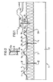
- Fig. 1 shows an embodiment of a roof structure, to which the system according to the invention is applied and Fig. 2 is a section along II-II in Fig. 1.
- the roof shown in Fig. 1 comprises lowermost a carrying structure 1, which at the embodiment shown is a self--supporting sectional metal sheet with an embossed upper flange 2 and high webs 3.
- the carrying roof structure extends between primary girders (not shown) with a spaced c/c-relationship of 6-12 m.
- the primary girders thus, extend in the direction of the pitch.
- an insulation layer 4 is attached above the roof structure 1.
- the insulation usually is of so-called medium-hard type.
- a plurality of supporting strips 5 are arranged with a spaced relationship of 2-3 m.
- the supporting strips 5 extend across the pitch direction.
- the supporting strip 5 includes a portion 5a abutting the insulation.
- the cross-section of said portion appears from Fig. 2, i.e. said portion includes a central longitudinal groove recessed about 10-15 mm.
- the grooved portions 5a are connected by a crest-shaped portion 5b, the configuration of which has space in the configuration of the external roofing and at least in some part joins to said portion.
- the supporting strips 5 are jointed in that two grooved portions 5a overlap one another.
- the supporting strips 5 are secured in such a way, that screws 6 are passed through pre-drilled holes in the bottom of the grooved portion 5a, and a lower threaded portion 6a of the screw 6 is caused to engage with the upper flange 2 of the self-supporting sectional metal sheet.
- the screw 6 is threaded in to such a depth that the screw head 6b abuts the bottom of the grooved portions 5a.
- the holes are located directly above each other when the supporting strips are being jointed.
- the supporting strips 5 are now secured against being lifted, but downward movement along the screws 6 can -s take place, because the pre-drilled holes have a diameter slightly exceeding that of the screw stem.
- the external roofing 7 in the form of a sectional metal sheet is attached.
- the sectional sheet 7 comprises a plurality of crest portions 7b, which are connected by intermediate, substantially plane portions 7b, which are provided with embossments 8a and 8b extending both longitudinally and transversely.
- the crest portions 7a extend in the direction of the pitch and are provided with a longitudinal stiffening groove 9.
- the sheet 7 has in one lateral edge a groove 10, which collects water possibly leaking in and drains it.
- the sheet is secured on the supporting strips 5, in that fastening members 11, preferably screws, extend through the highermost located portions of the sheet 7 and supporting strips 5.
- the maximum distance, through which the sheet 7 can be moved downward, corresponds to the depth of the grooved portion 5a. At further downward movement of the sheet 7, the screw head 6b will deform said sheet. However, the grooved portion 5a having a depth of about 15 mm, there is safe margin preventing the screw head 6b from contacting the portion 7b of the external roof sheet 7.
- medium-hard insulation also ensures limitation of the compression due to snow load.
- the carrying roof structure consists as stated above of sectional metal sheet with wide upper flange and high webs. It also can be imagined, however, to use a stiffened trapezoid sectional sheet as carrying structure. In order to avoid too high a load, at lifting forces, on the upper flange carrying the supporting strip, it is also imaginable within the scope of the invention to arrange the supporting strips so as to run diagonally over the trapezoid sectional sheet. This requires adaptation of the measures and angles of the strip.
- a special sectional metal sheet is used as external roofing material.
- corrugated sheets of other materials for example plastic, glass fibre etc. as roofing material.
Landscapes
- Engineering & Computer Science (AREA)
- Architecture (AREA)
- Civil Engineering (AREA)
- Structural Engineering (AREA)
- Mechanical Engineering (AREA)
- Roof Covering Using Slabs Or Stiff Sheets (AREA)
- Tents Or Canopies (AREA)
- Radar Systems Or Details Thereof (AREA)
- Ultra Sonic Daignosis Equipment (AREA)
- Bridges Or Land Bridges (AREA)
Priority Applications (1)
| Application Number | Priority Date | Filing Date | Title |
|---|---|---|---|
| AT84850044T ATE52562T1 (de) | 1983-02-10 | 1984-02-08 | Bauweise fuer ein isolierendes dach zur befestigung einer aussenwandig gewellten dachplatte, vorzugsweise aus metallblech. |
Applications Claiming Priority (2)
| Application Number | Priority Date | Filing Date | Title |
|---|---|---|---|
| SE8300717 | 1983-02-10 | ||
| SE8300717A SE444833B (sv) | 1983-02-10 | 1983-02-10 | Anordning vid isolerat yttertak for forankring av en takteckning av plat samt yttertakkonstruktion forsedd med denna anordning |
Publications (3)
| Publication Number | Publication Date |
|---|---|
| EP0116525A2 true EP0116525A2 (de) | 1984-08-22 |
| EP0116525A3 EP0116525A3 (en) | 1985-12-11 |
| EP0116525B1 EP0116525B1 (de) | 1990-05-09 |
Family
ID=20349982
Family Applications (1)
| Application Number | Title | Priority Date | Filing Date |
|---|---|---|---|
| EP84850044A Expired - Lifetime EP0116525B1 (de) | 1983-02-10 | 1984-02-08 | Bauweise für ein isolierendes Dach zur Befestigung einer aussenwandig gewellten Dachplatte, vorzugsweise aus Metallblech |
Country Status (7)
| Country | Link |
|---|---|
| US (1) | US4590728A (de) |
| EP (1) | EP0116525B1 (de) |
| AT (1) | ATE52562T1 (de) |
| DE (1) | DE3482196D1 (de) |
| FI (1) | FI80939C (de) |
| SE (1) | SE444833B (de) |
| WO (1) | WO1984003118A1 (de) |
Cited By (2)
| Publication number | Priority date | Publication date | Assignee | Title |
|---|---|---|---|---|
| FR2706981A1 (de) * | 1993-06-23 | 1994-12-30 | Stramit Corp Ltd | |
| US5636488A (en) * | 1993-06-23 | 1997-06-10 | Stramit Corporation Limited | Panel and clip arrangement |
Families Citing this family (4)
| Publication number | Priority date | Publication date | Assignee | Title |
|---|---|---|---|---|
| FR2676244B1 (fr) * | 1991-05-07 | 1994-01-28 | Francis Ovaert | Structure composite, notamment pour le batiment. |
| US5855101A (en) * | 1993-07-23 | 1999-01-05 | Nci Building Systems, Inc. | Apparatus for retrofitting a metal roof |
| US5402572A (en) * | 1993-07-23 | 1995-04-04 | Nci Building Systems, L.P. | Apparatus and method for retrofitting a metal roof |
| US5842316A (en) * | 1998-02-05 | 1998-12-01 | Keiper; Timothy John | Roof panel mounting system |
Family Cites Families (15)
| Publication number | Priority date | Publication date | Assignee | Title |
|---|---|---|---|---|
| US2105280A (en) * | 1937-06-26 | 1938-01-11 | John M Bass | Reinforcement |
| US2325124A (en) * | 1942-03-25 | 1943-07-27 | William R Gardner | Weather surface covering |
| GB819047A (en) * | 1957-01-01 | 1959-08-26 | Fred Pedley | Improvements in construction of roofing |
| US3031044A (en) * | 1957-11-04 | 1962-04-24 | R C Mahon Company | Fire retardant wall construction |
| FR1237309A (fr) * | 1959-06-19 | 1960-07-29 | Commerciale Du Cuivre Soc Ind | étrier continu pour la pose de panneaux de couverture autoportants |
| US3038573A (en) * | 1959-08-14 | 1962-06-12 | Aluminum Co Of America | Corrugated sheathing systems |
| GB1290000A (de) * | 1968-10-02 | 1972-09-20 | ||
| DE2256584C3 (de) * | 1971-11-22 | 1980-10-30 | Otto Zambelli Pty. Ltd., Brunswick, Victoria (Australien) | Dacheindeckung |
| FR2313517A1 (fr) * | 1975-06-04 | 1976-12-31 | Duraffourg Jean | Couverture isolante a double paroi |
| NL7606219A (en) * | 1976-06-09 | 1977-12-13 | Atlas Stone Company Limited | Insulated roof with upper asbestos cement sheets - has glass fibre layer trapped between spacers and light panels underneath |
| SE414954B (sv) * | 1977-06-21 | 1980-08-25 | Plannja Ab | Skarv mellan tva korrugerade takplatar |
| US4250678A (en) * | 1979-04-30 | 1981-02-17 | Transco, Inc. | Mounting for insulated panel |
| US4329823A (en) * | 1979-11-13 | 1982-05-18 | Encon Products, Inc. | Support spacer apparatus |
| US4516371A (en) * | 1979-11-13 | 1985-05-14 | Encon Products, Inc. | Insulation and paneling apparatus and method |
| US4348846A (en) * | 1980-10-02 | 1982-09-14 | Butler Manufacturing Company | Insulated roof |
-
1983
- 1983-02-10 SE SE8300717A patent/SE444833B/sv not_active IP Right Cessation
-
1984
- 1984-02-08 DE DE8484850044T patent/DE3482196D1/de not_active Expired - Lifetime
- 1984-02-08 US US06/662,409 patent/US4590728A/en not_active Expired - Fee Related
- 1984-02-08 WO PCT/SE1984/000040 patent/WO1984003118A1/en not_active Ceased
- 1984-02-08 AT AT84850044T patent/ATE52562T1/de not_active IP Right Cessation
- 1984-02-08 EP EP84850044A patent/EP0116525B1/de not_active Expired - Lifetime
- 1984-10-10 FI FI843983A patent/FI80939C/fi not_active IP Right Cessation
Cited By (2)
| Publication number | Priority date | Publication date | Assignee | Title |
|---|---|---|---|---|
| FR2706981A1 (de) * | 1993-06-23 | 1994-12-30 | Stramit Corp Ltd | |
| US5636488A (en) * | 1993-06-23 | 1997-06-10 | Stramit Corporation Limited | Panel and clip arrangement |
Also Published As
| Publication number | Publication date |
|---|---|
| SE8300717D0 (sv) | 1983-02-10 |
| WO1984003118A1 (en) | 1984-08-16 |
| EP0116525B1 (de) | 1990-05-09 |
| EP0116525A3 (en) | 1985-12-11 |
| FI843983L (fi) | 1984-10-10 |
| FI80939C (fi) | 1990-08-10 |
| FI80939B (fi) | 1990-04-30 |
| FI843983A0 (fi) | 1984-10-10 |
| SE8300717L (sv) | 1984-08-11 |
| US4590728A (en) | 1986-05-27 |
| DE3482196D1 (de) | 1990-06-13 |
| ATE52562T1 (de) | 1990-05-15 |
| SE444833B (sv) | 1986-05-12 |
Similar Documents
| Publication | Publication Date | Title |
|---|---|---|
| US4672785A (en) | Modified runner and area separation wall structure utilizing runner | |
| FI78334C (fi) | Taktaeckningsplaot. | |
| US4446665A (en) | Insulated roof structure system and method of erecting same | |
| US4382353A (en) | Reverse furring technique | |
| US8024906B1 (en) | Standing-seam roof assembly bracket | |
| CA2085499A1 (en) | Building panel assembly | |
| US4914886A (en) | Device for laying out profiled sheet | |
| US3091313A (en) | Long span deck member | |
| US4741139A (en) | Prefabricated building panel | |
| US6185889B1 (en) | Flat style roof drainage system and low point column head | |
| EP0116525A2 (de) | Bauweise für ein isolierendes Dach zur Befestigung einer aussenwandig gewellten Dachplatte, vorzugsweise aus Metallblech | |
| US3289360A (en) | Fabricated folded plate roof structure and support therefor | |
| US4087949A (en) | Building of improved cardboard panel construction | |
| SE448390B (sv) | Yttertakkonstruktion | |
| WO2000053859A1 (en) | Method and arrangement for assembling roof | |
| JPS63293261A (ja) | 屋根材 | |
| GB2182960A (en) | Insulated roof | |
| SU1560458A1 (ru) | Подкранова балка | |
| SE501387C2 (sv) | Takelement samt ett förfarande för dess montering | |
| NO160730B (no) | Anordning for feste et korrugert/profilert, tynnryggeksternt tak, samt yttertak konstruksjon som baerer et slikt eksternt tak. | |
| CA1240472A (en) | Prefabricated building panel | |
| EP0401438A1 (de) | Dacheindeckungen | |
| JPS5930099Y2 (ja) | 大型山形屋根 | |
| AU700471B2 (en) | Roof framing system | |
| JP2840225B2 (ja) | 屋根の構造 |
Legal Events
| Date | Code | Title | Description |
|---|---|---|---|
| PUAI | Public reference made under article 153(3) epc to a published international application that has entered the european phase |
Free format text: ORIGINAL CODE: 0009012 |
|
| AK | Designated contracting states |
Designated state(s): AT BE CH DE FR GB IT LI NL |
|
| 17P | Request for examination filed |
Effective date: 19850214 |
|
| PUAL | Search report despatched |
Free format text: ORIGINAL CODE: 0009013 |
|
| AK | Designated contracting states |
Designated state(s): AT BE CH DE FR GB IT LI NL |
|
| 17Q | First examination report despatched |
Effective date: 19871008 |
|
| GRAA | (expected) grant |
Free format text: ORIGINAL CODE: 0009210 |
|
| AK | Designated contracting states |
Kind code of ref document: B1 Designated state(s): AT BE CH DE FR GB IT LI NL |
|
| REF | Corresponds to: |
Ref document number: 52562 Country of ref document: AT Date of ref document: 19900515 Kind code of ref document: T |
|
| REF | Corresponds to: |
Ref document number: 3482196 Country of ref document: DE Date of ref document: 19900613 |
|
| ITF | It: translation for a ep patent filed | ||
| ET | Fr: translation filed | ||
| PGFP | Annual fee paid to national office [announced via postgrant information from national office to epo] |
Ref country code: AT Payment date: 19910212 Year of fee payment: 8 |
|
| PGFP | Annual fee paid to national office [announced via postgrant information from national office to epo] |
Ref country code: BE Payment date: 19910213 Year of fee payment: 8 |
|
| PGFP | Annual fee paid to national office [announced via postgrant information from national office to epo] |
Ref country code: CH Payment date: 19910221 Year of fee payment: 8 |
|
| PGFP | Annual fee paid to national office [announced via postgrant information from national office to epo] |
Ref country code: FR Payment date: 19910227 Year of fee payment: 8 |
|
| ITTA | It: last paid annual fee | ||
| PGFP | Annual fee paid to national office [announced via postgrant information from national office to epo] |
Ref country code: NL Payment date: 19910228 Year of fee payment: 8 |
|
| PLBE | No opposition filed within time limit |
Free format text: ORIGINAL CODE: 0009261 |
|
| STAA | Information on the status of an ep patent application or granted ep patent |
Free format text: STATUS: NO OPPOSITION FILED WITHIN TIME LIMIT |
|
| 26N | No opposition filed | ||
| PG25 | Lapsed in a contracting state [announced via postgrant information from national office to epo] |
Ref country code: AT Effective date: 19920208 |
|
| PG25 | Lapsed in a contracting state [announced via postgrant information from national office to epo] |
Ref country code: BE Effective date: 19920228 |
|
| PG25 | Lapsed in a contracting state [announced via postgrant information from national office to epo] |
Ref country code: LI Effective date: 19920229 Ref country code: CH Effective date: 19920229 |
|
| BERE | Be: lapsed |
Owner name: PLANNJA A.B. Effective date: 19920228 |
|
| PG25 | Lapsed in a contracting state [announced via postgrant information from national office to epo] |
Ref country code: NL Effective date: 19920901 |
|
| NLV4 | Nl: lapsed or anulled due to non-payment of the annual fee | ||
| PG25 | Lapsed in a contracting state [announced via postgrant information from national office to epo] |
Ref country code: FR Effective date: 19921030 |
|
| REG | Reference to a national code |
Ref country code: CH Ref legal event code: PL |
|
| REG | Reference to a national code |
Ref country code: FR Ref legal event code: ST |
|
| PGFP | Annual fee paid to national office [announced via postgrant information from national office to epo] |
Ref country code: DE Payment date: 19960430 Year of fee payment: 13 |
|
| PGFP | Annual fee paid to national office [announced via postgrant information from national office to epo] |
Ref country code: GB Payment date: 19970130 Year of fee payment: 14 |
|
| PG25 | Lapsed in a contracting state [announced via postgrant information from national office to epo] |
Ref country code: DE Effective date: 19971101 |
|
| PG25 | Lapsed in a contracting state [announced via postgrant information from national office to epo] |
Ref country code: GB Free format text: LAPSE BECAUSE OF NON-PAYMENT OF DUE FEES Effective date: 19980208 |
|
| GBPC | Gb: european patent ceased through non-payment of renewal fee |
Effective date: 19980208 |