EP0116920A1 - Appareil de chauffage à diaphragme pour réchauffer des liquides - Google Patents
Appareil de chauffage à diaphragme pour réchauffer des liquides Download PDFInfo
- Publication number
- EP0116920A1 EP0116920A1 EP84101385A EP84101385A EP0116920A1 EP 0116920 A1 EP0116920 A1 EP 0116920A1 EP 84101385 A EP84101385 A EP 84101385A EP 84101385 A EP84101385 A EP 84101385A EP 0116920 A1 EP0116920 A1 EP 0116920A1
- Authority
- EP
- European Patent Office
- Prior art keywords
- distributor
- air
- heater according
- heater
- chambers
- Prior art date
- Legal status (The legal status is an assumption and is not a legal conclusion. Google has not performed a legal analysis and makes no representation as to the accuracy of the status listed.)
- Withdrawn
Links
- 239000007788 liquid Substances 0.000 title abstract description 7
- 238000010438 heat treatment Methods 0.000 title description 6
- 229910010293 ceramic material Inorganic materials 0.000 claims abstract description 5
- 239000007789 gas Substances 0.000 claims description 14
- 238000005192 partition Methods 0.000 claims description 6
- 239000002737 fuel gas Substances 0.000 claims description 3
- 229910052751 metal Inorganic materials 0.000 abstract description 13
- 239000002184 metal Substances 0.000 abstract description 13
- 239000003795 chemical substances by application Substances 0.000 abstract description 8
- 239000000446 fuel Substances 0.000 abstract description 5
- 238000007747 plating Methods 0.000 abstract description 5
- 239000004449 solid propellant Substances 0.000 abstract description 4
- 238000005246 galvanizing Methods 0.000 description 6
- 238000000034 method Methods 0.000 description 6
- 238000002485 combustion reaction Methods 0.000 description 5
- 230000008569 process Effects 0.000 description 5
- 239000003245 coal Substances 0.000 description 3
- 230000009467 reduction Effects 0.000 description 3
- 239000007790 solid phase Substances 0.000 description 3
- 229910000831 Steel Inorganic materials 0.000 description 2
- HCHKCACWOHOZIP-UHFFFAOYSA-N Zinc Chemical compound [Zn] HCHKCACWOHOZIP-UHFFFAOYSA-N 0.000 description 2
- 238000005260 corrosion Methods 0.000 description 2
- 230000007797 corrosion Effects 0.000 description 2
- 230000000694 effects Effects 0.000 description 2
- 239000007787 solid Substances 0.000 description 2
- 239000010959 steel Substances 0.000 description 2
- 229910052725 zinc Inorganic materials 0.000 description 2
- 239000011701 zinc Substances 0.000 description 2
- OKTJSMMVPCPJKN-UHFFFAOYSA-N Carbon Chemical compound [C] OKTJSMMVPCPJKN-UHFFFAOYSA-N 0.000 description 1
- XEEYBQQBJWHFJM-UHFFFAOYSA-N Iron Chemical compound [Fe] XEEYBQQBJWHFJM-UHFFFAOYSA-N 0.000 description 1
- 238000005054 agglomeration Methods 0.000 description 1
- 230000002776 aggregation Effects 0.000 description 1
- 239000004411 aluminium Substances 0.000 description 1
- 229910052782 aluminium Inorganic materials 0.000 description 1
- XAGFODPZIPBFFR-UHFFFAOYSA-N aluminium Chemical compound [Al] XAGFODPZIPBFFR-UHFFFAOYSA-N 0.000 description 1
- 238000005269 aluminizing Methods 0.000 description 1
- QVGXLLKOCUKJST-UHFFFAOYSA-N atomic oxygen Chemical compound [O] QVGXLLKOCUKJST-UHFFFAOYSA-N 0.000 description 1
- 230000008901 benefit Effects 0.000 description 1
- 229910052799 carbon Inorganic materials 0.000 description 1
- 239000003575 carbonaceous material Substances 0.000 description 1
- 239000003054 catalyst Substances 0.000 description 1
- 239000000567 combustion gas Substances 0.000 description 1
- -1 ferrous metals Chemical class 0.000 description 1
- 230000004907 flux Effects 0.000 description 1
- 238000009434 installation Methods 0.000 description 1
- 238000004519 manufacturing process Methods 0.000 description 1
- 238000002844 melting Methods 0.000 description 1
- 230000008018 melting Effects 0.000 description 1
- 239000000203 mixture Substances 0.000 description 1
- 230000003647 oxidation Effects 0.000 description 1
- 238000007254 oxidation reaction Methods 0.000 description 1
- 229910052760 oxygen Inorganic materials 0.000 description 1
- 239000001301 oxygen Substances 0.000 description 1
- 238000000926 separation method Methods 0.000 description 1
- 229910010271 silicon carbide Inorganic materials 0.000 description 1
Images
Classifications
-
- F—MECHANICAL ENGINEERING; LIGHTING; HEATING; WEAPONS; BLASTING
- F23—COMBUSTION APPARATUS; COMBUSTION PROCESSES
- F23C—METHODS OR APPARATUS FOR COMBUSTION USING FLUID FUEL OR SOLID FUEL SUSPENDED IN A CARRIER GAS OR AIR
- F23C10/00—Fluidised bed combustion apparatus
- F23C10/18—Details; Accessories
-
- C—CHEMISTRY; METALLURGY
- C23—COATING METALLIC MATERIAL; COATING MATERIAL WITH METALLIC MATERIAL; CHEMICAL SURFACE TREATMENT; DIFFUSION TREATMENT OF METALLIC MATERIAL; COATING BY VACUUM EVAPORATION, BY SPUTTERING, BY ION IMPLANTATION OR BY CHEMICAL VAPOUR DEPOSITION, IN GENERAL; INHIBITING CORROSION OF METALLIC MATERIAL OR INCRUSTATION IN GENERAL
- C23C—COATING METALLIC MATERIAL; COATING MATERIAL WITH METALLIC MATERIAL; SURFACE TREATMENT OF METALLIC MATERIAL BY DIFFUSION INTO THE SURFACE, BY CHEMICAL CONVERSION OR SUBSTITUTION; COATING BY VACUUM EVAPORATION, BY SPUTTERING, BY ION IMPLANTATION OR BY CHEMICAL VAPOUR DEPOSITION, IN GENERAL
- C23C2/00—Hot-dipping or immersion processes for applying the coating material in the molten state without affecting the shape; Apparatus therefor
- C23C2/003—Apparatus
- C23C2/0034—Details related to elements immersed in bath
-
- C—CHEMISTRY; METALLURGY
- C23—COATING METALLIC MATERIAL; COATING MATERIAL WITH METALLIC MATERIAL; CHEMICAL SURFACE TREATMENT; DIFFUSION TREATMENT OF METALLIC MATERIAL; COATING BY VACUUM EVAPORATION, BY SPUTTERING, BY ION IMPLANTATION OR BY CHEMICAL VAPOUR DEPOSITION, IN GENERAL; INHIBITING CORROSION OF METALLIC MATERIAL OR INCRUSTATION IN GENERAL
- C23C—COATING METALLIC MATERIAL; COATING MATERIAL WITH METALLIC MATERIAL; SURFACE TREATMENT OF METALLIC MATERIAL BY DIFFUSION INTO THE SURFACE, BY CHEMICAL CONVERSION OR SUBSTITUTION; COATING BY VACUUM EVAPORATION, BY SPUTTERING, BY ION IMPLANTATION OR BY CHEMICAL VAPOUR DEPOSITION, IN GENERAL
- C23C2/00—Hot-dipping or immersion processes for applying the coating material in the molten state without affecting the shape; Apparatus therefor
- C23C2/003—Apparatus
- C23C2/0036—Crucibles
-
- F—MECHANICAL ENGINEERING; LIGHTING; HEATING; WEAPONS; BLASTING
- F27—FURNACES; KILNS; OVENS; RETORTS
- F27B—FURNACES, KILNS, OVENS OR RETORTS IN GENERAL; OPEN SINTERING OR LIKE APPARATUS
- F27B15/00—Fluidised-bed furnaces; Other furnaces using or treating finely-divided materials in dispersion
- F27B15/02—Details, accessories or equipment specially adapted for furnaces of these types
- F27B15/10—Arrangements of air or gas supply devices
Definitions
- This invention relates to a diaphragm heater applicable for heating liquids and, particularly, for heating metal baths during a metal plating process, such as galvanizing, aluminizing, etc.
- a distributor of fluidizing agent known from Polish Patent Specification No. 83,343 entitled “Method of Agglomeration of Lightweight Fine-Grained Aggregate and Installation for Implementation Thereof” consists of an annular chamber connected in the bottom portion to an air supply tube and covered from above with a grid for separation of the fluidizing agent (air or air-gas mixture).
- the heretofore known diaphragm heat exchanger used in the dip plating processes consists of a system of heating ducts applied to the surfaces of tank walls or crucible..
- Still another known heater consists of a galvanizing pot made of Armco iron, or an intermediate tank filled with lead in which a vat with metal bath is accommodated to be used for dip plating.
- Still another drawback of the known devices is the oc- curence of frequent failures of galvanizing plant caused by the corrosion of the pot which is hardly appreciable in the operating conditions.
- the heretofore known heater of a furnace of the Morgan type used for melting non-ferrous metals consists of a fire chamber dipped in the vat having a metal bath.
- a drawback of this heater is the use of very high temperatures in the fire chamber which considerably worsens the watt-hour effeciency of the technological process and leads to excessive oxidation of metal with combustion gases.
- An object of the invention is to provide a heater for alleviating the aforementioned drawbacks.
- a diaphragm heater comprising a housing having a region for containing a fluidized bed characterised by: a distributor within said housing adjacent said region for distributing air into said region; partition walls dividing an interior space of said distributor into chambers; apertures in a lid of said distributor; and supply means connected to supply air to the interior of said distributor.
- One embodiment of the invention consists in the application of a diaphragm heater for a solid fuel including a distributor of the fluidizing agent for production of a fluidized bed situated under the fluidal bed.
- This distributor is accommodated in a tank, preferably having a circular cross-section the solid phase of said fluidized bed being a fine-grained ceramic material with a fine-grained solid fuel.
- the distributor body has the shape of a vessel, preferably of a circular cross-section, covered tightly with a lid connected with a vertical tube for supply of compressed air being a fluidizing agent the inner space of said distributor body being divided by partition walls into several chambers, said lid having through holes, preferably radial slots, for producing a fluidized bed.
- the lid of the body is either horizontal, or has the shape of the side surface of- a cone.
- the distributor is connected with a vertical system of two concentric tubes, that is an air tube and a gas tube accommodated inside the air tube.
- the distributor body is a vessel, preferably with a vertical cross-section, covered tightly with a lid, the inner space of said body being divided by partition walls into several chambers, some of them used as air chambers being connected with an air through tube, and the others used as fuel gas chambers being connected with the gas through tube.
- the individual air chambers, or the individual groups of air chambers have been separated by fuel gas chambers.
- the body chamber is either horizontal, or has the shape of the side surface of a cone.
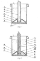
- the heater has a distributor of a fluidizing agent situated under a fluidizing bed 1 in a tank 2 with a circular cross-section, the solid phase of said fluidized bed 1 being a fine-grained ceramic material mixed with a fine-grained carbon ( Figure 1).
- the distributor body 3 has the shape of a vessel with a circular cross-section covered tightly with a lid 4, having a conical surface connected with a vertical through tube 5 for supply of compressed air as a fluidizing agent.
- the inner space of said distributor body 3 has been divided by partition walls 6 into several chambers 7, through holes 8 being provided in said lid 4 above said chambers 7.
- FIG 2 another embodiment of the invention has a distributor of fluidizing agent situated under the fluidizing bed 1 in tank 2 connected with a vertical system of two concentric through tubes, the air tube 5 and the gas tube 9 being accommodated inside it.
- the distributor body 3 is a vessel with a circular cross-section covered tightly with a lid 4 having a conical surface, the inner space of said distributor body being divided by partition walls 10 and 11 into several chambers. Some of these are used as air chambers 12 and are connected to a through air tube 5 and others, used as gas chambers 13, are connected to a gas through tube 9.
- the individual air chambers 12 have been separated by gas chambers 13 and holes 8 are provided in the lid 4 above the chambers 12 and 13.
- the diaphragm heater according to the invention is dipped in a metal bath. After the ignition of coal in the fluidized bed 1 and after obtaining a stable combustion within the whole volume of the bed an intensive combustion of the coal contained in the fluidized bed 1 takes place and said bed is set in motion by the supplied air and thus serves for heat transfer from the coal being burned through the walls of the tank 2 to the metal bath.
- Still another embodiment of the diaphragm heater according to the invention is immersed, when in operation, in the metal bath. After ignition of gas in the fluidized bed 1 and after propagation of the combustion process throughout the whole volume of the bed combustion of the gas supplied through the gas tube 9 takes place with oxygen supplied through air tube 5, the solid phase of the fluidized bed 1 being set in motion by the supplied gas.
- the air serves as a catalyst for combustion and transfers heat from the gas being burned to the walls of the tank 10.
- An advantage of the diaphragm heater or heat exchanger according to the invention as compared with the heretofore known heaters wherein the bath of melted metal (zinc) is heated through the walls of the galvanizing pot is a reduction of heat consumption per unit weight of metal plated workpieces by 10 to 20 per cent and as compared with an electric resistance heater is a reduction by half of heat consumption as referred to the theoretical standard fuel.
- the heater according to the invention enables the galvanizing efficiency to be increased by 20 to 50 per cent as compared with that obtainable in the plants heretofore used this being possible because of an increased heat load of its heating surface to as much as 233 kW per sq. m. without any danger of a negative influence of a layer of hard zinc. In consequence, the temperature of the bath can be easily maintained in conformity with technical specifications.
Landscapes
- Chemical & Material Sciences (AREA)
- Engineering & Computer Science (AREA)
- Mechanical Engineering (AREA)
- Organic Chemistry (AREA)
- Materials Engineering (AREA)
- Metallurgy (AREA)
- Chemical Kinetics & Catalysis (AREA)
- General Engineering & Computer Science (AREA)
- Combustion & Propulsion (AREA)
- Dispersion Chemistry (AREA)
- Devices And Processes Conducted In The Presence Of Fluids And Solid Particles (AREA)
- Fluidized-Bed Combustion And Resonant Combustion (AREA)
- Heat-Exchange Devices With Radiators And Conduit Assemblies (AREA)
Applications Claiming Priority (2)
| Application Number | Priority Date | Filing Date | Title |
|---|---|---|---|
| PL240563 | 1983-02-12 | ||
| PL1983240563A PL143570B1 (en) | 1983-02-12 | 1983-02-12 | Diaphragm-type heat exchanger |
Publications (1)
| Publication Number | Publication Date |
|---|---|
| EP0116920A1 true EP0116920A1 (fr) | 1984-08-29 |
Family
ID=20015891
Family Applications (1)
| Application Number | Title | Priority Date | Filing Date |
|---|---|---|---|
| EP84101385A Withdrawn EP0116920A1 (fr) | 1983-02-12 | 1984-02-10 | Appareil de chauffage à diaphragme pour réchauffer des liquides |
Country Status (3)
| Country | Link |
|---|---|
| EP (1) | EP0116920A1 (fr) |
| JP (1) | JPS59161690A (fr) |
| PL (1) | PL143570B1 (fr) |
Cited By (1)
| Publication number | Priority date | Publication date | Assignee | Title |
|---|---|---|---|---|
| EP0287644A4 (en) * | 1986-10-15 | 1991-03-20 | Kennecott Corporation | Method and apparatus to produce a hot fluidizing gas |
Citations (6)
| Publication number | Priority date | Publication date | Assignee | Title |
|---|---|---|---|---|
| US3737283A (en) * | 1971-11-26 | 1973-06-05 | Fuller Co | Fluidized solids reactor |
| DE2352412A1 (de) * | 1972-10-20 | 1974-05-02 | Sprocket Properties Ltd | Verfahren und vorrichtung zum einstellen der betriebstemperatur eines fliessbettes |
| DE2408649A1 (de) * | 1973-03-02 | 1974-09-05 | Coal Industry Patents Ltd | Verfahren und vorrichtung zur schwebebettverbrennung brennbarer stoffe |
| GB1425704A (en) * | 1972-06-16 | 1976-02-18 | British Petroleum Co | Fluidised bed combustion process |
| DE2618291A1 (de) * | 1975-05-28 | 1976-12-09 | Coal Industry Patents Ltd | Verfahren und vorrichtung zum erzeugen eines heissen gases |
| US4340000A (en) * | 1978-04-03 | 1982-07-20 | Steag Ag | Fluidized bed furnace |
Family Cites Families (1)
| Publication number | Priority date | Publication date | Assignee | Title |
|---|---|---|---|---|
| JPS5755997A (en) * | 1980-09-22 | 1982-04-03 | Hitachi Ltd | Rust-proofing lubricating grease composition |
-
1983
- 1983-02-12 PL PL1983240563A patent/PL143570B1/pl unknown
-
1984
- 1984-02-10 JP JP59024237A patent/JPS59161690A/ja active Pending
- 1984-02-10 EP EP84101385A patent/EP0116920A1/fr not_active Withdrawn
Patent Citations (6)
| Publication number | Priority date | Publication date | Assignee | Title |
|---|---|---|---|---|
| US3737283A (en) * | 1971-11-26 | 1973-06-05 | Fuller Co | Fluidized solids reactor |
| GB1425704A (en) * | 1972-06-16 | 1976-02-18 | British Petroleum Co | Fluidised bed combustion process |
| DE2352412A1 (de) * | 1972-10-20 | 1974-05-02 | Sprocket Properties Ltd | Verfahren und vorrichtung zum einstellen der betriebstemperatur eines fliessbettes |
| DE2408649A1 (de) * | 1973-03-02 | 1974-09-05 | Coal Industry Patents Ltd | Verfahren und vorrichtung zur schwebebettverbrennung brennbarer stoffe |
| DE2618291A1 (de) * | 1975-05-28 | 1976-12-09 | Coal Industry Patents Ltd | Verfahren und vorrichtung zum erzeugen eines heissen gases |
| US4340000A (en) * | 1978-04-03 | 1982-07-20 | Steag Ag | Fluidized bed furnace |
Cited By (1)
| Publication number | Priority date | Publication date | Assignee | Title |
|---|---|---|---|---|
| EP0287644A4 (en) * | 1986-10-15 | 1991-03-20 | Kennecott Corporation | Method and apparatus to produce a hot fluidizing gas |
Also Published As
| Publication number | Publication date |
|---|---|
| PL240563A1 (en) | 1984-08-13 |
| PL143570B1 (en) | 1988-02-29 |
| JPS59161690A (ja) | 1984-09-12 |
Similar Documents
| Publication | Publication Date | Title |
|---|---|---|
| US5958273A (en) | Induction heated reactor apparatus | |
| US5382412A (en) | Fluidized bed reactor heated by microwaves | |
| US5374413A (en) | Heating of fluidized bed reactor by microwaves | |
| US5308399A (en) | Method and apparatus for coating a structural component by gas diffusion | |
| US4715317A (en) | Method for producing of polycrystalline silicon and apparatus thereof | |
| CA1166825A (fr) | Generateur endothermique a double passe | |
| JPH0813111A (ja) | 溶融亜鉛めっき装置 | |
| GB2224563A (en) | Crucible furnace | |
| US3208830A (en) | Atmosphere gas generator | |
| US3079325A (en) | Device for carrying out endothermal reactions in the electric arc | |
| CS253711B2 (en) | Device for preparing phosphorous pentoxide | |
| JPS59161690A (ja) | ダイヤフラム型熱交換装置 | |
| EP0480385A1 (fr) | Installation pour le traitement chémique de pièces dans un lit fluidisé | |
| JPS58176924A (ja) | 純粋な半導体材料の製法及びその装置 | |
| NZ217238A (en) | Baking furnace for the continuous production of elongated carbon electrodes | |
| SU899454A1 (ru) | Способ получени водорода | |
| CN1006299B (zh) | 一种反射炉结构的锑白炉 | |
| SU903673A1 (ru) | Шахтна печь дл прокалки кускового материала | |
| US3749805A (en) | Fluid bed furnace | |
| GB1311100A (en) | High temperature treatment of particulate material | |
| JP2002088457A (ja) | 溶融亜鉛めっき装置 | |
| US962532A (en) | Electric furnace for metallurgical purposes. | |
| RU2063598C1 (ru) | Электропечь сопротивления | |
| SU1092165A1 (ru) | Способ газификации углеродсодержащего материала | |
| SU1224281A1 (ru) | Способ бурлени стекломассы и устройство дл его осуществлени |
Legal Events
| Date | Code | Title | Description |
|---|---|---|---|
| PUAI | Public reference made under article 153(3) epc to a published international application that has entered the european phase |
Free format text: ORIGINAL CODE: 0009012 |
|
| AK | Designated contracting states |
Designated state(s): DE FR GB IT |
|
| STAA | Information on the status of an ep patent application or granted ep patent |
Free format text: STATUS: THE APPLICATION IS DEEMED TO BE WITHDRAWN |
|
| 18D | Application deemed to be withdrawn |
Effective date: 19850502 |
|
| RIN1 | Information on inventor provided before grant (corrected) |
Inventor name: LISZKA, JERZY Inventor name: LECH, RYSZARD Inventor name: MIKULA, KAZIMIERZ Inventor name: CHLUBY, BARBARA |