EP0117103A2 - Induktionsmotoren - Google Patents
Induktionsmotoren Download PDFInfo
- Publication number
- EP0117103A2 EP0117103A2 EP84300848A EP84300848A EP0117103A2 EP 0117103 A2 EP0117103 A2 EP 0117103A2 EP 84300848 A EP84300848 A EP 84300848A EP 84300848 A EP84300848 A EP 84300848A EP 0117103 A2 EP0117103 A2 EP 0117103A2
- Authority
- EP
- European Patent Office
- Prior art keywords
- winding
- supply
- switching arrangement
- control means
- motor according
- Prior art date
- Legal status (The legal status is an assumption and is not a legal conclusion. Google has not performed a legal analysis and makes no representation as to the accuracy of the status listed.)
- Granted
Links
Images


Classifications
-
- H—ELECTRICITY
- H02—GENERATION; CONVERSION OR DISTRIBUTION OF ELECTRIC POWER
- H02P—CONTROL OR REGULATION OF ELECTRIC MOTORS, ELECTRIC GENERATORS OR DYNAMO-ELECTRIC CONVERTERS; CONTROLLING TRANSFORMERS, REACTORS OR CHOKE COILS
- H02P1/00—Arrangements for starting electric motors or dynamo-electric converters
- H02P1/16—Arrangements for starting electric motors or dynamo-electric converters for starting dynamo-electric motors or dynamo-electric converters
- H02P1/42—Arrangements for starting electric motors or dynamo-electric converters for starting dynamo-electric motors or dynamo-electric converters for starting an individual single-phase induction motor
Definitions
- This invention relates to single phase induction motors.
- a single phase induction motor comprises: a first winding arranged for energisation from a single phase supply; a second winding arranged for energisation from said supply via an electronic switching arrangement; and control means arranged to control the operation of said switching arrangement in synchronism with the supply so that the phases of the voltages across said first and second windings differ by an amount sufficient to provide a starting torque.
- the second winding comprises two portions and said switching arrangement and control means serve to connect the two portions for energisation from the supply alternately with a changeover from energisation of one portion to energisation of the other portion occurring during each half cycle of the supply voltage, the two portions being arranged to provide, when energised, magnetic fields of opposite sense.
- the switching arrangement comprises two transistors connected in a bistable circuit arrangement with each transistor having its main current path connected in series with a respective one of the two portions of the second winding across said supply via a full wave rectifying arrangement, and the control means serves to trigger the bistable circuit arrangement during each half cycle of the supply voltage.
- said second winding has one end connected to a tapping D oint on said first winding and its other end respectively connected via respective switches of said switching arrangement to the output terminals of a full wave rectifying arrangement whose input terminals are connected with said supply, and said control means is arranged to cause said switches to conduct alternately with a changeover from conduction of one switch to the other during each half cycle of the supply voltage.
- the switching arrangement comprises a bidirectional switch connected in series with said second winding across said supply, and said control means serves to close said switch during a part of each half cycle of the supply voltage.
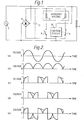
- the first motor to be described includes a conventional main first stator winding r arranged for energisation from an alternating current supply 3.
- the stator is also provided with an auxiliary second winding comprising two portions 5 and 7.
- One of the winding portions 5 is connected in series with a semiconductor switch 9 between the output terminals of a bridge full wave rectifying arrangement 11 energised from the supply 3.
- the other winding portion 7 is similarly connected across the rectifying arrangement 11 via a second semiconductor switch 13.
- the switches 9 and 13 are operated by a control circuit 15.
- the output voltage of the full wave rectifying arrangement is thus applied alternately to the winding portions 5 and 7, as illustrated in Figures 2c and 2d.
- the winding portions 5 and 7 are arranged so that the magnet fields applied to the motor rotor (not shown) by the two portions, when energised, are in opposite senses.
- the winding portions 5 and 7 thus together produce the same magnetic effect as a single winding to which is applied to a voltage of the form shown in Figure 2e.
- the voltage illustrated in Figure 2e has a fundamental component shifted by about 90° with respect to the supply voltage applied to the main motor winding 1, thus providing the quasi second phase required for self-starting of the motor.
- a smoothing capacitor 17 may be connected across the output of the rectifying arrangement 11 to reduce the harmonic components of the voltages applied to the winding portions 5 and 7, as illustrated by the dotted lines in the Figures 1 and 2.
- auxiliary winding'5, 7 suitably comprises two bifilar wound coils.
- FIG 3 shows one suitable arrangement for the switching arrangement comprising switches 9 and 13 and the control circuit 15 of Figure 1.
- the switches comprise MOS field effect transistors 19 and 21 whose gates and drains are cross-connected via resistors 23 and 25 to form a bistable circuit arrangement.
- Trigger control means for the bistable circuit is provided in the form of two capacitors 27 and 29 respectively connected between opposite sides of the supply 3 and the gates of the transistors 19 and 21.
- Each of the transistors 19 and 21 has a Zener diode 31 or 33 connected between its gate and source to prevent the transistor gates being overvolted, and a non-linear resistance 35 is connected across the supply 3 to provide voltage spike suppression.
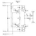
- the second motor to be described comprises a centre-tapped main first stator winding 37A, 37B arranged for energisation from an alternating current supply 39.
- the stator is also provided with a second winding 41 which is connected between the centre tap of winding 37 and the junction between two semiconductor switches 43 and 45 connected in series between the output terminals of a bridge full wave rectifying arrangement 47 whose input terminals are connected with the supply 39.
- the switches 43 and 45 are operated by a control circuit 49.
- the switches 43 and 45 operate under control of control circuit 49 so as to conduct alternately, the switch 43 becoming conducting near each peak of one set of alternate half cycles of the voltage of the supply 39, and the switch 45 becoming conducting near each peak of the other set of alternate half cycles of the supply 39.
- FIG 5 shows one suitable form for the switching arrangement comprising switches 43 and 45 and the control circuit 49 in Figure 4.
- the switches comprise MOS field effect transistors 51 and 53 each having an inverse voltage protection diode 55 or 57 connected between its source and drain.
- the transistors 51 and 53 are driven respectively by the voltages developed across two resistors 59 and 61 each connected between the source and gate of the associated transistor.
- the peak voltages developed across the resistors 59 and 61 are respectively determined by two Zener diodes 63 and 65 connected in series with a resistor 67 between the output terminals of the bridge rectifier 47, the currents in the resistors 59 and 61 being controlled by two photo-transistors 69 and 71 each having its current path connected in series with the associated resistor 59 or 61 across the associated Zener diode 63 or 65.
- the transistors 69 and 71 are, in turn, respectively controlled by the light outputs of two light emitting diodes 73 and 75, the diodes 73 and 75 each being separately connected in series with a resistor 77 and a capacitor 79 across the supply 39, but with reverse polarity so as to be lit alternately.
- the values of the capacitor 79 and resistor 77 are chosen so that the diodes 73 and 75 are lit, and hence the transistors 69 and 71 and 51 and 53 are rendered conducting alternately at the required periods relative to the waveform of the supply voltage.
- a resistor 81 and a capacitor 83 are connected in series across the winding 41.
- a Zener diode 85 connected across the output terminals of the bridge rectifier 47 provides voltage spike suppression.
- the third motor to be described comprises a first stator winding 87 arranged for energisation from an alternating current supply 89.
- the stator is also-provided with a second winding 91 connected across the supply 89 via a bidirectional semiconductor switch 93, e.g. a triac, the switch 93 being controlled by a control circuit 95 synchronised with the supply.
- a bidirectional semiconductor switch 93 e.g. a triac
- the control circuit 95 is arranged to close the switch 93 shortly before each zero crossing in the supply voltage and open the switch 93 at the following zero crossing to provide a sequence of voltage pulses of alternate polarity across the second winding 91, as illustrated in Figure 7b.
- the second winding voltage has a fundamental component phase shifted with respect to the main winding voltage by about 90°, thus providing the quasi second phase required for self-starting of the motor.
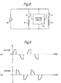
- the fourth circuit is identical to that shown in Figure 6 except that a second semiconductor switch 97 controlled by the control circuit 95 is connected in series with the first winding 87.
- control circuit 95 closes the switch 97 at each zero crossing of the supply voltage and opens the switch 97 at about each peak of the supply voltage to provide a voltage across the winding 87 of waveform as shown in Figure 9a.
- control circuit 95 closes the switch 93 at about each peak of the supply voltage and opens the switch 93 at or near each zero crossing of the supply voltage to provide a voltage across winding 91 of waveform as shown in Figure 9b.
- one of the windings may be disconnected once the motor has started. Where only one winding is switched, as in the arrangement of Figures 1, 4 and 6 the disconnected winding is conveniently the switched second winding, thereby avoiding excessive heating of the motor due to the poor waveform of the voltage applied to the second winding.
- either winding may be disconnected. The on-time of the other winding may then suitably be increased.
- control means in addition to being arranged to operate the switching arrangement to provide a starting torque, may also be arranged to obtain starting in either direction, thus providing a reversible motor.
- reversing can be obtained simply by reversing the phase of operation of the switching arrangement with respect to the supply voltage.
- reversing can be obtained by reversing the phase of both switching arrangements in the arrangement of Figure 8, or by altering the phase of the switching arrangement, e.g. by about 90°, in the arrangement of Figure 6.
Landscapes
- Engineering & Computer Science (AREA)
- Power Engineering (AREA)
- Control Of Ac Motors In General (AREA)
- Motor And Converter Starters (AREA)
Applications Claiming Priority (2)
| Application Number | Priority Date | Filing Date | Title |
|---|---|---|---|
| GB8304714 | 1983-02-21 | ||
| GB838304714A GB8304714D0 (en) | 1983-02-21 | 1983-02-21 | Induction motors |
Publications (3)
| Publication Number | Publication Date |
|---|---|
| EP0117103A2 true EP0117103A2 (de) | 1984-08-29 |
| EP0117103A3 EP0117103A3 (en) | 1985-07-31 |
| EP0117103B1 EP0117103B1 (de) | 1988-06-08 |
Family
ID=10538325
Family Applications (1)
| Application Number | Title | Priority Date | Filing Date |
|---|---|---|---|
| EP84300848A Expired EP0117103B1 (de) | 1983-02-21 | 1984-02-10 | Induktionsmotoren |
Country Status (4)
| Country | Link |
|---|---|
| US (1) | US4520303A (de) |
| EP (1) | EP0117103B1 (de) |
| DE (1) | DE3472045D1 (de) |
| GB (2) | GB8304714D0 (de) |
Cited By (3)
| Publication number | Priority date | Publication date | Assignee | Title |
|---|---|---|---|---|
| GB2162388A (en) * | 1984-07-26 | 1986-01-29 | Pt Components Inc | Motor starting circuit |
| EP0367342A1 (de) * | 1988-11-02 | 1990-05-09 | Philips Electronics North America Corporation | Steuerungseinrichtung für elektrische Mehrfachgeschwindigkeitsmotoren |
| FR2755548A1 (fr) * | 1996-11-07 | 1998-05-07 | Ksb Sa | Circuit d'alimentation d'un moteur asynchrone triphase a partir d'une source de tension monophasee |
Families Citing this family (37)
| Publication number | Priority date | Publication date | Assignee | Title |
|---|---|---|---|---|
| GB8426496D0 (en) * | 1984-10-19 | 1984-11-28 | Ass Elect Ind | Single phase induction motors |
| US5218283A (en) * | 1991-02-15 | 1993-06-08 | York International Corporation | AC motor drive system with a two phase power supply |
| US5136216A (en) * | 1991-02-15 | 1992-08-04 | York International Corporation | Ac motor drive system |
| US5146147A (en) * | 1991-02-28 | 1992-09-08 | York International Corporation | Ac motor drive system |
| GB2269244B (en) * | 1992-07-30 | 1996-05-08 | Yang Tai Her | Compound motor control circuit |
| US5483139A (en) * | 1994-03-14 | 1996-01-09 | General Electric Company | Motor start, reverse and protection system without a starting capacitor |
| US5710493A (en) * | 1995-08-25 | 1998-01-20 | Magnetic Revolutions Limited, L.L.C. | Circuit and method for alternating current motor constructions |
| AU7616096A (en) * | 1995-11-30 | 1997-06-19 | William Harry Kemp | Current modulation motor controller |
| US5742139A (en) * | 1996-07-26 | 1998-04-21 | Dana Corporation | Method and apparatus for reducing noise in a variable reluctance motor |
| US5839488A (en) * | 1997-05-29 | 1998-11-24 | Peters; Gerald L. | Hands-off low-air-loss quick-connect quick-disconnect fast-fill dunnage bag filling valve-nozzle assembly & system |
| FR2770052B1 (fr) * | 1997-10-20 | 1999-12-31 | Somfy | Moteur asynchrone monophase a deux enroulements |
| FR2772212B1 (fr) * | 1997-12-08 | 2000-02-04 | Somfy | Procede de commande de la vitesse d'un moteur asynchrone a induction monophasee |
| EP1107441A3 (de) * | 1999-12-01 | 2002-09-25 | Papst-Motoren GmbH & Co. KG | Elektronisch kommunierter Gleichstrommotor |
| DE50015828D1 (de) * | 1999-12-08 | 2010-02-04 | Ebm Papst St Georgen Gmbh & Co | Elektonisch kommutierter Gleichstrommotor |
| US6566841B2 (en) * | 2001-02-08 | 2003-05-20 | Scroll Technologies | Scroll compressor having multiple motor performance characteristics |
| US6831849B2 (en) * | 2001-04-11 | 2004-12-14 | Meritor Light Vehicle Technology, Llc | Conversion of single phase to multiple phase alternating current |
| EP1400008A1 (de) * | 2001-05-24 | 2004-03-24 | Comair Rotron, Inc. | Stator mit mehrfachwicklungskonfigurationen |
| US6989649B2 (en) * | 2003-07-09 | 2006-01-24 | A. O. Smith Corporation | Switch assembly, electric machine having the switch assembly, and method of controlling the same |
| US8540493B2 (en) | 2003-12-08 | 2013-09-24 | Sta-Rite Industries, Llc | Pump control system and method |
| BRPI0403060A (pt) * | 2004-07-23 | 2005-05-24 | Tecumseh Do Brasil Ltda | Dispositivo eletrônico de partida para compressores herméticos |
| US7686589B2 (en) | 2004-08-26 | 2010-03-30 | Pentair Water Pool And Spa, Inc. | Pumping system with power optimization |
| US7854597B2 (en) | 2004-08-26 | 2010-12-21 | Pentair Water Pool And Spa, Inc. | Pumping system with two way communication |
| US8019479B2 (en) | 2004-08-26 | 2011-09-13 | Pentair Water Pool And Spa, Inc. | Control algorithm of variable speed pumping system |
| US7845913B2 (en) | 2004-08-26 | 2010-12-07 | Pentair Water Pool And Spa, Inc. | Flow control |
| US8480373B2 (en) | 2004-08-26 | 2013-07-09 | Pentair Water Pool And Spa, Inc. | Filter loading |
| US7874808B2 (en) | 2004-08-26 | 2011-01-25 | Pentair Water Pool And Spa, Inc. | Variable speed pumping system and method |
| US8469675B2 (en) | 2004-08-26 | 2013-06-25 | Pentair Water Pool And Spa, Inc. | Priming protection |
| US8602745B2 (en) | 2004-08-26 | 2013-12-10 | Pentair Water Pool And Spa, Inc. | Anti-entrapment and anti-dead head function |
| KR20060055046A (ko) * | 2004-11-17 | 2006-05-23 | 삼성전자주식회사 | 단상유도전동기 및 그 소음 저감 방법 |
| FR2919444B1 (fr) * | 2007-07-23 | 2009-10-23 | Somfy Sas | Dispositif d'alimentation d'un actionneur domotique et procede de fonctionnement d'un tel dispositif |
| US7742670B2 (en) * | 2007-10-01 | 2010-06-22 | Corning Cable Systems Llc | Index-matching gel for nanostructure optical fibers and mechanical splice assembly and connector using same |
| EP2342402B1 (de) | 2008-10-06 | 2018-06-06 | Pentair Water Pool and Spa, Inc. | Verfahren für den betrieb eines sicherheitsvakuumablasssystems |
| US9556874B2 (en) | 2009-06-09 | 2017-01-31 | Pentair Flow Technologies, Llc | Method of controlling a pump and motor |
| CN103477075B (zh) | 2010-12-08 | 2016-12-21 | 滨特尔水池水疗公司 | 用于安全真空释放系统的排放真空释放阀 |
| TWI458253B (zh) * | 2011-05-10 | 2014-10-21 | Delta Electronics Inc | 交流驅動馬達 |
| ES2640280T3 (es) | 2011-11-01 | 2017-11-02 | Pentair Water Pool And Spa, Inc. | Sistema y método de bloqueo de flujo |
| US9885360B2 (en) | 2012-10-25 | 2018-02-06 | Pentair Flow Technologies, Llc | Battery backup sump pump systems and methods |
Family Cites Families (8)
| Publication number | Priority date | Publication date | Assignee | Title |
|---|---|---|---|---|
| US3519911A (en) * | 1966-07-05 | 1970-07-07 | Harry J Frank | Alternating current motor starting control |
| US3761792A (en) * | 1972-02-07 | 1973-09-25 | Franklin Electric Co Inc | Switching circuit for motor start winding |
| GB1464454A (en) * | 1973-09-20 | 1977-02-16 | Unisearch Ltd | Type of single phase squirrel cage induction motor assembly |
| US4060754A (en) * | 1976-05-14 | 1977-11-29 | Massachusetts Institute Of Technology | Electronic motor that includes an electronic waveform synthesizer and the synthesizer per se |
| US4307327A (en) * | 1979-09-17 | 1981-12-22 | Franklin Electric Co., Inc. | Control arrangement for single phase AC systems |
| GB2067370B (en) * | 1979-12-28 | 1984-01-25 | Myson Group Ltd | Electric motor start up control |
| DE3069643D1 (en) * | 1980-11-28 | 1984-12-20 | Ibm | Motor control system for a single phase induction motor |
| CA1177877A (en) * | 1981-01-30 | 1984-11-13 | Herman P. Schutten | Control apparatus for single phase ac induction motor |
-
1983
- 1983-02-21 GB GB838304714A patent/GB8304714D0/en active Pending
-
1984
- 1984-02-10 DE DE8484300848T patent/DE3472045D1/de not_active Expired
- 1984-02-10 EP EP84300848A patent/EP0117103B1/de not_active Expired
- 1984-02-10 GB GB08403550A patent/GB2135539B/en not_active Expired
- 1984-02-15 US US06/580,558 patent/US4520303A/en not_active Expired - Fee Related
Cited By (4)
| Publication number | Priority date | Publication date | Assignee | Title |
|---|---|---|---|---|
| GB2162388A (en) * | 1984-07-26 | 1986-01-29 | Pt Components Inc | Motor starting circuit |
| EP0367342A1 (de) * | 1988-11-02 | 1990-05-09 | Philips Electronics North America Corporation | Steuerungseinrichtung für elektrische Mehrfachgeschwindigkeitsmotoren |
| FR2755548A1 (fr) * | 1996-11-07 | 1998-05-07 | Ksb Sa | Circuit d'alimentation d'un moteur asynchrone triphase a partir d'une source de tension monophasee |
| EP0841745A1 (de) * | 1996-11-07 | 1998-05-13 | Ksb S.A. | Auf eine Einphasenspannungsversorgung basierende Drehstromversorgungsschaltung für einen Drehstromasynchronmotor |
Also Published As
| Publication number | Publication date |
|---|---|
| GB8403550D0 (en) | 1984-03-14 |
| DE3472045D1 (en) | 1988-07-14 |
| GB2135539A (en) | 1984-08-30 |
| GB2135539B (en) | 1986-09-10 |
| GB8304714D0 (en) | 1983-03-23 |
| EP0117103B1 (de) | 1988-06-08 |
| US4520303A (en) | 1985-05-28 |
| EP0117103A3 (en) | 1985-07-31 |
Similar Documents
| Publication | Publication Date | Title |
|---|---|---|
| US4520303A (en) | Induction motors | |
| KR830001998B1 (ko) | 제어 자속밀도를 갖는 가변 속도 전기기계장치 | |
| US6087799A (en) | Switching circuit for a reluctance machine | |
| US5764019A (en) | Control circuit and system for a switched reluctance machine and method of operating | |
| US6005321A (en) | Variable reluctance motor systems | |
| US4667282A (en) | Multiphase rectifier circuit with dynamic AC input to DC output voltage range compression utilizing half and full wave rectification modes | |
| US4723202A (en) | Converter-fed AC machine without damper winding | |
| Julian et al. | Multi-speed control of single-phase induction motors for blower applications | |
| US4188659A (en) | Static AC/AC thyristor converter for a self-driven synchronous motor | |
| JPH0461597B2 (de) | ||
| US3467904A (en) | Speed control system utilizing constant-amplitude voltage of variable frequency to energize an electric motor | |
| US5990655A (en) | Method of operating an inverter for powering an induction motor | |
| US4270076A (en) | Circuit for a brushless D.C. motor | |
| RU2037258C1 (ru) | Утроитель частоты с трехфазным входом | |
| RU2030090C1 (ru) | Электропривод | |
| RU2017309C1 (ru) | Удвоитель частоты с фазным входом | |
| JPS6373897A (ja) | 電動機の可変速運転装置 | |
| US5973472A (en) | Single-phase asynchronous motor with two windings | |
| US3497783A (en) | Brushless direct current motor | |
| RU2006159C1 (ru) | Умножитель частоты трехфазной сети | |
| RU1775808C (ru) | Вентильный электропривод посто нного тока | |
| RU2027291C1 (ru) | Умножитель частоты трехфазной сети | |
| RU2024174C1 (ru) | Трехфазный удвоитель частоты | |
| SU1029347A2 (ru) | Вентильный электродвигатель | |
| JPS61214794A (ja) | 可変速電動機 |
Legal Events
| Date | Code | Title | Description |
|---|---|---|---|
| PUAI | Public reference made under article 153(3) epc to a published international application that has entered the european phase |
Free format text: ORIGINAL CODE: 0009012 |
|
| AK | Designated contracting states |
Designated state(s): DE FR |
|
| PUAL | Search report despatched |
Free format text: ORIGINAL CODE: 0009013 |
|
| AK | Designated contracting states |
Designated state(s): DE FR |
|
| 17P | Request for examination filed |
Effective date: 19860120 |
|
| 17Q | First examination report despatched |
Effective date: 19861114 |
|
| GRAA | (expected) grant |
Free format text: ORIGINAL CODE: 0009210 |
|
| AK | Designated contracting states |
Kind code of ref document: B1 Designated state(s): DE FR |
|
| REF | Corresponds to: |
Ref document number: 3472045 Country of ref document: DE Date of ref document: 19880714 |
|
| ET | Fr: translation filed | ||
| PLBE | No opposition filed within time limit |
Free format text: ORIGINAL CODE: 0009261 |
|
| STAA | Information on the status of an ep patent application or granted ep patent |
Free format text: STATUS: NO OPPOSITION FILED WITHIN TIME LIMIT |
|
| 26N | No opposition filed | ||
| PGFP | Annual fee paid to national office [announced via postgrant information from national office to epo] |
Ref country code: FR Payment date: 19900202 Year of fee payment: 7 |
|
| PGFP | Annual fee paid to national office [announced via postgrant information from national office to epo] |
Ref country code: DE Payment date: 19900424 Year of fee payment: 7 |
|
| PG25 | Lapsed in a contracting state [announced via postgrant information from national office to epo] |
Ref country code: FR Effective date: 19911031 |
|
| PG25 | Lapsed in a contracting state [announced via postgrant information from national office to epo] |
Ref country code: DE Effective date: 19911101 |
|
| REG | Reference to a national code |
Ref country code: FR Ref legal event code: ST |