EP0117119A2 - Verstärktes Bauelement und Verfahren zu dessen Herstellung - Google Patents
Verstärktes Bauelement und Verfahren zu dessen Herstellung Download PDFInfo
- Publication number
- EP0117119A2 EP0117119A2 EP84300946A EP84300946A EP0117119A2 EP 0117119 A2 EP0117119 A2 EP 0117119A2 EP 84300946 A EP84300946 A EP 84300946A EP 84300946 A EP84300946 A EP 84300946A EP 0117119 A2 EP0117119 A2 EP 0117119A2
- Authority
- EP
- European Patent Office
- Prior art keywords
- bond
- layer means
- metal layer
- layers
- metal
- Prior art date
- Legal status (The legal status is an assumption and is not a legal conclusion. Google has not performed a legal analysis and makes no representation as to the accuracy of the status listed.)
- Granted
Links
Images



Classifications
-
- B—PERFORMING OPERATIONS; TRANSPORTING
- B21—MECHANICAL METAL-WORKING WITHOUT ESSENTIALLY REMOVING MATERIAL; PUNCHING METAL
- B21D—WORKING OR PROCESSING OF SHEET METAL OR METAL TUBES, RODS OR PROFILES WITHOUT ESSENTIALLY REMOVING MATERIAL; PUNCHING METAL
- B21D49/00—Sheathing or stiffening objects
-
- B—PERFORMING OPERATIONS; TRANSPORTING
- B21—MECHANICAL METAL-WORKING WITHOUT ESSENTIALLY REMOVING MATERIAL; PUNCHING METAL
- B21D—WORKING OR PROCESSING OF SHEET METAL OR METAL TUBES, RODS OR PROFILES WITHOUT ESSENTIALLY REMOVING MATERIAL; PUNCHING METAL
- B21D53/00—Making other particular articles
- B21D53/92—Making other particular articles other parts for aircraft
Definitions
- the field of this invention is that of inflated composite metal members and the invention relates more particularly to structural members made from inflated composite metals and to methods for making such structural members suitable for use in high performance aircraft and the like.
- the resulting titanium structural members have accurately-formed stiffened portions to provide the members with desired, high strength-to-weight ratios; that the members are free of anomalous stress areas and areas of weakness at the diffusion bond locations; and that the members are adapted to be made and used with greater versatility than was possible with the previously used riveted structural assemblies. It would be desirable to provide similar structural members formed of high strength aluminum alloys and the like for use in high performance aircraft but the slow and involved processes used in making the improved titanium structural members are not suited for use with high strength aluminum alloys which are characterized by surface oxides impervious to the noted diffusion bonding techniques.
- the novel and improved structural members of this invention comprise layers of high strength, precipitation-hardened aluminum alloys or the like which have solid phase metallurgical bonds hermetically sealing portions of the metal layers together around precisely defined interfacial areas between the layers which are free of such bonds.
- the bonds are formed and portions of the metal layers are selectively deformed at the bond-free areas to form precisely stiffened portions of the structural members so that the products are substantially free of anomalous stresses and localized areas of weakness.
- a layer of another aluminum material or the like is disposed between the precipitation-hardened metal layers forming a member, to cushion applied stresses and to assure that the desired bond strength, bond reliability, and bond hermeticity is achieved between the layers. After forming, the member is treated for precipitation-hardening the member alloys.
- the novel and improved structural member results from use of the novel and improved process of this invention which comprises the steps of disposing a pattern of bond-preventing material on one surface of a layer of precipitation-hardenable aluminum alloy or the like, disposing a corresponding second metal layer preferably but not necessarily of the same alloy and thickness in interfacing relation to the first layer to cover the pattern, and passing the metal layers between a pair of pressure bonding rolls to elongate and reduce the thickness of the metal layers to a precisely predetermined extent sufficient to form at least incipient solid phase metallurgical bonds between the layers while also elongating the pattern of bond-preventing material in an accurately predetermined manner to precisely define selected bond-free areas between the layers.
- the bond-preventing materials are adapted to decompose and form a gas when heated to a selected temperature
- the alloys used in the member layers preferably have grain refining means or the like adapting the layer materials to be substantially deformed to elongations of 60% or more or even superplastically deformed when heated to said selected temperature.
- the alloys are selected so that thermomechanical processing can be used to produce selected equiaxial on nonequiaxial grain structures, thus providing for selected axes of material deformation.
- the interfacing surfaces of the metal layers are mechanically cleaned for removing oxides from the surfaces and the metal layers are heated to a limited degree for a limited period of time to free the layer surfaces from moisture without excessively reforming oxides on the layer surfaces just prior to passing the layers between the pressure bonding rolls.
- at least one layer of another aluminum material or the like is disposed between the precipitation-hardenable metal layers as the layers are interfacially arranged. In that way, forming of the noted solid phase metallurgical bonds is facilitated and enhanced and further improved bond quality is achieved.
- the metal layers are also heated to improve the solid phase metallurgical bonds between the metal layers for hermetically sealing the layers together around the bond-free areas between the layers and for reducing anomalous stresses and localized areas of weakness in the noted bonds, the layers preferably being heated to a temperature below said selected temperature for improving the bonds without substantially decomposing the bond-preventing materials.
- the bonded metal layers are preferably restrained between profile molds or forming dies or the like so that the pattern of bond-preventing material between the layers is precisely aligned with selected profile mold configurations provided by the molds.
- the metal layers are heated to said selected deformation temperature and a selected gas or other fluid pressure is established in the bond-free areas between the layers for deforming selected portions of the metal layers superplastically or the like into the profile mold configurations for providing accurately-formed stiffening portions of the desired structural member. This heating also serves to further improve the bonds between the metal layers and to substantially eliminate anomalous stress and localized areas of weakness in the bonds.
- the metal layers are heated to said selected temperature at a selected rate so that the bond-preventing materials are thermally decomposed to form a gas for establishing said selected fluid pressure and for plastically deforming the metal layers at a selected rate to thin out the layer material while avoiding localized necking down of the layer materials within the deformed portions of the metal layers.
- the stiffened portions of the members are provided with predetermined strength.
- the metal layer materials are then treated in conventional manner for precipitation-hardening the metal layer materials to improve that strength. In that way, it is found that the structural members are accurately-formed to have improved strength-to-weight ratios, are substantially free of anomalous stresses and localized bond weaknesses, and provide the necessary high strength and performance reliability to be used in manufacture of high performance aircraft and the like.
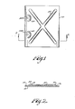
- Figs. 1 and 2 indicates the novel and improved structural member of this invention which is shown to include layer means 12, 14 of high strength, precipitation-hardened aluminum alloys or the like which have solid phase metallurgical bonds (indicated at 16 in Fig. 2) hermetically sealing portions of the metal layer means together around precisely defined areas (indicated at 18 in Fig. 2) which are free of such bonds.
- the bond areas 16 are substantially free of anomalous stresses and areas of localized weakness, and selected portions 20 of the metal layer means are deformed over the bond-free areas to provide selectively stiffened portions of the member which are precisely formed and configured so that the structural member has precisely predetermined strength and stiffness characteristics and the like, whereby the member is adapted for use in high performance aircraft and the like to achieve intended strength-to-weight properties and to meet designed structural strength and stiffness specifications.
- the stiffened portions 20 are arranged to provide selected stiffness across the member while also providing intended strength at areas 20a where the member is to be secured to another member or the like as will be understood.
- the structural strength member 10 is provided with any other corresponding pattern of stiffened portions within the scope of this invention.
- the novel and improved structural member 10 is formed using the novel and improved method of this invention so that the structural member has the desired characteristics as noted above. That is, a layer 12 of a precipitation-hardenable metal alloy is advanced by being fed from a coil 22 or the like and a second metal layer 14, also preferably comprising a precipitation-hardenable metal alloy, is advanced as from a second coil 24, or the like so that surfaces 12.1, 14.1 of the layers are moved into interfacing relation to each other and so that the layers are passed between a pair of pressure bonding rolls 26 as is indicated by the arrows 22a, 24a in Fig. 3.
- the metal layers 12 and 14 are typically but not necessarily of substantially equal thickness and each comprises a precipitation-hardenable aluminum alloy preferably having grain refining means or the like in the alloy adapting the alloy to be plastically deformed to a substantial extent or even to be superplastically deformed when the aluminum alloy is heated to a selected deformation temperature.
- a precipitation-hardenable aluminum alloy preferably having grain refining means or the like in the alloy adapting the alloy to be plastically deformed to a substantial extent or even to be superplastically deformed when the aluminum alloy is heated to a selected deformation temperature.
- other precipitation-hardenable alloys are also used in the layers 12 and 14 within the scope of this invention.
- the metal layers 12 and 14 are formed of precipitation-hardenable aluminum alloys having nominal compositions by weight as set forth in Table I below:
- the copper, zinc and zirconium constituents for example are believed to serve as grain refining means for enhancing deformability of the alloys so that, when the alloys have been subjected to thermal-mechanical processing and the like in known manner, the alloys are believed to be capable of elongating plastically or superplastically up to the levels set forth in Table I when heated to deformation temperatures as specified in Table I at selected rates.
- the alloys are deformable to the indicated extents at low but practical and controllable strain rates without fracture and, even when not subjected to full thermal-mechanical preparation for achieving superplasticity or when deformed at somewhat greater strain rates, are still capable of being substantially deformed to elongations of 60% or better suitable for forming aircraft structural members and the like without experiencing anomalous or unpredictable necking down of the alloy materials to any significant extent in the deformed areas.
- the metal alloys are adapted to be formed into stiffening shapes by controlled gas or other fluid-pressure inflation with assurance that the resulting stiffened member has predicted and reproducible strength properties.
- the surfaces 12.1 and 14.1 of the metal layers are cleaned for removing bond-deterring greases and the like from the layer surfaces before the metal layers are brought into interfacial relation to each other.
- the layer surfaces are mechanically cleaned by wire brush means or the like as is diagrammatically illustrated at 28 in Fig. 3 for mechanically removing oxides from the layer surfaces and, where the metal layers 12 and 14 embody aluminum alloy materials as is preferred, the layer surfaces are preferably heated by infrared lamp means or the like as is diagrammatically indicated at 30 in Fig. 3 for freeing the mechanically cleaned surfaces of the layers from moisture just before the layer sufaces are brought into interfacial relation to each other between the pressure bonding rolls 26.
- the layer surfaces are heated to a selected limited temperature for a selected period of time for removing such moisture from the .layer surfaces while also avoiding excessive reformation of oxides on the layer surfaces.
- the layer surfaces 12.1, 14.1 are preferably heated to a surface temperature from about 100°C. to about 150 °C. for a period from about 1 to 20 minutes just prior to being advanced between the bonding rolls, a particularly preferred heating being for about 2 minutes at 150° C. In that way the metal layers are better adapted to be metallurgically bonded together as is described below.
- one or more patterns 32 of a bond-preventing or stop weld material are disposed on at least one of the metal layer surfaces 12.1 and the other metal layer 14 is then brought into interfacing relation to the layer 12 to cover the pattern.
- the bond-preventing pattern is precisely located on the layer 12 by use of a mask or the like or by transfer from a paper tape or the like or in any other conventional manner within the scope of this invention.
- a strip of transfer paper 34 or the like is advanced from a reel 36 to a take-up reel 38 and is guided to pass over the metal layer surface 12.1 by guide rolls 40 so that the bond preventing patterns 32 are transferred from the paper to the layer surface 12.1 as the patterns are pressed against the layer surface by the transfer roll 42 as will be understood.
- bond-preventing patterns of any selected configuration are accurately positioned on the metal layer 12.
- the bond-preventing patterns are formed on the strip surface by silk screening although any other conventional process for forming the pattern is used within the scope of this invention.
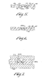
- the metal layers 12 and 14 are then bonded together to form a composite metal sheet 44 while leaving areas between the layers defined by the bond-preventing material free of bonds as is illustrated at 32a in Figs. 4-5.
- the metal layers 12 and 14 are preferably pressed together between the pressure bonding rolls 26 for elongating and reducing the thicknesses of the metal layers to an extent sufficient to form at least incipient solid phase metallurgical bonds 46 (see Fig. 5) between selected portions of the metal layers and for elongating the pattern 32 of bond-preventing material to define selected interfacial areas 32a (see Figs. 4 and 5) between the layers which are free of such bonds.
- the layer materials are rolled down using the squeezing rolls 26 to form composite metal sheet 44 incorporating the metal layers 12 and 14 which have been elongated in the direction of rolling and bonded together and incorporating the bond-preventing pattern 32 which has also been elongated in the same direction as indicated at 32a and which is now embedded between the layers 12 and 14 in the composite sheet 44.
- the reduction in thickness of the metal layers 12 and 14 is made under conditions as taught in US Patent No. 2,691,815 for example to bring about formation of solid phase, green, metallurgical bonds between the layers and the bond-preventing pattern 32 provided on layer 12 is originally dimensioned to allow for controlled elongation of a pattern by the pressure rolls 26 under those solid phase bonding conditions.
- the metal layers as specified in Table I are pressed together at or near room temperature (up to about 100°C.) and the layers are rolled with the rolls 26 preferably heated to about 100° C. for reducing the layer thicknesses on the order of about 50 to 80% in forming initial solid phase bonds 46 between layers of aluminum alloy materials. See Fig. 5. In that way, the solid phase bonding occurs between the layers 12 and 14 throughout areas of interfacial contact between the layers except at the location defined by elongated bond-preventing pattern 32a.
- the layer materials are adapted to be symmetrically elongated for elongating the bond-preventing pattern 32 in a precisely predetermined way so that the bond-free interfacial area 32a between the bonded metal layers has a precisely defined configuration.
- the bond-preventing material forming the pattern 32 is selected to withstand the rolling deformation as above described without substantially decomposing or separating under the pressure and temperature-conditions encountered during the rolling.
- the bond-preventing material is selected so that it disassociates or decomposes when heated or otherwise raised above a selected, relatively higher temperature for generating a gas.
- the bond-preventing material is adapted to decompose and generate a gas when the material is heated to a temperature corresponding to a suitable or preferred plastic deformation temperature of the materials embodied in the metal layers 12 and 14.
- the bond-preventing material is used in the patterns 32 are selected from the group having compositions as set forth in Table II:
- the composite metal sheet 44 is heated to a selected temperature by heating means as diagrammatically illustrated at 45 in Fig. 3 for sintering or improving the initial solid phase bonds 46 so that the bonds hermetically seal the metal layers 12 and 14 together around the bond-free interfacial areas as is diagrammatically illustrated at 46a in Fig. 5.
- the bond-preventing patterns 32a are formed of heat-decomposable materials as described above, the metal layers are sintered at a temperature relatively lower than the decomposition temperature of the bond-preventing materials for improving the bonds 46 without substantially decomposing the bond-preventing material.
- the composite metal sheet 44 is heated to a temperature in the range from about 150°C. to about 400°C. for a period from about 1 to 8 hours to complete the bonds 46a and to hermetically seal the metal layers 12 and 14 together completely around the bond-free areas 32a.
- the hermetic bonds between the metal layers prevent undesired migration of the bond-preventing materials into the areas which are intended to be fully bonded and prevent gases resulting from decomposition of the bond-preventing materials from working between the layers 12 and 14 to cause bond deterioration as will be understood.
- the hermetic seal of the bonds also prevents oxide reformation at the bonded aluminum layer surfaces in the bonded areas which could also result in bond deterioration. This is particularly advantageous where the layer material has a significant magnesium constituent tending to result in acicular magnesium oxide formations. In that way, it is assured that the bond-preventing pattern 32a precisely defines the edges of the bond-free areas between the layers for purposes to be described below. Such a hermetic seal is also desirable during use of the member 10 as will be understood.
- the heating of the composite shape 44 for improving the bonds 46 also serves to substantially reduce or even to substantially eliminate anomalous stresses and localized areas of weakness from the bonds 46 illustrated at 47 and 49 in Fig. 5 as is diagrammatically indicated by line 46a in Fig. 6.
- the bond growth relieves stresses 47 which may have been formed in the bond areas during rolling reduction of the thickness of the layers 12 and 14 and reduces bond artifacts 49 so that the bond interface can even be effectively eliminated between the metal layers, the strength of the bond across the interface then substantially corresponding to the strength of the metal layer materials themselves.
- the above-described thermal-mechanical process for forming and improving the solid phase metallurgical bonds 6 also serves to enhance the plastic deformability of the alloy materials. That is, where the aluminum alloy materials as specified in Table I are reduced in thickness on the order of 50 to 80% in forming the solid phase bonds 46 and where the bonded layers are then heated to temperatures in the ranqe from 250°C. to 400°C. for periods from 1 to 8 hours for improving the bonds, it is believed that such treatment enhances the formability of the noted aluminum alloys so that they display greater elongation when subsequently deformed as is described below.
- the composite metal sheet 44 is preferably cut into sections 44a as indicated by broken lines 48 in Fig. 3 so that each of the separate sections 44a includes at least one of the elongated bond-preventing patterns 32a as shown in Fig. 4 and is adapted for forming an individual structural member 10.
- the separated sheet section 44a is then further formed by blanking or bending or the like as may be desired and is preferably placed and restrained between profile mold sections 50, 52 or the like as is illustrated in Fig. 7 so that individual profile mold configurations 50a are aligned with corresponding portions of the bond-preventing pattern as is indicated at 32a.1 in Fig. 7.
- the bond-free area 32a is precisely defined and is easily aligned with the profile mold configurations as will be understood.
- the composite metal sheet section 44a is then heated to a selected deformation temperature of the layer material as above described and an elevated fluid pressure is established in the bond-free areas 32a between the layers for deforming or inflating at least one of the layers 12 or 14 into a corresponding profile mold configuration 50a to form precisely defined and shaped stiffened portions 20 of the structural member 10 as is indicated by broken lines 20 in Fig. 8.
- the elevated fluid pressure is adapted to be established between the metal layers by inserting a needle-like nozzle between the layers 12 and 14 or through one of the layers into the bond-free areas 32a and by introducing an hydraulic pressure in known manner within the scope of this invention.
- the composite metal sheet section 44a is preferably heated to a metal layer deformation temperature at which decomposition of the bond-preventing material also occurs, thereby to establish the desired elevated gas pressure in situ between the metal layers for deforming or inflating parts of the layers to form the stiffened portions 20 of the member.
- Such heating for deterioration or inflation of the member layers typically serves to further improve the bond between the metal layers.
- the rate of heating of the sheet sections 44a is preferably regulated to be very slow to assure that the desired degree of elevated fluid pressure is achieved in the bond-free areas 32a to provide very low strain rates for achieving the desired deformation of the layer materials by super-plastic deformation or the like without causing any significant necking down of the layer materials in forming the stiffening sections 20 of the member 10.
- a more rapid heating rate may be used.
- the structural member 10 of this invention formed as above described is then subjected to conventional precipitation hardening procedures for hardening the metal alloys of the layers 12 and 14 in the member, thereby to achieve desired high strength in the member materials as will be understood.
- that treatment involves heating the member to solutionizing and aging temperatures in conventional sequence.
- the member 10 is heated to a solutionizing temperature in the range from 480° C to 530° C . for about 15 minutes to one hour and is then quenched in water at a temperature not over about 30°C. within about 5 seconds of removal from the heating furnace.
- Such heating typically provides further improvement in the strength of the bonds between the member layers.
- the member materials are then aged by heating the water to temperatures in the range for about 120°C. to 190 P C. for about 3 to 24 hours. Alternately, the materials are aged for longer periods at room temperature or the like in any conventional manner. As procedures for hardening the noted alloys are well known, they are not further described and it will be understood that the hardening steps are conventional.
- the metal layer means 12 and/or 14 also comprise an additional layer 54 of another aluminum alloy or the like, the additional layer material being selected to facilitate forming and maintaining of solid phase metallurgical bonds between the precipitation-hardenable alloys of the layers 12 and 14.
- the additional layer material 54 is preferably bonded to the precipitation-hardened layers 12 and/or 14 by any conventional hot or cold roll bonding or the like so that the bond interfaces 56 between the layers 54 and the layers of the precipitation-hardenable alloys 12 and 14 are substantially free of stress anomalies or localized areas of weakness.
- the metal layers 12 and 14 are then cleaned and advanced as shown in Fig.
- the additional metal layer means 54 are brought into interfacing relation to each other at the bonding rolls 26 to be located between the precipitation-hardenable portions of the layers 12 and 14 as the metal layers are squeezed together so that the above-described solid phase metallurgical bonds are formed between the metal layers 54 as illustrated in Fig. 10.
- the initially bonded member is then adapted to be sintered, inflated and hardened as described above and it is found that the characteristics of the resulting member are even further improved over structural member prepared by the previously described methods.
- the additional layer materials have thicknesses of at least about 0.010 inches to permit roll bonding without separation but are otherwise preferably limited to about 10% of the thickness of the layers 12 and/or 14 so that the member 10a is primarily composed of the higher strength precipitation-hardenable alloys of layers 12 and 14.
- the additional aluminum materials are selected from the materials set forth in Table III as follows:
- Structural members produced in that alternate method result in structural members having further improved characteristics as is diagrammatically illustrated in Fig. 13. That is, where the strip materials are bonded together without the regulated moisture-removing step and without the interliner layers as described, the strength of the bonds between the layers tends to improve when the layer materials are sintered, heated for inflation, and solutionized as indicated by curve 57a in Fig. 13. Then the peel strength of the bonded layers decreases as the layer materials are more fully hardened. Better bonds are obtained between the layers as is indicated by curve 57b in Fig. 13 when the regulated moisture-removing preheating step is used in the bonding process as previously described. Again, there is a reduction of bond peel strength as the layer materials are hardened as is diagrammatically illustrated by curve 57b.
- a separate additional layer of material 58 is advanced from a separate pay-out reel 60 to be fed between precipitation-hardenable alloy layers 12 and 14 as shown in Fig. 11 as those hardenable alloy layers are advanced between the pressure bonding rolls 26.
- the additional metal layer material is also subjected to cleaning and drying as in the case of the metal layers 12 and 14 previously described and the bond-preventing pattern 32 is formed on either of the interfacing layer surfaces of the layers 12, 14 or 58 as shown in Fig. ll.
- the material of layer 56 is also selected to facilitate forming of the solid phase metallurgical bonds as described above and in preferred embodiments of the invention comprises a material selected from Table III. That is, as is shown in Fig. 12, the solid phase metallurgical bonds 62 in the member 10b are formed between opposite sides of the metal layer 58 and the respective precipitation-hardenable alloy layers 12 and 14. Again the thickness of the metal layer 58 is preferably at least 0.010 inches and comprises less than about 10% of the thickness of the metal layers 12 and 14 for reasons noted above. The alternate process also achieves bond advantages as indicated by curve 57c in Fig. 13.
- Two strips of 1145 Alloy Aluminum each about 0.063 inches thick were scrubbed and wire-brushed for physically removing oxides from surfaces of the strips for forming substantially virgin metal surfaces on the strips.
- the strip surfaces were promptly heated to a temperature of about 100°C. for 15 minutes for removing moisture from the strip surfaces without excessively reforming oxides on the strip surfaces.
- the strips were then immediately arranged in interfacing relation and were passed between pressure bonding rolls heated to 100°C. where the strips were squeezed together with about 60% reduction in thickness for roll-bonding strip surfaces together to form a composite metal member having solid phase metallurgical bonds between the metal layers.
- the composite member was then heated to a temperature of 260°C. for 45 minutes in air for improving the bond between the metal strips.
- a comparison member was prepared in the same manner except that, after wire brushing, the strip surfaces were held at room temperature (20°C.) for 15 minutes before being roll-bonded together. Using conventional peel strength test procedures, it was found that the strips heated to 100°C. for 15 minutes before bonding as described had bond strengths 2 to 3 times stronger than the bonds in the comparison member.
- Two strips of precipitation-hardenable 7075 Alloy Aluminum in T-0 temper condition and each about 0.063 inches thick were scrubbed and wire-brushed for mechanically removing oxides from strip surfaces.
- a pattern of the epoxy- based bond-preventing material identified at C in Table II was disposed at a selected location on the brushed surface of one of the strips by silk screening and was cured by being heated to 200° C. for 3 minutes. The brushed surfaces were then promptly brought into interfacing relation with the bond-preventing pattern there between and were passed between pressure bonding rolls heated to a temperature of about 100° C. for roll-bonding or pressure-welding the strips together.
- the strips were elongated and reduced in thickness by 60% to form a composite metal member having solid phase metallurgical bonds between the strips except in a bond-free area between the strips which was precisely defined by the pattern of bond-preventing material as elongated during the roll bonding of the strips.
- the composite member was heated to a temperature of 260° C. for about one hour to improve the metallurgical bonds between the strips in the solid phase and for reducing anomalous stress areas in the bonded strip materials. At that point, the materials were. found to have sufficient bond strength between the metal layers to permit convenient handling.
- the composite member was then restrained between profile molds having mold configurations aligned with the bond-preventing pattern between the metal layers and was heated to a temperature of 427° C.
- those portions of the composite member are adapted to be inflated or deformed after heating to the noted temperature by introducing an elevated fluid pressure into the bond-free area between the strips through an inflating nozzle forced between the strips as will be understood.
- the precipitation-hardenable member materials were then hardened in conventional manner.
- the member was found to be stiff,suitable for use as a structural panel member or the like.
- the deformed portions of the member were found to be free of significantly necked-down portions so that the material in the deformed portions of the member layers were thinned to a relatively uniform extent.
- Two strips of precipitation-hardenable 7075-T-0 Alloy Aluminum were scrubbed and were wire-brushed for physically removing oxides from surfaces of the strips.
- a pattern of bond-preventing material was placed on a wire-brushed surface of one of the strips and cured as described with reference to Example 4. Surfaces of the strips were heated to a temperature of about 150° C. for about 15 minutes for removing moisture from the strips without tending to reform excessive thicknesses of oxides on the brushed strip surfaces.
- the strips were then roll-bonded together and subjected to heating, and inflating steps as described in Example 4.
- the member was then heated to a temperature of 480° C. for 15 minutes, was immediately quenched in water at less than 30° C., and was heated to a temperature of 120° C.
- Each strip comprised a layer of precipitation-hardenable 7075 Alloy Aluminum having a layer of 7072 Alloy Aluminum roll-bonded on each outer surface of the 7075 Alloy layer in known manner so that the bond interfaces between the layers of the strip were free of anomalous areas of stress or bond weakness.
- the 7075 Alloy material was adapted by reason of its composition and previous thermomechanical processing to be plastically deformed to a substantial extent (80% elongation or more) and each of the strips was 0.063 inches thick, the 7072 Alloy layers each comprising about 2.5 to 5.0% of the total thickness of the strip.
- the strip materials were scrubbed and the 7072 Alloy surfaces of the strips were wire brushed for physically removing oxides therefrom.
- a pattern of bond-preventing material as described at C in Table II was placed on one of the brushed strip surfaces and cured as described in Example 4 and surfaces of the strips were heated to 150° C. for about 2 minutes for removing moisture from the strip surfaces without tending to reform excessive oxide layers on the brushed strip surfaces.
- the strips were then roll-bonded together between pressure bonding rolls heated to 100° C. to be reduced in thickness by 60% for forming a composite metal member having solid phase metallurgical bonds between the strips except in bond-free areas precisely defined between the strips by the now elongated pattern of bond-preventing material.
- the composite member was heated to a temperature of 260° C.
- the composite member as then restrained between profile molds so that profile configurations provided by the molds were aligned with the bond-free areas between the strips.
- the composite member was then heated to a temperature of 430° C. for 0.5 hours for thermally-decomposing the bond-preventing material to form a gas and for heating the strip materials to a desired plastic deformation temperature so that the strip materials were deformed into the profile mold configurations by the gas to form desired stiffening portions of the composite member.
- the composite member was then heated to a solutionizing temperature of 480° C. for 15 minutes, was promptly quenched in water at 30° C. or less, and was heated to an aging temperature of 120° C. for 24 hours for precipitation-hardening the strip materials.
- the member as formed was found to be strong and stiff and the deformed portions of the member were substantially uniformly thin and were found to be free of significantly necked-down portions. No anomalous stress areas or areas of significant bond weakness were observed in the member and the member was precisely formed with intended dimensions and structural characteristics suitable for permitting use of the member in aircraft structural strength applications. Very high strength bonds were found to exist between the member layers.
Landscapes
- Engineering & Computer Science (AREA)
- Mechanical Engineering (AREA)
- Aviation & Aerospace Engineering (AREA)
- Pressure Welding/Diffusion-Bonding (AREA)
- Laminated Bodies (AREA)
- Heat Treatment Of Nonferrous Metals Or Alloys (AREA)
Applications Claiming Priority (2)
| Application Number | Priority Date | Filing Date | Title |
|---|---|---|---|
| US46619383A | 1983-02-14 | 1983-02-14 | |
| US466193 | 1983-02-14 |
Publications (3)
| Publication Number | Publication Date |
|---|---|
| EP0117119A2 true EP0117119A2 (de) | 1984-08-29 |
| EP0117119A3 EP0117119A3 (en) | 1987-12-02 |
| EP0117119B1 EP0117119B1 (de) | 1991-07-17 |
Family
ID=23850868
Family Applications (1)
| Application Number | Title | Priority Date | Filing Date |
|---|---|---|---|
| EP84300946A Expired - Lifetime EP0117119B1 (de) | 1983-02-14 | 1984-02-14 | Verstärktes Bauelement und Verfahren zu dessen Herstellung |
Country Status (4)
| Country | Link |
|---|---|
| EP (1) | EP0117119B1 (de) |
| JP (1) | JPS59159286A (de) |
| CA (1) | CA1216782A (de) |
| DE (1) | DE3484803D1 (de) |
Cited By (2)
| Publication number | Priority date | Publication date | Assignee | Title |
|---|---|---|---|---|
| GB2203068A (en) * | 1987-03-30 | 1988-10-12 | Rockwell International Corp | A method for fabricating monolithic aluminum structures |
| AT399397B (de) * | 1987-10-27 | 1995-04-25 | Muenchner Medizin Mechanik | Verfahren zum überprüfen der dichtheit eines gassterilisators |
Families Citing this family (1)
| Publication number | Priority date | Publication date | Assignee | Title |
|---|---|---|---|---|
| CN114505573B (zh) * | 2022-04-20 | 2022-07-15 | 成都飞机工业(集团)有限责任公司 | 一种超塑成形、扩散连接模具及薄壁大倾角零件制备方法 |
Family Cites Families (7)
| Publication number | Priority date | Publication date | Assignee | Title |
|---|---|---|---|---|
| US2990608A (en) * | 1957-03-18 | 1961-07-04 | Ici Ltd | Method of making sheet metal elements with passages therein |
| US3377683A (en) * | 1965-08-24 | 1968-04-16 | Olin Mathieson | Method of making a heat exchanger |
| GB1381183A (en) * | 1972-03-30 | 1975-01-22 | Imp Metal Ind Kynoch Ltd | Method of making structural metal panels |
| JPS549985B2 (de) * | 1973-11-01 | 1979-04-28 | ||
| US4021901A (en) * | 1975-05-02 | 1977-05-10 | Olin Corporation | Method of sizing heat exchange panels |
| US4483478A (en) * | 1981-09-11 | 1984-11-20 | Rockwell International Corporation | Method for fabricating superplastically formed/diffusion bonded aluminum or aluminum alloy structures |
| EP0077613B1 (de) * | 1981-10-15 | 1987-01-21 | Texas Instruments Incorporated | Verfahren zur Herstellung verstärkter strukturierter Gegenstände |
-
1984
- 1984-01-18 CA CA000445561A patent/CA1216782A/en not_active Expired
- 1984-02-13 JP JP59024938A patent/JPS59159286A/ja active Pending
- 1984-02-14 EP EP84300946A patent/EP0117119B1/de not_active Expired - Lifetime
- 1984-02-14 DE DE8484300946T patent/DE3484803D1/de not_active Expired - Lifetime
Cited By (3)
| Publication number | Priority date | Publication date | Assignee | Title |
|---|---|---|---|---|
| GB2203068A (en) * | 1987-03-30 | 1988-10-12 | Rockwell International Corp | A method for fabricating monolithic aluminum structures |
| GB2203068B (en) * | 1987-03-30 | 1991-07-10 | Rockwell International Corp | A method for fabricating monolithic aluminum structures |
| AT399397B (de) * | 1987-10-27 | 1995-04-25 | Muenchner Medizin Mechanik | Verfahren zum überprüfen der dichtheit eines gassterilisators |
Also Published As
| Publication number | Publication date |
|---|---|
| JPS59159286A (ja) | 1984-09-08 |
| EP0117119B1 (de) | 1991-07-17 |
| EP0117119A3 (en) | 1987-12-02 |
| DE3484803D1 (de) | 1991-08-22 |
| CA1216782A (en) | 1987-01-20 |
Similar Documents
| Publication | Publication Date | Title |
|---|---|---|
| US2834102A (en) | Solid-phase bonding of metals | |
| US5222282A (en) | Method for reducing thickness of a high-strength low-ductility metal foil on thin strip element | |
| US4820355A (en) | Method for fabricating monolithic aluminum structures | |
| US5024369A (en) | Method to produce superplastically formed titanium alloy components | |
| EP0192105B1 (de) | Verfahren zum Warmumformen mindestens eines Bleches aus einem schwer verformbaren Werkstoff | |
| US5067649A (en) | Bonding metal components | |
| EP0507067A3 (de) | Verfahren zur Herstellung von Sandwich-Strukturen aus Titan-Aluminium-Legierung | |
| DE68914734T2 (de) | Diffusionsverbindung von Aluminium und Aluminium-Legierungen. | |
| EP0350329B1 (de) | Verfahren zur Erzeugung von zusammengesetzten Metallteilen | |
| EP0117671B1 (de) | Verbinden von Metallen | |
| EP0398760B1 (de) | Diffusionsschweissen von Aluminium und Aluminiumlegierungen | |
| US3295197A (en) | Stainless steel clad with aluminum | |
| US4509671A (en) | Method of producing diffusion bonded superplastically formed structures | |
| EP0117119B1 (de) | Verstärktes Bauelement und Verfahren zu dessen Herstellung | |
| US4919323A (en) | Diffusion bonding nickel base alloys | |
| US3015157A (en) | Metal fabrication | |
| EP0507411A1 (de) | Aluminiumblech und Verfahren zu seiner Herstellung | |
| EP0640430B1 (de) | Verfahren zum Verkleiden von ausscheidungshärtbaren Werkstoffen mit Edelmetallen | |
| DE19806761A1 (de) | Kraftfahrzeugteil und Verfahren zu seiner Herstellung | |
| US3029155A (en) | Enamel-powder resist systems | |
| US3133346A (en) | Method for bonding metals | |
| JPS59110486A (ja) | Tiクラツド線材の製造方法 | |
| US3289281A (en) | Manufacture of bonded and inflated sheet laminations | |
| US2100256A (en) | Method of making composite bodies of zinc and aluminum | |
| JPH0218199B2 (de) |
Legal Events
| Date | Code | Title | Description |
|---|---|---|---|
| PUAI | Public reference made under article 153(3) epc to a published international application that has entered the european phase |
Free format text: ORIGINAL CODE: 0009012 |
|
| AK | Designated contracting states |
Designated state(s): DE FR GB IT NL SE |
|
| PUAL | Search report despatched |
Free format text: ORIGINAL CODE: 0009013 |
|
| AK | Designated contracting states |
Kind code of ref document: A3 Designated state(s): DE FR GB IT NL SE |
|
| 17P | Request for examination filed |
Effective date: 19880517 |
|
| 17Q | First examination report despatched |
Effective date: 19890523 |
|
| GRAA | (expected) grant |
Free format text: ORIGINAL CODE: 0009210 |
|
| ITF | It: translation for a ep patent filed | ||
| AK | Designated contracting states |
Kind code of ref document: B1 Designated state(s): DE FR GB IT NL SE |
|
| PG25 | Lapsed in a contracting state [announced via postgrant information from national office to epo] |
Ref country code: SE Effective date: 19910717 |
|
| REF | Corresponds to: |
Ref document number: 3484803 Country of ref document: DE Date of ref document: 19910822 |
|
| ET | Fr: translation filed | ||
| PLBE | No opposition filed within time limit |
Free format text: ORIGINAL CODE: 0009261 |
|
| STAA | Information on the status of an ep patent application or granted ep patent |
Free format text: STATUS: NO OPPOSITION FILED WITHIN TIME LIMIT |
|
| 26N | No opposition filed | ||
| PGFP | Annual fee paid to national office [announced via postgrant information from national office to epo] |
Ref country code: NL Payment date: 19930228 Year of fee payment: 10 |
|
| PG25 | Lapsed in a contracting state [announced via postgrant information from national office to epo] |
Ref country code: NL Effective date: 19940901 |
|
| NLV4 | Nl: lapsed or anulled due to non-payment of the annual fee | ||
| PGFP | Annual fee paid to national office [announced via postgrant information from national office to epo] |
Ref country code: GB Payment date: 20010104 Year of fee payment: 18 |
|
| PGFP | Annual fee paid to national office [announced via postgrant information from national office to epo] |
Ref country code: FR Payment date: 20010201 Year of fee payment: 18 |
|
| PGFP | Annual fee paid to national office [announced via postgrant information from national office to epo] |
Ref country code: DE Payment date: 20010228 Year of fee payment: 18 |
|
| REG | Reference to a national code |
Ref country code: GB Ref legal event code: IF02 |
|
| PG25 | Lapsed in a contracting state [announced via postgrant information from national office to epo] |
Ref country code: GB Free format text: LAPSE BECAUSE OF NON-PAYMENT OF DUE FEES Effective date: 20020214 |
|
| PG25 | Lapsed in a contracting state [announced via postgrant information from national office to epo] |
Ref country code: DE Free format text: LAPSE BECAUSE OF NON-PAYMENT OF DUE FEES Effective date: 20020903 |
|
| GBPC | Gb: european patent ceased through non-payment of renewal fee |
Effective date: 20020214 |
|
| PG25 | Lapsed in a contracting state [announced via postgrant information from national office to epo] |
Ref country code: FR Free format text: LAPSE BECAUSE OF NON-PAYMENT OF DUE FEES Effective date: 20021031 |
|
| REG | Reference to a national code |
Ref country code: FR Ref legal event code: ST |