EP0117123B1 - Alimentation en encre pour imprimante par points - Google Patents
Alimentation en encre pour imprimante par points Download PDFInfo
- Publication number
- EP0117123B1 EP0117123B1 EP84300970A EP84300970A EP0117123B1 EP 0117123 B1 EP0117123 B1 EP 0117123B1 EP 84300970 A EP84300970 A EP 84300970A EP 84300970 A EP84300970 A EP 84300970A EP 0117123 B1 EP0117123 B1 EP 0117123B1
- Authority
- EP
- European Patent Office
- Prior art keywords
- ink
- slit
- magnetic
- pole plates
- dot printer
- Prior art date
- Legal status (The legal status is an assumption and is not a legal conclusion. Google has not performed a legal analysis and makes no representation as to the accuracy of the status listed.)
- Expired
Links
- 230000004907 flux Effects 0.000 claims description 10
- XEEYBQQBJWHFJM-UHFFFAOYSA-N Iron Chemical compound [Fe] XEEYBQQBJWHFJM-UHFFFAOYSA-N 0.000 description 4
- 230000008020 evaporation Effects 0.000 description 4
- 238000001704 evaporation Methods 0.000 description 4
- 230000008021 deposition Effects 0.000 description 2
- 229910052742 iron Inorganic materials 0.000 description 2
- 230000002776 aggregation Effects 0.000 description 1
- 238000004220 aggregation Methods 0.000 description 1
- XAGFODPZIPBFFR-UHFFFAOYSA-N aluminium Chemical compound [Al] XAGFODPZIPBFFR-UHFFFAOYSA-N 0.000 description 1
- 229910052782 aluminium Inorganic materials 0.000 description 1
- 230000015572 biosynthetic process Effects 0.000 description 1
- 230000006698 induction Effects 0.000 description 1
- 230000004048 modification Effects 0.000 description 1
- 238000012986 modification Methods 0.000 description 1
- 230000004044 response Effects 0.000 description 1
- 229910001220 stainless steel Inorganic materials 0.000 description 1
- 239000010935 stainless steel Substances 0.000 description 1
Images

Classifications
-
- B—PERFORMING OPERATIONS; TRANSPORTING
- B41—PRINTING; LINING MACHINES; TYPEWRITERS; STAMPS
- B41J—TYPEWRITERS; SELECTIVE PRINTING MECHANISMS, i.e. MECHANISMS PRINTING OTHERWISE THAN FROM A FORME; CORRECTION OF TYPOGRAPHICAL ERRORS
- B41J2/00—Typewriters or selective printing mechanisms characterised by the printing or marking process for which they are designed
- B41J2/22—Typewriters or selective printing mechanisms characterised by the printing or marking process for which they are designed characterised by selective application of impact or pressure on a printing material or impression-transfer material
- B41J2/23—Typewriters or selective printing mechanisms characterised by the printing or marking process for which they are designed characterised by selective application of impact or pressure on a printing material or impression-transfer material using print wires
- B41J2/235—Print head assemblies
- B41J2/25—Print wires
- B41J2/255—Arrangement of the print ends of the wires
-
- B—PERFORMING OPERATIONS; TRANSPORTING
- B41—PRINTING; LINING MACHINES; TYPEWRITERS; STAMPS
- B41J—TYPEWRITERS; SELECTIVE PRINTING MECHANISMS, i.e. MECHANISMS PRINTING OTHERWISE THAN FROM A FORME; CORRECTION OF TYPOGRAPHICAL ERRORS
- B41J2/00—Typewriters or selective printing mechanisms characterised by the printing or marking process for which they are designed
- B41J2/22—Typewriters or selective printing mechanisms characterised by the printing or marking process for which they are designed characterised by selective application of impact or pressure on a printing material or impression-transfer material
- B41J2/23—Typewriters or selective printing mechanisms characterised by the printing or marking process for which they are designed characterised by selective application of impact or pressure on a printing material or impression-transfer material using print wires
- B41J2/305—Ink supply apparatus
Definitions
- the present invention relates to a dot printer and, more particularly, to a type which forms dots on a recording paper by furnishing the tips of a multiplicity of needles with ink and then driving the needles selectively to transfer the ink onto the recording paper, thereby printing a character, figure, pattern or the like on the paper with an aggregation of such dots.
- a second object of the invention resides in achieving simplified supply of magnetic ink into a slit.
- a third object of the invention is to realize uniform supply of magnetic ink to the entirety of a slit.
- a dot printer comprising; a pair of magnetic pole plates disposed opposite to each other to form a slit therebetween;
- the present invention is characterized in that the ink reservoir is positioned inferior to said needles, and said slit is in operative interconnection with the ink in the reservoir whereby ink flows back to the reservoir when the pole plates cease to be magnetized.
- a printing paper (2) serving as a recording member is wound around a platen (1) which confronts a carriage (4) reciprocated along a guide shaft (3) disposed in parallel with the platen (1).
- a driving wire (5) is connected to the carriage (4) and is wound around both a driving pulley (7) for a carriage motor (6) and a drive pulley (8) spaced apart from the driving pulley (7).
- the carriage (4) is equipped with a needle head (9) and an ink-film forming unit (10).
- the needle head (9) has a driving section (12) where a plurality of needle magnets (11) are arrayed, . and moving iron elements (13) are rotatably attached to the needle magnets (11) respectively.
- the base ends of the individual needles (15) biased by means of return springs (14) are pressed against the moving iron elements (13).
- the needles (15), e.g. nine in number, are guided by means of needle guide members (16) in such a manner that tips (17) thereof are aligned vertically in a row.
- the needles (15) are formed of stainless steel and are arrayed at a pitch of 0.36 mm, each having a diameter of 0.2 mm with its tip tapered to a diameter of 0.15 mm.
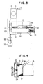
- the aforesaid ink-film forming unit (10) has an electromagnetic coil (18) in its upper portion.
- the two terminals of the coil (18) are coupled to side walls (21) integral with magnetic pole plates (20) which are opposed to each other to form a slit (19) therebetween.
- the magnetic pole plates (20) extend downwardly and project at the fore ends thereof into an ink vessel (23) where magnetic ink (22) is stored.
- a voltage of 0.7 to 1.0 volt is applied to the electromagnetic coil (18) to produce an output of 150 ampere-turn.
- the magnetic ink (22) has a magnetic induction of 200 gauss and a viscosity of 20 cp or less.
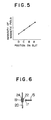
- the ink vessel (23) is so located that, upon energization of the electromagnetic coil (18), a magnetic ink film (24) is formed over the entirety of the slit (19). With respect to regions A, B, C and D of the pole plates (20), the magnetic gradient of the field intensity at the slit (19) rises from the region D toward the region A. Thus, it becomes possible to achieve satisfactory formation of a magnetic ink film (24) having a uniform thickness in the slit (19) without gravitational interference.
- the electromagnetic coil (18) is never energized when no printing operation is being performed, so that the magnetic ink (22) is not present in the slit (19) and consequently there arises no problem of clogging the slit (19) with a residuum derived from evaporation of the ink.
- the print density never varies due to the increased concentration of the magnetic ink (22).
- the electromagnetic coil (18) is energized, the magnetic ink (22) is attracted into the slit (19) and thereby forms an inkfilm (24).
- the tip (17) of each driven needle (15) is contacted with the magnetic ink (22) due to the presence of the ink film (24).
- an electromagnet with a coil (18) is employed as means for feeding the magnetic ink (22) to the slit (19)
- the structure may be so modified that the coil (18) is energized synchronously with turning on a power switch.
- the electromagnet may be replaced with a permanent magnet.
- magnetic flux generation in the slit (19) can be controlled by shifting the permanent magnet toward or away from the pole plates (20).
- magnetic shield means such as an aluminum plate may be interposed between the permanent magnet and the pole plates (20).
- a proper magnetic gradient may be provided by increasing the slit width gradually from the upper portion toward the lower portion.
Landscapes
- Impact Printers (AREA)
Claims (9)
Applications Claiming Priority (2)
| Application Number | Priority Date | Filing Date | Title |
|---|---|---|---|
| JP28899/83 | 1983-02-22 | ||
| JP58028899A JPS59152874A (ja) | 1983-02-22 | 1983-02-22 | ドツトプリンタ |
Publications (3)
| Publication Number | Publication Date |
|---|---|
| EP0117123A2 EP0117123A2 (fr) | 1984-08-29 |
| EP0117123A3 EP0117123A3 (en) | 1985-04-10 |
| EP0117123B1 true EP0117123B1 (fr) | 1987-11-19 |
Family
ID=12261249
Family Applications (1)
| Application Number | Title | Priority Date | Filing Date |
|---|---|---|---|
| EP84300970A Expired EP0117123B1 (fr) | 1983-02-22 | 1984-02-15 | Alimentation en encre pour imprimante par points |
Country Status (4)
| Country | Link |
|---|---|
| US (1) | US4813797A (fr) |
| EP (1) | EP0117123B1 (fr) |
| JP (1) | JPS59152874A (fr) |
| DE (1) | DE3467532D1 (fr) |
Families Citing this family (3)
| Publication number | Priority date | Publication date | Assignee | Title |
|---|---|---|---|---|
| US4696589A (en) * | 1984-10-26 | 1987-09-29 | Tokyo Electric Co., Ltd. | Ink-dot printer |
| JPH0720723B2 (ja) * | 1988-12-09 | 1995-03-08 | 株式会社精工舎 | 印字ヘッドの取付構造 |
| US8894181B2 (en) * | 2010-01-04 | 2014-11-25 | King Saud University | Printing system and method |
Family Cites Families (6)
| Publication number | Priority date | Publication date | Assignee | Title |
|---|---|---|---|---|
| US2842244A (en) * | 1955-04-04 | 1958-07-08 | Charles H Gibson | Machine operator for electric typewriters |
| US3596285A (en) * | 1969-07-11 | 1971-07-27 | Teletype Corp | Liquid metal recorder |
| JPS5275A (en) * | 1975-06-20 | 1977-01-05 | Matsushita Electric Ind Co Ltd | Dehydrating washing machine |
| DE2546835C3 (de) * | 1975-10-18 | 1980-11-06 | Philips Patentverwaltung Gmbh, 2000 Hamburg | Druckeinrichtung mit in Längsrichtung verschiebbaren Drucknadeln |
| US4279523A (en) * | 1979-09-14 | 1981-07-21 | International Business Machines Corporation | Power recovery apparatus for an electric typewriter |
| JPS5942972A (ja) * | 1982-09-06 | 1984-03-09 | Oki Electric Ind Co Ltd | インパクト式プリンタ |
-
1983
- 1983-02-22 JP JP58028899A patent/JPS59152874A/ja active Pending
-
1984
- 1984-02-15 DE DE8484300970T patent/DE3467532D1/de not_active Expired
- 1984-02-15 EP EP84300970A patent/EP0117123B1/fr not_active Expired
-
1986
- 1986-06-30 US US06/880,091 patent/US4813797A/en not_active Expired - Fee Related
Also Published As
| Publication number | Publication date |
|---|---|
| US4813797A (en) | 1989-03-21 |
| DE3467532D1 (en) | 1987-12-23 |
| EP0117123A2 (fr) | 1984-08-29 |
| JPS59152874A (ja) | 1984-08-31 |
| EP0117123A3 (en) | 1985-04-10 |
Similar Documents
| Publication | Publication Date | Title |
|---|---|---|
| EP0117123B1 (fr) | Alimentation en encre pour imprimante par points | |
| US4552469A (en) | Ink dot printer | |
| EP0179493B1 (fr) | Imprimante à points d'encre | |
| US4562446A (en) | Ink-dot printer with magnetic ink attracting and retention preventing means | |
| JPH0254785B2 (fr) | ||
| EP0179494B1 (fr) | Imprimante à points d'encre | |
| EP0129165A2 (fr) | Imprimante par points d'encre | |
| JPS59155061A (ja) | インクドツトプリンタ | |
| JP2855792B2 (ja) | ドットラインプリンタ | |
| US5433538A (en) | Wire guide in a wire dot print head | |
| JPS60166467A (ja) | インクドツトプリンタ | |
| JPS59182749A (ja) | インクドツトプリンタ | |
| JPS63295271A (ja) | ドットプリンタ | |
| JPS61110566A (ja) | インクドツトプリンタ | |
| JPH0324347B2 (fr) | ||
| JPH0316909B2 (fr) | ||
| JP3964942B2 (ja) | ハンマ機構部 | |
| JPS61104864A (ja) | インクドツトプリンタ | |
| JPS60187561A (ja) | シリアル型ドツトプリンタ | |
| JPH0429B2 (fr) | ||
| JPS59190864A (ja) | インクドツトプリンタ | |
| JPS61112655A (ja) | インクドツトプリンタ | |
| JPS61106267A (ja) | インクドツトプリンタ | |
| JPS61102266A (ja) | インクドツトプリンタ | |
| JPS61104865A (ja) | インクドツトプリンタ |
Legal Events
| Date | Code | Title | Description |
|---|---|---|---|
| PUAI | Public reference made under article 153(3) epc to a published international application that has entered the european phase |
Free format text: ORIGINAL CODE: 0009012 |
|
| AK | Designated contracting states |
Designated state(s): DE FR GB |
|
| PUAL | Search report despatched |
Free format text: ORIGINAL CODE: 0009013 |
|
| AK | Designated contracting states |
Designated state(s): DE FR GB |
|
| 17P | Request for examination filed |
Effective date: 19850628 |
|
| 17Q | First examination report despatched |
Effective date: 19860430 |
|
| GRAA | (expected) grant |
Free format text: ORIGINAL CODE: 0009210 |
|
| AK | Designated contracting states |
Kind code of ref document: B1 Designated state(s): DE FR GB |
|
| REF | Corresponds to: |
Ref document number: 3467532 Country of ref document: DE Date of ref document: 19871223 |
|
| ET | Fr: translation filed | ||
| PLBE | No opposition filed within time limit |
Free format text: ORIGINAL CODE: 0009261 |
|
| STAA | Information on the status of an ep patent application or granted ep patent |
Free format text: STATUS: NO OPPOSITION FILED WITHIN TIME LIMIT |
|
| 26N | No opposition filed | ||
| PGFP | Annual fee paid to national office [announced via postgrant information from national office to epo] |
Ref country code: FR Payment date: 19930126 Year of fee payment: 10 |
|
| PGFP | Annual fee paid to national office [announced via postgrant information from national office to epo] |
Ref country code: GB Payment date: 19930201 Year of fee payment: 10 |
|
| PGFP | Annual fee paid to national office [announced via postgrant information from national office to epo] |
Ref country code: DE Payment date: 19930330 Year of fee payment: 10 |
|
| PG25 | Lapsed in a contracting state [announced via postgrant information from national office to epo] |
Ref country code: GB Effective date: 19940215 |
|
| GBPC | Gb: european patent ceased through non-payment of renewal fee |
Effective date: 19940215 |
|
| PG25 | Lapsed in a contracting state [announced via postgrant information from national office to epo] |
Ref country code: FR Effective date: 19941031 |
|
| PG25 | Lapsed in a contracting state [announced via postgrant information from national office to epo] |
Ref country code: DE Effective date: 19941101 |
|
| REG | Reference to a national code |
Ref country code: FR Ref legal event code: ST |