EP0117428B1 - Weichpuppe - Google Patents
Weichpuppe Download PDFInfo
- Publication number
- EP0117428B1 EP0117428B1 EP84100740A EP84100740A EP0117428B1 EP 0117428 B1 EP0117428 B1 EP 0117428B1 EP 84100740 A EP84100740 A EP 84100740A EP 84100740 A EP84100740 A EP 84100740A EP 0117428 B1 EP0117428 B1 EP 0117428B1
- Authority
- EP
- European Patent Office
- Prior art keywords
- ball
- soft
- bearing
- doll
- doll according
- Prior art date
- Legal status (The legal status is an assumption and is not a legal conclusion. Google has not performed a legal analysis and makes no representation as to the accuracy of the status listed.)
- Expired
Links
- 241001293250 Lagascea decipiens Species 0.000 claims abstract description 5
- 125000006850 spacer group Chemical group 0.000 claims description 6
- 210000001015 abdomen Anatomy 0.000 claims description 2
- 210000002414 leg Anatomy 0.000 description 28
- 230000006835 compression Effects 0.000 description 3
- 238000007906 compression Methods 0.000 description 3
- 238000003780 insertion Methods 0.000 description 2
- 230000037431 insertion Effects 0.000 description 2
- 210000000689 upper leg Anatomy 0.000 description 2
- 230000006978 adaptation Effects 0.000 description 1
- 230000015572 biosynthetic process Effects 0.000 description 1
- 239000002657 fibrous material Substances 0.000 description 1
- 230000000149 penetrating effect Effects 0.000 description 1
- 230000036316 preload Effects 0.000 description 1
- 230000000087 stabilizing effect Effects 0.000 description 1
Images
Classifications
-
- A—HUMAN NECESSITIES
- A63—SPORTS; GAMES; AMUSEMENTS
- A63H—TOYS, e.g. TOPS, DOLLS, HOOPS OR BUILDING BLOCKS
- A63H3/00—Dolls
- A63H3/36—Details; Accessories
- A63H3/46—Connections for limbs
Definitions
- the invention relates to a soft doll with a stabilizing inner frame of the doll's body, which consists of a longitudinal part held in the doll's head and a seated at its lower end, facing outwards, at the ends of which a ball joint is arranged, which is attached to the leg with a holding piece Connection is established.
- the inner frame has a Y-shape; at the lower end of the longitudinal part there are two legs pointing obliquely downwards and outwards, to the free end of which an outward-pointing ball joint is attached, the ball of which is located in the holding piece of the leg.
- This known configuration is disadvantageous in several respects.
- no thigh can be formed on her leg, which creates an unnatural appearance and severely limits the mobility of the leg, because the body shell in the joint area has only a very small area available for the deformation that occurs during leg movement; there are even unwanted resetting movements.
- leg movement does not result in a normal step because the legs perform an outward-swinging circular movement due to the obliquely outward arrangement of the ball joint.
- Rotating the legs around their longitudinal axis is associated - if at all possible - with an unnatural lifting of the foot from the floor; an independent standing of the soft doll is completely impossible.
- the invention has for its object to provide a soft doll, which comes as close as possible to the human role model both in appearance and in terms of mobility or the course of movement of the legs, which should therefore be pivotable in any plane and fixable in all positions that can be achieved;
- the chosen design should be easy to install.
- this object is achieved according to the invention in that the bearing part is arranged transversely to the longitudinal part and the ball of the ball-and-socket joint, the bearing shell of which is aligned parallel to the longitudinal part, is connected to the holding piece via a connecting part which is also directed downward.
- connection of a connecting part between the ball of the ball joint and the holding piece of the leg allows the formation of a thigh.
- the legs themselves - especially by aligning the bearing shell of the ball joints parallel to the longitudinal part - can be swiveled on all sides, whereby a correspondingly strong preload of the ball in the bearing shell ensures that the position reached when the swiveling movement of the leg stops is automatically fixed.
- the assembly of the ball joint - connecting part - holding piece for the purpose of insertion into the doll body and attachment of the legs is very easy.
- the holding piece is freely rotatable with respect to the connecting part about its longitudinal axis. In this way it is possible to rotate the legs about their longitudinal axis in addition to pivoting by means of the ball-and-socket joint, although this rotational movement is limited by the fastening of the outer shell of the doll body to the upper outer edge of the legs.
- the bearing shell of the ball and socket joint have a slit on its side facing the belly of the doll's body, the width of which is greater than that of the connecting part. Due to this configuration, the legs - e.g. when performing a walking or Schreitbe movement of the doll can be pivoted far up because the connecting part does not abut the lower edge of the bearing shell, but enters the slot. If, according to a further advantageous feature of the invention, this slit is provided in its lower region with an insertion zone which widens downwards, the legs can be pivoted upwards even when the latter is adjusted laterally.
- the bearing shell has a hollow bearing pin projecting upwards from its top, in which a helical compression spring acting on the ball is accommodated, at the lower end of which a ball socket is provided.
- This helical compression spring gives the ball the pre-tension required within the joint to fix a selected leg position.
- the connecting part consists of a screw fastened to the ball and a spacer sleeve, the bolt of the screw penetrating a central opening in the holding piece and being supported on the rear side thereof by the head of the screw; the spacer sleeve and the holding piece can also be formed in one piece.
- the bearing part of the inner frame can be separated from its longitudinal part, which in turn facilitates the assembly of the doll and, moreover, enables adaptation to different doll sizes.
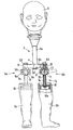
- the drawing shows a doll's head 1, the is connected via an inner frame 2 to doll legs 3a and 3b, of which the leg 3b has a position which is rotated or offset by 90 ° to the outside relative to that of the leg 3a.
- the inner frame 2 consists of a longitudinal part 2a and a bearing part 2b, the longitudinal part 2a being held in a central bearing recess 4 of the bearing part 2b and being secured by means of a snap ring 2a '; Longitudinal part 2a and bearing part 2b are releasably connected to each other.
- a ball joint 5a and 5b is attached to the ends of the bearing part 2b.
- Each of these two ball joints consists of a two-part bearing shell and a ball 7 rotatably held therein.
- the two parts 6a and 6b of each bearing shell 6 are connected to one another by means of screws 6c.
- the lower part 6a is dimensioned so that the ball 7 protrudes therefrom; on the upper part 6b there is a bearing pin 6d which projects upwards and penetrates a bearing recess 8 of the bearing parts 2b and which is secured by means of a snap ring 2b '.
- the bearing shell 6 On its front side, the bearing shell 6 has a slot 9 with a region that widens downwards.
- a helical compression spring 10 is accommodated, which is supported on the ball 7 via a ball socket 11 provided at its lower end and presses it against the lower part 6a of the bearing shell 6.
- connection part 12 is assigned to the area of the ball protruding from the lower part 6a of the bearing shell 6, which connects the leg 3a or 3b to the corresponding ball joint 5a or 5b.
- the connecting part 12 consists of a screw 13 and a spacer sleeve 14 pushed over the bolt thereof.
- the free end of the screw 13 is screwed into the ball 7; its bolt penetrates a holding piece 15 mounted in the upper end region of the legs 3a and 3b, against the back of which the screw 13 is supported by means of its head 13a.
- the spacer sleeve 14 ensures a constant distance between the ball joints 5a and 5b and the associated legs 3a and 3b, without impeding their rotation about the longitudinal axis of the screw 13.
- the doll design described above brings considerable advantages in terms of assembly.
- the legs 3a and 3b are sewn onto the inside of the doll's outer shell (not shown in the drawing).
- the holding piece 15 with the connecting part 12 and ball joint 5a or 5b are inserted into each leg 3a and 3b and the legs 3a and 3b are pulled outwards.
- the inner frame 2 is inserted through the neck opening of the outer shell, placed with the bearing part 2b on the journal 6d of the ball joints 5a and 5b and locked with these by attaching the snap rings 2b '.
- the outer shell or doll body is filled - e.g. with a soft fiber material - and putting on the doll's head 1.
Landscapes
- Toys (AREA)
Description
- Die Erfindung betrifft eine Weichpuppe mit einem den Puppenkörper stabilisierenden Innengerüst, das aus einem im Puppenkopf gehaltenen Längsteil und einem an dessen unterem Ende ansitzenden, nach außen weisenden Lagerteil besteht, an dessen Enden je ein Kugelgelenk angeordnet ist, das über ein Haltestück mit dem Bein in Verbindung steht.
- Bei dieser aus der US-A- 4 268 991 bekannten Weichpuppe besitzt das Innengerüst Y-Form; am unteren Ende des Längsteils sitzen zwei schräg nach unten und außen weisende Schenkel an, an deren freiem Ende ein nach außen gerichtetes Kugelgelenk befestigt ist, dessen Kugel sich im Haltestück des Beins befindet. Diese bekannte Ausgestaltung ist in mehrfacher Hinsicht nachteilig. So läßt sich bei ihr am Bein kein Oberschenkel ausbilden, was ein unnatürliches Aussehen schafft und die Beweglichkeit des Beins stark einschränkt, weil die Körperhülle im Gelenkbereich für ihre während der Beinbewegung auftretende Verformung nur eine sehr kleine Fläche zur Verfügung hat; es kommt sogar zu ungewollten Rückstellbewegungen. Auch ergibt die Beinbewegung keinen normalen Schritt, weil die Beine infolge der schräg nach außen weisenden Anordnung des Kugelgelenks eine nach außen schwingende kreisende Bewegung ausführen. Ein Drehen der Beine um ihre Längsachse ist - sofern überhaupt möglich - mit einem unnatürlichen Abheben des Fußes vom Boden verbunden; ein selbständiges Stehen der Weichpuppe ist völlig ausgeschlossen.
- Der Erfindung liegt die Aufgabe zugrunde, eine Weichpuppe zu schaffen, welche dem menschlichen Vorbild sowohl im Aussehen als auch hinsichtlich der Beweglichkeit bzw. des Bewegungsablaufs der Beine möglichst nahekommt, die deshalb in beliebigen Ebenen verschwenkbar und in sämtlichen dabei erreichbaren Stellungen fixierbar sein sollen; außerdem soll die dafür gewählte konstruktive Ausgestaltung einfach montierbar sein.
- Ausgehend von einer Weichpuppe der eingangs beschriebenen Gattung wird diese Aufgabe erfindungsgemäß dadurch gelöst, daß das Lagerteil zum Längsteil querverlaufend angeordnet und die Kugel des Kugelgelenks, dessen Lagerschale parallel zum Längsteil ausgerichtet ist, über ein ebenfalls nach unten gerichtetes Verbindungsteil mit dem Haltestück verbunden ist.
- Die Einschaltung eines Verbindungsteils zwischen der Kugel des Kugelgelenks und dem Haltestück des Beins erlaubt die Ausbildung eines Oberschenkels. Die Beine selbst sind - vor allem durch die Ausrichtung der Lagerschale der Kugelgelenke parallel zum Längsteil - allseitig versch wenkbar, wobei eine entsprechend starke Vorspannung der Kugel in der Lagerschale dafür sorgt, daß die beim Aufhören der Schwenkbewegung des Beins erreichte Stellung automatisch fixiert ist. Die Montage der Baueinheit Kugelgelenk - Verbindungsteil - Haltestück zwecks Einbringung in den Puppenkörper und Befestigung der Beine ist denkbar einfach.
- Gemäß einem weiteren wesentlichen Merkmal der Erfindung ist das Haltestück inbezug auf das Verbindungsteil um dessen Längsachse frei drehbar. Auf diese Weise ist es möglich, die Beine zusätzlich zu einer mittels des Kugelgelenks erfolgenden Verschwenkung auch noch um ihre Längsachse zu drehen, wobei diese Drehbewegung allerdings durch die Befestigung der Außenhülle des Puppenkörpers am oberen Außenrand der Beine begrenzt wird.
- Es empfiehlt sich, die Lagerschale des Kugelgelenks auf ihrer dem Bauch des Puppenkörpers zugewandten Seite eine Schlitzung aufweisen zu lassen, deren Breite größer als die des Verbindungsteils ist. Aufgrund dieser Ausgestaltung können die Beine - z.B. bei Durchführung einer Geh- bzw. Schreitbe wegung der Puppebeliebig weit nach oben geschwenkt werden, weil das Verbindungsteil dabei nicht gegen den unteren Rand der Lagerschale stößt, sondern in die Schlitzung eintritt. Wenn diese Schlitzung gemäß einem weiteren vorteilhaften Merkmal der Erfindung in ihrem unteren Bereich mit einer sich nach unten erweiternden Einführungszone versehen ist, läßt sich ein Aufwärtsschwenken der Beine auch bei seitlicher Verstellung derselben bewerkstelligen.
- Bezüglich der konstruktiven Ausgestaltung des Kugelgelenks hat es sich als zweckmäßig erwiesen, wenn die Lagerschale einen von ihrer Oberseite nach oben vorstehenden hohlen Lagerzapfen aufweist, in dem eine die Kugel beaufschlagende Schraubendruckfeder untergebracht ist, an deren unterem Ende eine Kugelpfanne vorgesehen ist. Diese Schraubendruckfeder erteilt der Kugel die für das Fixieren einer gewählten Beinstellung erforderliche Vorspannung innerhalb des Gelenks. Dabei bietet es montagetechnische Vorteile, wenn das Kugelgelenk mit dem Lagerteil lösbar verbunden ist, was sich z weckmäßigerweise derart verwirklichen läßt, daß der Lagerzapfen in einer Lagerausnehmung des Lagerteils gehalten ist.
- In vorteilhafter Weise besteht das Verbindungsteil aus einer an der Kugel befestigten Schraube und einer Distanzhülse, wobei der Bolzen der Schraube eine zentrale Öffnung im Haltestück durchdringt und auf dessen Rückseite mittels des Kopfs der Schraube abgestützt ist; auch können die Distanzhülse und das Haltestück einstückig ausgebildet sein.
- In Fortführung des Erfindungsgedankens ist das Lagerteil des Innengerüsts von dessen Längsteil trennbar, wodurch wiederum die Montage der Puppe erleichtert und darüber hinaus eine Anpassung an unterschiedliche Puppengrößen möglich wird.
- In der Zeichnung ist ein bevorzugtes Ausführungsbeispiel der Erfindung dargestellt.
- Die Zeichnung zeigt einen Puppenkopf 1, der über ein Innengerüst 2 mit Puppenbeinen 3a und 3b verbunden ist, von denen das Bein 3b eine Stellung aufweist, die gegenüber der des Beins 3a um 90° nach außen gedreht bzw. versetzt ist. Das Innengerüst 2 besteht aus einem Längsteil 2a und einem Lagerteil 2b, wobei das Längsteil 2a in einer zentralen Lagerausnehmung 4 des Lagerteils 2b gehalten und mittels eines Sprengrings 2a' gesichert ist; Längsteil 2a und Lagerteil 2b sind also lösbar miteinander verbunden.
- An den Enden des Lagerteils 2b ist je ein Kugelgelenk 5a und 5b angebracht. Jedes dieser beiden Kugelgelenke besteht aus einer zweiteiligen Lagerschale und einer darin drehbar gehaltenen Kugel 7. Die beiden Teile 6a und 6b jeder Lagerschale 6 sind mittels Schrauben 6c miteinander verbunden. Das untere Teil 6a ist so bemessen, daß die Kugel 7 daraus vorsteht; am oberen Teil 6b ist ein nach oben vorstehender, eine Lagerausnehmung 8 der Lagerteils 2b durchdringender Lagerzapfen 6d vorgesehen, der mittels eines Sprengrings 2b' gesichert ist. Auf ihrer Vorderseite weist die Lagerschale 6 eine Schlitzung 9 mit einem sich nach unten erweiternden Bereich auf.
- Im hohlen Lagerzapfen 6d ist eine Schraubendruckfeder 10 untergebracht, die sich über eine an ihrem unteren Ende vorgesehene Kugelpfanne 11 auf der Kugel 7 abstützt und diese gegen das untere Teil 6a der Lagerschale 6 anpreßt.
- Dem aus dem unteren Teil 6a der Lagerschale 6 vorstehenden Bereich der Kugel ist ein Verbindungsteil 12 zugeordnet, welches das Bein 3a bzw. 3b an das entsprechende Kugelgelenk 5a bzw. 5b anschließt. Das Verbindungsteil 12 besteht aus einer Schraube 13 und einer über deren Bolzen geschobenen Distanzhülse 14. Die Schraube 13 ist mit ihrem freien Ende in die Kugel 7 eingeschraubt; ihr Bolzen durchdringt ein im oberen Endbereich der Beine 3a und 3b gelagertes Haltestück 15, gegen dessen Rückseite sich die Schraube 13 mittels ihres Kopfs 13a abstützt. Die Distanzhülse 14 sorgt für einen stets gleichbleibenden Abstand zwischen den Kugelgelenken 5a bzw. 5b und den zugehörigen Beinen 3a bzw. 3b, ohne deren Drehung um die Längsachse der Schraube 13 zu behindern.
- Die vorstehend beschriebene Puppengestaltung bringt erhebliche montagetechnische Vorteile mit sich. Zunächst werden die Beine 3a und 3b von der Innenseite der - in der Zeichnung nicht dargestellten - Außenhülle der Puppe her an dieser angenäht. Danach werden in jedes Bein 3a und 3b das Haltestück 15 mit Verbindungsteil 12 und Kugelgelenk 5a bzw. 5b eingesetzt und die Beine 3a und 3b nach außen gezogen. Im Anschluß daran wird das Innengerüst 2 durch die Halsöffnung der Außenhülle in diese eingeführt, mit dem Lagerteil 2b auf die Lagerzapfen 6d der Kugelgelenke 5a und 5b aufgesetzt und mit diesen durch Anbringen der Sprengringe 2b' arretiert. Abschließend erfolgt dann die Füllung der Außenhülle bzw. des Puppenkörpers - z.B. mit einem weichen Fasermaterial - und das Aufsetzen des Puppenkopfs 1.
Claims (12)
Priority Applications (1)
| Application Number | Priority Date | Filing Date | Title |
|---|---|---|---|
| AT84100740T ATE26403T1 (de) | 1983-01-29 | 1984-01-25 | Weichpuppe. |
Applications Claiming Priority (2)
| Application Number | Priority Date | Filing Date | Title |
|---|---|---|---|
| DE3302995A DE3302995C2 (de) | 1983-01-29 | 1983-01-29 | Weichpuppe |
| DE3302995 | 1983-01-29 |
Publications (2)
| Publication Number | Publication Date |
|---|---|
| EP0117428A1 EP0117428A1 (de) | 1984-09-05 |
| EP0117428B1 true EP0117428B1 (de) | 1987-04-08 |
Family
ID=6189537
Family Applications (1)
| Application Number | Title | Priority Date | Filing Date |
|---|---|---|---|
| EP84100740A Expired EP0117428B1 (de) | 1983-01-29 | 1984-01-25 | Weichpuppe |
Country Status (3)
| Country | Link |
|---|---|
| EP (1) | EP0117428B1 (de) |
| AT (1) | ATE26403T1 (de) |
| DE (1) | DE3302995C2 (de) |
Cited By (4)
| Publication number | Priority date | Publication date | Assignee | Title |
|---|---|---|---|---|
| USD1009170S1 (en) | 2023-07-13 | 2023-12-26 | Cca And B, Llc | Doll stand |
| USD1009169S1 (en) | 2023-07-13 | 2023-12-26 | Cca And B, Llc | Doll stand |
| USD1009171S1 (en) | 2023-07-13 | 2023-12-26 | Cca And B, Llc | Doll stand |
| USD1047019S1 (en) | 2023-10-24 | 2024-10-15 | Cca And B, Llc | Doll stand |
Families Citing this family (4)
| Publication number | Priority date | Publication date | Assignee | Title |
|---|---|---|---|---|
| DK157062C (da) * | 1985-12-04 | 1990-03-26 | Lego As | Legetoejsfigur med bevaegelige kropsdele |
| US4790789A (en) * | 1987-05-22 | 1988-12-13 | Mathis Michael S | Toy figure having adjustably movable joints |
| US5257873A (en) * | 1992-04-06 | 1993-11-02 | Abbat Jean Pierre | Articulated doll joint |
| US9056258B2 (en) | 2010-01-29 | 2015-06-16 | Mattel, Inc. | Toy figures |
Family Cites Families (9)
| Publication number | Priority date | Publication date | Assignee | Title |
|---|---|---|---|---|
| DE382588C (de) * | 1923-10-04 | Florig & Otto | Allseitig bewegliches Gelenk fuer Holzpuppen | |
| DE162856C (de) * | ||||
| US1359030A (en) * | 1919-06-14 | 1920-11-16 | Cabana Charles | Ball-and-socket joint for dolls, &c. |
| DE402482C (de) * | 1923-10-18 | 1924-09-16 | Huck Fa H | Gerippe fuer Gliederpuppen und andere gegliederte Spielzeuge |
| US1746839A (en) * | 1929-03-13 | 1930-02-11 | Main Toy Company | Toy builders |
| US2129421A (en) * | 1936-08-11 | 1938-09-06 | Landy R Hales | Manikin and method of making the same |
| US2593187A (en) * | 1950-01-30 | 1952-04-15 | Riechelson Morris | Walking doll |
| FR1225787A (fr) * | 1959-02-18 | 1960-07-04 | Huard Ets | Perfectionnement aux poupées |
| US4268991A (en) * | 1979-02-09 | 1981-05-26 | The Quaker Oats Company | Soft flexible articulated doll |
-
1983
- 1983-01-29 DE DE3302995A patent/DE3302995C2/de not_active Expired
-
1984
- 1984-01-25 EP EP84100740A patent/EP0117428B1/de not_active Expired
- 1984-01-25 AT AT84100740T patent/ATE26403T1/de not_active IP Right Cessation
Cited By (4)
| Publication number | Priority date | Publication date | Assignee | Title |
|---|---|---|---|---|
| USD1009170S1 (en) | 2023-07-13 | 2023-12-26 | Cca And B, Llc | Doll stand |
| USD1009169S1 (en) | 2023-07-13 | 2023-12-26 | Cca And B, Llc | Doll stand |
| USD1009171S1 (en) | 2023-07-13 | 2023-12-26 | Cca And B, Llc | Doll stand |
| USD1047019S1 (en) | 2023-10-24 | 2024-10-15 | Cca And B, Llc | Doll stand |
Also Published As
| Publication number | Publication date |
|---|---|
| DE3302995C2 (de) | 1986-07-10 |
| DE3302995A1 (de) | 1984-08-09 |
| EP0117428A1 (de) | 1984-09-05 |
| ATE26403T1 (de) | 1987-04-15 |
Similar Documents
| Publication | Publication Date | Title |
|---|---|---|
| DE2700969C3 (de) | Beinpaarlagerung in einer zusammensetzbaren Spielfigur | |
| DE19927244C2 (de) | Armlehnen-Gelenknuß für Behinderten-Stuhl und diese Gelenknuß verwendender Stuhl | |
| DE69829820T2 (de) | Untersuchungstisch, insbesondere für Anlagen zur Bilderzeugung mittels magnetischer Kernresonanz | |
| EP1112731B1 (de) | Therapiegerät | |
| EP0452636B1 (de) | Aufhängevorrichtung für ein Gerät an einem Fahrzeug | |
| CH365883A (de) | Stativ-Neigekopf mit schwenkbarem Stielgriff | |
| EP1849378B1 (de) | Vorrichtung zur Lehnenbefestigung | |
| DE2041468A1 (de) | Puppe mit angelenkten Gliedern | |
| DE602004009480T2 (de) | Mit einem kinder-sportwagen verbindbare rollenplattenform | |
| DE3005202C2 (de) | Vorrichtung zum Steuern der Schwenkbewegung der Kopfstütze eines Behandlungstisches oder -stuhls | |
| DE3444216A1 (de) | Kopfstuetze | |
| DE3302995C2 (de) | Weichpuppe | |
| DE859360C (de) | Verstellbarer Sitz- und Liegestuhl | |
| CH282569A (de) | Gliederpuppe, insbesondere für Schaufenster, Ausstellungen usw. | |
| DE1957228B2 (de) | Kuppelglied fuer ein mit einer geraeteanbauvorrichtung verbindbares anbaugeraet | |
| DE3150765A1 (de) | Befestigungsvorrichtung zur schwenkbaren befestigung eines gegenstands, insbesondere haltegriffs, an einer wand o.dgl. | |
| DE2258206A1 (de) | Anhaengevorrichtung | |
| DE19508907C1 (de) | Schwenkbeschlag für eine Rücken- und Kopfstütze eines Matratzenrahmens | |
| DE1963743A1 (de) | Puppe mit elastisch verbundenen Gliedern | |
| DE4410439C2 (de) | Unterarmorthese mit einem Mehrrichtungskugelgelenk | |
| DE3821233C2 (de) | Neigbarer Sitz für Kinder | |
| DE3122299A1 (de) | Fahrzeugsitz, insbesondere fuer flugzeuge und omnibusse | |
| DE3008011A1 (de) | Kinder-sportwagen | |
| DE69907086T2 (de) | Zusammenklappbarer Fahrradständer | |
| DE19724577C1 (de) | Lenkrolle |
Legal Events
| Date | Code | Title | Description |
|---|---|---|---|
| PUAI | Public reference made under article 153(3) epc to a published international application that has entered the european phase |
Free format text: ORIGINAL CODE: 0009012 |
|
| AK | Designated contracting states |
Designated state(s): AT BE CH FR GB IT LI NL SE |
|
| ITCL | It: translation for ep claims filed |
Representative=s name: MODIANO & ASSOCIATI S.R.L. |
|
| 17P | Request for examination filed |
Effective date: 19840827 |
|
| EL | Fr: translation of claims filed | ||
| GRAA | (expected) grant |
Free format text: ORIGINAL CODE: 0009210 |
|
| AK | Designated contracting states |
Kind code of ref document: B1 Designated state(s): AT BE CH FR GB IT LI NL SE |
|
| REF | Corresponds to: |
Ref document number: 26403 Country of ref document: AT Date of ref document: 19870415 Kind code of ref document: T |
|
| ITF | It: translation for a ep patent filed | ||
| ET | Fr: translation filed | ||
| PLBE | No opposition filed within time limit |
Free format text: ORIGINAL CODE: 0009261 |
|
| STAA | Information on the status of an ep patent application or granted ep patent |
Free format text: STATUS: NO OPPOSITION FILED WITHIN TIME LIMIT |
|
| 26N | No opposition filed | ||
| PGFP | Annual fee paid to national office [announced via postgrant information from national office to epo] |
Ref country code: CH Payment date: 19901129 Year of fee payment: 8 |
|
| PGFP | Annual fee paid to national office [announced via postgrant information from national office to epo] |
Ref country code: SE Payment date: 19910117 Year of fee payment: 8 |
|
| PGFP | Annual fee paid to national office [announced via postgrant information from national office to epo] |
Ref country code: BE Payment date: 19910129 Year of fee payment: 8 |
|
| ITTA | It: last paid annual fee | ||
| PGFP | Annual fee paid to national office [announced via postgrant information from national office to epo] |
Ref country code: AT Payment date: 19910131 Year of fee payment: 8 |
|
| PG25 | Lapsed in a contracting state [announced via postgrant information from national office to epo] |
Ref country code: AT Effective date: 19920125 |
|
| PG25 | Lapsed in a contracting state [announced via postgrant information from national office to epo] |
Ref country code: SE Effective date: 19920126 |
|
| PG25 | Lapsed in a contracting state [announced via postgrant information from national office to epo] |
Ref country code: BE Effective date: 19920131 Ref country code: LI Effective date: 19920131 Ref country code: CH Effective date: 19920131 |
|
| BERE | Be: lapsed |
Owner name: FIRMA MAX ZAPF Effective date: 19920131 |
|
| REG | Reference to a national code |
Ref country code: CH Ref legal event code: PL |
|
| EUG | Se: european patent has lapsed |
Ref document number: 84100740.4 Effective date: 19920806 |
|
| PGFP | Annual fee paid to national office [announced via postgrant information from national office to epo] |
Ref country code: GB Payment date: 19960104 Year of fee payment: 13 |
|
| PGFP | Annual fee paid to national office [announced via postgrant information from national office to epo] |
Ref country code: FR Payment date: 19960116 Year of fee payment: 13 |
|
| PGFP | Annual fee paid to national office [announced via postgrant information from national office to epo] |
Ref country code: NL Payment date: 19960129 Year of fee payment: 13 |
|
| PG25 | Lapsed in a contracting state [announced via postgrant information from national office to epo] |
Ref country code: GB Effective date: 19970125 |
|
| PG25 | Lapsed in a contracting state [announced via postgrant information from national office to epo] |
Ref country code: NL Effective date: 19970801 |
|
| GBPC | Gb: european patent ceased through non-payment of renewal fee |
Effective date: 19970125 |
|
| PG25 | Lapsed in a contracting state [announced via postgrant information from national office to epo] |
Ref country code: FR Effective date: 19970930 |
|
| NLV4 | Nl: lapsed or anulled due to non-payment of the annual fee |
Effective date: 19970801 |
|
| REG | Reference to a national code |
Ref country code: FR Ref legal event code: ST |