EP0117560A2 - Système de serrure de porte - Google Patents
Système de serrure de porte Download PDFInfo
- Publication number
- EP0117560A2 EP0117560A2 EP84102037A EP84102037A EP0117560A2 EP 0117560 A2 EP0117560 A2 EP 0117560A2 EP 84102037 A EP84102037 A EP 84102037A EP 84102037 A EP84102037 A EP 84102037A EP 0117560 A2 EP0117560 A2 EP 0117560A2
- Authority
- EP
- European Patent Office
- Prior art keywords
- lock
- lever
- control
- unlock
- door
- Prior art date
- Legal status (The legal status is an assumption and is not a legal conclusion. Google has not performed a legal analysis and makes no representation as to the accuracy of the status listed.)
- Withdrawn
Links
- 230000000717 retained effect Effects 0.000 claims description 2
- 230000006835 compression Effects 0.000 description 5
- 238000007906 compression Methods 0.000 description 5
- JEIPFZHSYJVQDO-UHFFFAOYSA-N iron(III) oxide Inorganic materials O=[Fe]O[Fe]=O JEIPFZHSYJVQDO-UHFFFAOYSA-N 0.000 description 4
- 238000010276 construction Methods 0.000 description 2
- 238000010586 diagram Methods 0.000 description 1
- 229920003002 synthetic resin Polymers 0.000 description 1
- 239000000057 synthetic resin Substances 0.000 description 1
Images



Classifications
-
- E—FIXED CONSTRUCTIONS
- E05—LOCKS; KEYS; WINDOW OR DOOR FITTINGS; SAFES
- E05B—LOCKS; ACCESSORIES THEREFOR; HANDCUFFS
- E05B77/00—Vehicle locks characterised by special functions or purposes
- E05B77/46—Locking several wings simultaneously
- E05B77/48—Locking several wings simultaneously by electrical means
Definitions
- the present invention relates to a door lock system applicable to doors of a vehicle such as an automobile, and more specifically to a door lock system arranged to lock and unlock a plurality of doors all together.
- Japanese Patent publication Sho 46-15882 discloses one example of such a door lock system.
- a lock lever for locking and unlocking a door is resiliently connected, though a compression spring, with a control lever which is moved by a key lock device and an inside lock knob of the door.
- the control lever is arranged to swing beyond a range in which the lock lever can swing.
- a position sensor is connected with the control lever, and commands another door lock unit to lock or unlock another door when the control lever is moved beyond the range of the lock lever.
- this door lock system is disadvantageous in that its construction is complicated. Furthermore, in order to actuate the position sensor, the key lock device or the inside lock knob must be moved with a force strong enough to move the control lever against the force of the compression spring.
- This feature significantly deteriorates a feeling of operating the key lock device and the inside lock knob. Besides, this door lock system is easily affected by rust. When the lock lever becomes stiff because of rust, this door lock system tends to falls into a condition in which the control lever can only deflects the compression spring but cannot move the lock lever to the lock position, so that this door lock system is incapable of locking the door.
- the door lock system comprises a first assembly and actuating means.
- the first assembly comprises lock means, control means, positioning means and position sensing means.
- the lock means locks a first door when the lock means is in a lock position, and unlocks the first door when the lock means is in an unlock position.
- the control means is connected with the lock means for moving the lock means between the lock position and the unlock position.
- the control means is capable of moving between a lock control position and an unlock control position.
- the control means holds the lock means in the lock position when the control means is in the lock control position, and in the unlock position when the control means is in the unlock control position.
- the control means is capable of moving beyond the lock control position to a lock over position.
- the positioning means enables the control means to stop in the lock control position and the unlock control position.
- the position sensing means is connected with the control means for producing a lock signal when the control means is moved beyond the lock control position to the lock over position.
- the actuating means is connected with the position sensing means to receive the lock signal.
- the door lock system may be further arranged so that the control means is capable of moving beyond the unlock control position to an unlock over position, and that the position sensing means produces an unlock signal when the control means is moved beyond the unlock control position to the unlock over position.
- the actuating means is connected with a second assembly which is capable of locking and unlocking a second door.
- the actuating means actuates the second assembly to lock the second door in response to the lock signal produced by the position sensing means of the first assembly, and to unlock the second door in response to the unlock signal.
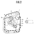
- FIGs. 1 to 7 One embodiment of the present invention is shown in Figs. 1 to 7.
- This door lock system has a hollow door lock case 1 of a synthetic resin, and a cover plate 2 and a base plate 3 between which the case 1 is sandwitched and fastened as a single unit.
- the case 1 and the cover plate 2 are formed with an opening 5 for receiving a striker 4 shown in Fig. 2.
- the striker 4 is fixed to a pillar (not shown).
- a forked latch 7 has a first furcation 7a and a second furcation 7b which both extend from a base portion.
- the forked latch 7 is rotatably mounted, at the base portion, on a shaft 6 in the case 1.
- the shaft 6 is positioned above the opening 5.
- a spring 8 is disposed between a projection 2a of the cover plate 2 and the forked latch 7. The spring 8 rotates or tends to rotate the latch 7 in an unlatch direction which is a counterclockwise direction as viewed in Fig. 2.
- the furcations 7a and 7b of the latch 7 can receive the striker 4 therebetween.
- a pawl 10 is disposed below the opening 5.
- the pawl 10 is rotatable from a detaining position shown by a solid line in Fig. 2 to a releasing position shown by a two-dot chain line in Fig. 2, and vice versa.
- the pawl 10 lies within the extent of the rotational movement of the furcations 7a and 7b of the latch 7.
- the pawl 10 lies outside the extent.
- the latch 7 can occupy a half latch position (shown by a one-dot chain line in Fig.
- a rotary plate 12 shown in Fig. 3 is fixed to the pawl 10.
- the pawl 10 is fixedly mounted on a shaft 10a which passes through the base plate 3 and has, at an end, the rotary plate 12 fixed thereto.
- the above-mentioned spring 13 is disposed between the rotary plate 12 and a projection 3b of the base plate 3.
- the spring 13 rotates or tends to rotate the rotary plate 12, the shaft 10a and the pawl 10 in the clockwise direction as viewed in Fig. 3.
- the rotary plate 12 has a bent portion 12a which is bent toward the base plate 3, and a projecting portion 12b.
- An outside handle lever 15 is mounted at the upper part of the base plate 3.
- the outside handle lever 15 is swingable on a shaft 14.
- a spring 16 applies, on the outside handle lever 15, a force tending to rotate the outside handle lever 15 in the clockwise direction in Fig. 3.
- One end of the outside handle lever 15 is connected with an outside handle rod 17 which is connected with an outside handle of the door (not shown).
- the outside handle lever 15 is formed with a support hole 18 lying between the shaft 14 and the swingable end connected with the outside handle rod 17.
- An inside handle lever 22 shown in Fig. 1 is rotatably mounted on a shaft 20.%
- the base plate 3 has a portion 3c which is bent perpendicularly.
- the shaft 20 is supported by this portion 3c of the base plate 3.
- the inside handle lever 22 is connected with an inside handle of the door (not shown) by an inside handle rod 24.
- a spring 25 is disposed between the portion 3c of the base plate 3 and the inside handle lever 22.
- the spring 25 applies a force tending to rotate the inside handle lever 22 in the clockwise direction as viewed in Fig. 1.
- the inside handle lever 22 has an operating portion 22a.
- the operating portion 22a lies under a follower portion 12c of the rotary plate 12.
- the inside handle lever 22 swings from a position shown by a solid line in Fig. 1 to a position shown by a two-dot chain line in Fig. 1. During this swing motion, the operating portion 22a of the inside handle lever 22 pushes up the follower portion 12c of the rotary plate 12.
- a lock knob lever 23 shown in Fig. 1 is rotatably mounted on a shaft 21, which is supported by the portion 3c of the base plate 3.
- the lock knob lever 23 is connected with an inside lock knob 26 by a lock knob rod 27.
- the lock knob lever 23 is swingable on the shaft 21 between an unlock position shown by a solid line and a lock position shown by a two-dot chain line in Fig. 1.
- a position sensor 29 is connected with the lock knob lever 23.
- the position sensor 29 has a lever 29a.
- the lever 29a is connected with one arm of the lock knob lever 23 by a rod 28, as shown in Fig. 1.
- the position sensor 29 is connected with actuators M 1 , M 2 and M 3 , as shown in Fig. 7.
- a key lever 31 shown in Fig. 3 is disposed at the lower part of the base plate 3.
- the key lever 31 is rotatably supported, at a middle portion, on a shaft 30.
- the key lever has a first end 31d which is sandwitched between furcations 23a and 23b of a forked end of the lock knob lever 23. Accordingly, the end 31d of the key lever 31 and the forked end of the lock knob lever 23 move up and down together.
- the key lever 31 has a second end 31e which is connected with a key lock unit (not shown) of the door by a key rod 33.
- the key lever 31 has an extended portion 31f, which has a pin 34 fixed thereto.
- a lock lever 19 shown in Fig. 3 has a first end 19a received in the above-mentioned support hole 18 of the outside handle lever 15, and a second end portion 19b having a slot 35 which receives the above-mentioned pin 34 of the key lever 31.
- the support hole 18 of the outside handle lever 15 swingably supports the first end 19a of the lock lever 19.
- the lock lever 19 is swingable about the first end 19a.
- the slot 35 is in the shape of a circular arc.
- the pin 34 is slidable in the slot 35.
- the lock lever 19 has an unlocking projection 19c and a bent edge 19d.
- the unlocking projection 19c lies near the bent portion 12a of the rotary plate 12.
- the bent edge 19d of the lock lever 19 lies near the projecting portion 12b of the rotary plate 12.
- the unlocking projection 19c of the lock lever 19 can push down the bent portion 12a of the rotary plate 12.
- the unlocking projection 19c is so apart from the bent portion 12a of the rotary plate 12 that the unlocking projection 19c cannot push down the bent portion 12a.
- the bent edge 19d of the lock lever 19 stands close to the projecting portion 12b of the rotary plate 12, and prevents the movement of the rotary plate 12.
- a positioning mechanism 32 shown in Fig. 4 is provided between the key lever 31 and the stationary base plate 3.
- the positioning mechanism 32 has a compression spring 32b retained in a case 32a fixed to the base plate 3.
- the compression spring 32b pushes a push member 32c against the key lever 31.
- the key lever 31 is formed with two recesses, an unlock recess 31a and a lock recess 31b.
- the recesses 31a and 31b are adjacent to each other, and lie on a circle along which a point fixed to the key lever 31 travels when the key lever 31 swings.
- the key lever 31 is further formed with a guide slope 31c adjacent to the lock recess 31b.
- the thus constructed door lock system can be put in three positions, an unlock position, a lock position and a lock over position.
- the unlock position is shown by solid line in Figs. 1, 3 and 4.
- the unlock recess 31a of the key lever 31 receives the push member 32c of the positioning mechanism 32, and the lock lever 19 is held in the position shown by the solid line in Fig. 3.
- the arm of the outside handle lever 15 pushes down the lock lever 19 to an unlatch position shown by a two-dot chain line in Fig. 3.
- the unlocking projection 19c of the lock lever 19 pushes down the bent portion 12a of the rotary plate 12, and by so doing, rotates the pawl 10 from the detaining position to the releasing position. Therefore, the latch 7 is released, and the door is put in an openable state.
- the lock position is shown by a two-dot chain line in Fig. 1, and solid lines in Figs. 5 and 6.
- the lock recess 31b of the key lever 31 receives the push member 32c, and the lock lever 19 is held in the position shown by the solid line in Fig. 5.
- the unlocking projection 19c of the lock lever 19 is away from the bent portion 12a of the rotary plate 12, so that one cannot move the pawl 10 by operating the outside handle.
- the bent edge 19d of the lock lever 19 prevents the rotary plate 12 from rotating in the counterclockwise direction as viewed in Fig. 5, by engaging with the projecting portion 12b of the rotary plate 12. Therefore, one cannot move the pawl 10 by operating the inside handle. Thus, the door is locked in this lock position.
- the lock over position is shown by one-dot chain lines in Figs. 1 and 5.
- the lock knob lever 23 and the key lever 31 can swing beyond the lock position to the lock over position.
- the push member 32c of the positioning mechanism 32 lies on the guide slope 31c of the key lever 31.
- the position sensor 29 is actuated, and causes the actuators M 1 , M 2 and M 3 to lock doors which are, respectively, connected with the actuators.
- the guide slope 31c produces a restoring force which returns or tends to return the lock knob lever 23 and the key lever 31 to the lock position. Therefore, the lock knob lever 23, the key lever 31 and the lock lever 19 return to the lock position when the inside lock knob or the key lock unit are set free.
- Fig. 8 shows another design of the positioning mechanism 32.
- the key lever 31 is further formed with a second guide slope 31g adjacent to the unlock recess 31a.
- the position sensor 29 is arranged to command the actuators M 1 , M 2 and M 3 to unlock the associated doors when the lock knob lever 23 and the key lever 31 are moved beyond the unlock position to an unlock over position in which the push member 32c lies on the second guide slope 31g.
- actuators of a type capable of moving in two opposite directions can be used as the actuators M 1 , M 2 and M 3 *
- the lock knob lever 23 and the key lever 31 are returned to the lock position or the unlock position by the action of the guide slope 31c or 31g and the spring 32b.
- This design can be modified by using a spring which is disposed between the base plate 3 and the lock knob lever 23 or the key lever 31 for returning the lock knob lever 23 and the key lever 31 to the lock position or the unlock position.
- the feature of automatically returning the lock knob lever 23 and the key lever 31 to the lock position or the unlock position is not essential.
- the lock knob lever 23 and the key lever 31 may be held in the lock over position or the unlock over position.
- the door lock system according to the present invention does not use a spring means used in the conventional design, and is so arranged that the control lever (the lock knob lever 23 and the key lever 31) can remain in the predetermined positions by the aid of the positioning means 32, and move beyond the predetermined positions. Accordingly, this system is very light in handling the inside lock knob and the key lock, and very reliable in that this system is not easily affected by rust. Besides, this system can be constructed by slightly modifying a conventional design, without changing its basic construction, in such a manner as to widen the extent of the movement of each lever.
Landscapes
- Lock And Its Accessories (AREA)
Applications Claiming Priority (2)
| Application Number | Priority Date | Filing Date | Title |
|---|---|---|---|
| JP58032519A JPS59158877A (ja) | 1983-02-28 | 1983-02-28 | 2操作式施解錠システム用ドアロツク装置 |
| JP32519/83 | 1983-02-28 |
Publications (2)
| Publication Number | Publication Date |
|---|---|
| EP0117560A2 true EP0117560A2 (fr) | 1984-09-05 |
| EP0117560A3 EP0117560A3 (fr) | 1985-01-30 |
Family
ID=12361207
Family Applications (1)
| Application Number | Title | Priority Date | Filing Date |
|---|---|---|---|
| EP19840102037 Withdrawn EP0117560A3 (fr) | 1983-02-28 | 1984-02-27 | Système de serrure de porte |
Country Status (2)
| Country | Link |
|---|---|
| EP (1) | EP0117560A3 (fr) |
| JP (1) | JPS59158877A (fr) |
Cited By (2)
| Publication number | Priority date | Publication date | Assignee | Title |
|---|---|---|---|---|
| US4986098A (en) * | 1987-08-07 | 1991-01-22 | Rockwell Automotive Body Components (Uk) Ltd. | Vehicle door latches and locking mechanism |
| CN113431438A (zh) * | 2021-06-18 | 2021-09-24 | 浙江中立集团有限公司 | 一种电控锁 |
Families Citing this family (2)
| Publication number | Priority date | Publication date | Assignee | Title |
|---|---|---|---|---|
| JPS59206572A (ja) * | 1983-05-10 | 1984-11-22 | 株式会社大井製作所 | 自動車用ドアロツク装置 |
| JPS63271835A (ja) * | 1987-04-30 | 1988-11-09 | Oi Seisakusho Co Ltd | ドアロツクにおける回動部材の位置検知スイツチ装置 |
Family Cites Families (2)
| Publication number | Priority date | Publication date | Assignee | Title |
|---|---|---|---|---|
| DE1836130U (de) * | 1960-05-13 | 1961-08-03 | Bosch Gmbh Robert | Elektrische ver- und entriegelungsvorrichtung fuer mehrere tueren von fahrzeugen. |
| US3596956A (en) * | 1968-08-31 | 1971-08-03 | Toyota Motor Co Ltd | Door locking device |
-
1983
- 1983-02-28 JP JP58032519A patent/JPS59158877A/ja active Pending
-
1984
- 1984-02-27 EP EP19840102037 patent/EP0117560A3/fr not_active Withdrawn
Cited By (2)
| Publication number | Priority date | Publication date | Assignee | Title |
|---|---|---|---|---|
| US4986098A (en) * | 1987-08-07 | 1991-01-22 | Rockwell Automotive Body Components (Uk) Ltd. | Vehicle door latches and locking mechanism |
| CN113431438A (zh) * | 2021-06-18 | 2021-09-24 | 浙江中立集团有限公司 | 一种电控锁 |
Also Published As
| Publication number | Publication date |
|---|---|
| EP0117560A3 (fr) | 1985-01-30 |
| JPS59158877A (ja) | 1984-09-08 |
Similar Documents
| Publication | Publication Date | Title |
|---|---|---|
| US6126212A (en) | Anti-panic vehicle door latch device | |
| US7399010B2 (en) | Power-actuated motor-vehicle door latch with quick unlock | |
| US4389061A (en) | Mortise lock with improved deadlock release mechanism | |
| US5476294A (en) | Child-safety motor-vehicle door latch | |
| EP0942134B1 (fr) | Dispositif de verrouillage électrique avec un dispositif pour le déverrouillage mécanique de l'intérieur | |
| JPH0285488A (ja) | 中央ロック駆動装置と盗難防止装置を有する自動車ドア錠 | |
| US5046341A (en) | Car locking device | |
| EP0634548B1 (fr) | Système de verrouillage pour portes de véhicule | |
| JP3921043B2 (ja) | 車両用ドアロック装置 | |
| EP0117560A2 (fr) | Système de serrure de porte | |
| JP3200998B2 (ja) | ドアロツク装置 | |
| JP4196665B2 (ja) | ドアロック装置 | |
| EP0191738B1 (fr) | Dispositif pour ouvrir ou fermer le coffre à bagages ou hayon d'un véhicule automobile | |
| JPH0219506Y2 (fr) | ||
| JPH0450374Y2 (fr) | ||
| US4166646A (en) | Latching plate especially for automobile doors | |
| JPS5847173Y2 (ja) | 自動販売機の扉のロック機構 | |
| JPH061021B2 (ja) | 上下開閉式車両用ドアの開閉装置 | |
| JPH0233565Y2 (fr) | ||
| JPH0131722Y2 (fr) | ||
| KR20010084450A (ko) | 도어 잠금장치 | |
| JPH08210000A (ja) | 車両用ロック装置におけるワンモーション開扉機構 | |
| JPH0325591B2 (fr) | ||
| JPH0735707B2 (ja) | 上下開閉式車両用ドアの開閉装置 | |
| JP2001032596A (ja) | ドアロック装置のキャンセル機構 |
Legal Events
| Date | Code | Title | Description |
|---|---|---|---|
| PUAI | Public reference made under article 153(3) epc to a published international application that has entered the european phase |
Free format text: ORIGINAL CODE: 0009012 |
|
| 17P | Request for examination filed |
Effective date: 19840227 |
|
| AK | Designated contracting states |
Designated state(s): DE FR GB |
|
| PUAL | Search report despatched |
Free format text: ORIGINAL CODE: 0009013 |
|
| AK | Designated contracting states |
Designated state(s): DE FR GB |
|
| RAP1 | Party data changed (applicant data changed or rights of an application transferred) |
Owner name: NISSAN MOTOR CO., LTD. |
|
| STAA | Information on the status of an ep patent application or granted ep patent |
Free format text: STATUS: THE APPLICATION HAS BEEN WITHDRAWN |
|
| 17Q | First examination report despatched |
Effective date: 19860422 |
|
| 18W | Application withdrawn |
Withdrawal date: 19860418 |
|
| RIN1 | Information on inventor provided before grant (corrected) |
Inventor name: TAKEDA, YOSHIMITSU Inventor name: MOCHIDA, HARUO |