EP0117601A1 - Appareil pour réunir des feuilles de papier - Google Patents
Appareil pour réunir des feuilles de papier Download PDFInfo
- Publication number
- EP0117601A1 EP0117601A1 EP84300081A EP84300081A EP0117601A1 EP 0117601 A1 EP0117601 A1 EP 0117601A1 EP 84300081 A EP84300081 A EP 84300081A EP 84300081 A EP84300081 A EP 84300081A EP 0117601 A1 EP0117601 A1 EP 0117601A1
- Authority
- EP
- European Patent Office
- Prior art keywords
- sheets
- flaps
- cutter
- paper
- cutting
- Prior art date
- Legal status (The legal status is an assumption and is not a legal conclusion. Google has not performed a legal analysis and makes no representation as to the accuracy of the status listed.)
- Withdrawn
Links
- 238000005520 cutting process Methods 0.000 claims abstract description 26
- 238000009958 sewing Methods 0.000 claims abstract description 10
- 230000037431 insertion Effects 0.000 claims abstract 3
- 238000003780 insertion Methods 0.000 claims abstract 3
- 230000000694 effects Effects 0.000 claims description 2
- 230000007246 mechanism Effects 0.000 description 7
- 238000009963 fulling Methods 0.000 description 5
- 229920000742 Cotton Polymers 0.000 description 1
- 229910000831 Steel Inorganic materials 0.000 description 1
- 208000027418 Wounds and injury Diseases 0.000 description 1
- 230000006378 damage Effects 0.000 description 1
- 239000004744 fabric Substances 0.000 description 1
- 208000014674 injury Diseases 0.000 description 1
- 239000000463 material Substances 0.000 description 1
- 230000004048 modification Effects 0.000 description 1
- 238000012986 modification Methods 0.000 description 1
- 239000010959 steel Substances 0.000 description 1
- 230000001360 synchronised effect Effects 0.000 description 1
Images


Classifications
-
- B—PERFORMING OPERATIONS; TRANSPORTING
- B31—MAKING ARTICLES OF PAPER, CARDBOARD OR MATERIAL WORKED IN A MANNER ANALOGOUS TO PAPER; WORKING PAPER, CARDBOARD OR MATERIAL WORKED IN A MANNER ANALOGOUS TO PAPER
- B31F—MECHANICAL WORKING OR DEFORMATION OF PAPER, CARDBOARD OR MATERIAL WORKED IN A MANNER ANALOGOUS TO PAPER
- B31F5/00—Attaching together sheets, strips or webs; Reinforcing edges
- B31F5/02—Attaching together sheets, strips or webs; Reinforcing edges by crimping or slotting or perforating
-
- D—TEXTILES; PAPER
- D05—SEWING; EMBROIDERING; TUFTING
- D05B—SEWING
- D05B81/00—Sewing machines incorporating devices serving purposes other than sewing, e.g. for blowing air, for grinding
Definitions
- This invention relates to apparatus for joining sheets of paper or the like.
- the invention relates to a toy which can be used to join together two sheets of paper along a straight or curved line and which can be made to resemble a sewing machine.
- the present invention consists in apparatus for joining sheets of paper and the like, comprising a table for supporting two or more sheets of paper laid flatwise against one another, a cutter reciprocable relative to the table and adapted in each cutting operation to cut aligned apertures in the sheets and to cut flaps in the sheets adjacent the apertures, means operable after each cutting operation to fold the flaps out of the plane of the sheets and to tuck the ends of the flaps through the aligned apertures thereby to fasten the sheets together, and means for feeding the sheets stepwise over the table between successive cutting operations.
- the apparatus can be made to resemble in appearance a conventional sewing machine, with the cutter replacing the needle.
- the toy can then be operated to join two sheets of paper or the like in a similar manner to sewing together pieces of fabric with a sewing machine. Since no setting up is required, the toy is easier for a young child to operate.
- the cutter can be surrounded with a housing, leaving only a gap large enough to insert the sheets of paper but too small to allow the child's fingers to enter, so that there is no danger of injury to the child from the cutter.
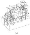
- toy apparatus for joining two sheets of paper or the like is designed to resemble in appearance a conventional sewing machine.
- the apparatus has a hollow base 10 and a hollow head 12 supported by a column 14 at one end of the base.
- the head extends over the base 10 to define an opening to receive the sheets of paper.
- the upper face 16 of the base 10 forms a flat table on which the sheets of paper can be supported.
- the apparatus has a vertically reciprocating cutter 20 which co-operates with a plate 22, set into the face 16 of base 10, to cut two flaps and apertures in the sheets of paper, as described below, a tucking mechanism 24 for folding and tucking the flaps through one of the apertures, a feed mechanism 74 for feeding the sheets of paper over the table, and a drive mechanism operated by a handle 119 for driving the cutter, tucking and feeding mechanisms.
- the cutter 20 comprises a bar of steel or other suitable material, of rectangular cross-section and slidable vertically in guides formed in the head 12. At its lower end the cutter is divided by a vertical slot 28 into two cutting elements 30 and 32. The cutting elements project, in the lowermost position of the cutter, into respective rectangular apertures 40 and 42 in the plate 22.
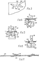
- Cutting element 30 is shaped to provide inclined cutting edges 31 which co-operate with the edges of aperture 40 to cut through sheets of paper along three sides 110 of a rectangle, leaving one shorter side ll2 uncut, so as to form a flap 114 in each sheet ( Figure 3).
- the other cutting element 32 is similarly shaped to provide inclined cutting edges 33 which co-operate with the edges of aperture 42 to cut the sheets of paper along three sides 115 of a rectangle, leaving the shorter side 116 uncut to form flaps 118.
- the uncut sides 112 and 116 of the two rectangles are parallel to and separated by a short distance from one another as shown in Figure 3.
- the flaps are of the same width, but flaps 114 are longer than flaps 118.
- the cutting element 30 is also shaped to push the flaps 114 downwards through the aperture 40 so that the free ends of the flaps 114 are below the plate 22. This ensures that, as the sheets of paper are moved stepwise as described below, the flaps 114 are caught by the edge of the aperture 40 in plate 22 and are folded back by movement of the sheets.
- Reciprocation of the cutter 20 is effected by means of rod 50 one end of which projects into an eye 21 in the cutter.
- the rod 50 is fulcrumed at an intermediate point on a shaft 52 fixed in the head 12 and its other end is connected to an eccentric 54 fixed to a shaft 56 rotatable by the handle 28.
- the rod 50 slides horizontally on shaft 56, so that rotation of the eccentric 54 produces only vertical reciprocation of the cutter.
- the tucking mechanism 24 comprises a pin 60 which reciprocates vertically between an upper position in which it projects through a hole 62 in the plate 22 and a lower position in which it is withdrawn into the hole.
- the pin 60 slides in a boss 64 formed in the underside of plate 22 which maintains the vertical orientation of the pin.
- the pin 60 is carried by a rectangular frame 66 mounted so as to be vertically reciprocable.
- a rod 68 mounted eccentrically with respect to a drive shaft 70, engages the frame 66, so as to effect vertical reciprocation of the frame as the drive shaft rotates.
- the rod 68 extends between, and is carried by, two rotatable members 74 fixed to the drive shaft 70.
- the member 74 has a radially outer face 76 whose surface is part of a cylinder of revolution coaxial with the drive shaft 70. The radius of this part cylindrical face is such that, when the frame is at the uppermost position of its travel, it projects slightly above the surface of the plate 22.
- two slots 78 are formed in the plate 22, one on each side of the path of travel of the cutter 20.
- the members 74 act to feed the paper sheets stepwise over the plate 22, and the arcuate length of each face 76 is therefore made equal to the desired increment of movement of the paper sheets during each cutting cycle.
- the faces 76 may be provided with a gripping surface, e.g. of rubber.
- a roller 80 Positioned above each slot 78 is a roller 80, freely rotatable about a horizontal axis. The radius of each roller is such that sheets of paper are gripped between the roller and the face 76 of the corresponding feed member 74 to feed the sheets at the appropriate part of the cycle.
- the drive shaft 70 is driven from shaft 56 by means of a vertical shaft 82 extending through the column 14.
- the vertical shaft 82 is coupled to shafts 56 and 70 by pairs of bevel gears 84,85 and 86,87. This provides a positive drive ensuring that the movements of the pin 60 and feed members 74 are correctly synchronised with movements of the cutter 20.
- the lower part of the cutter 20 and the rollers 80 are surrounded by a skirt 90 which extends downwards from the head 12.
- the lower edge 91 of the skirt 90 is spaced a short distance from the table 22, to leave a gap sufficient to receive the sheets of paper or the like.
- the skirt 90 acts as a guard to prevent a child's fingers from reaching the sharp edges of the cutter.
- the toy may be provided with a decorative element 96 shaped to resemble a cotton reel and mounted rotatably on top of the head 12, the element being rotated by engagement of a bevel gear 97 with the bevel gear 84 on drive shaft 56.
- An arm 97 may also be provided, to resemble the thread tensioning device of a sewing machine, the arm 97 being fixed to the cutter 20 and projecting outwards through a vertical slot in the head 12.
- the upward movement of the pin 60 is arranged so that the pin emerges from the hole 62 as the feed members 74 move out of engagement with the sheets.
- the flaps 118 are above the hole 62, so that upward movement of the pin 60 pushes the flaps 114 upwards, through the aligned apertures in the sheets left by the flaps 118 as the latter flaps are also pushed upwards.
- the flaps 114 are thus tucked through the aligned apertures, locking the two sheets together at that point.
- the pin 60 is then moved downwards, and at the same time the cutter 20 begins its next downwards cutting stroke.
- the cycle is repeated, so that the sheets are joined together at successive locations as the sheets are fed through the apparatus. By suitably guiding the sheets as they are fed through, they can be joined along a straight or slightly curved line.
- the length of the flaps l14 is such that the flaps 114 project over the uncut edge 115 of the aperture left by the flaps 118, as shown in Figure 11, so that the sheets of paper are effectively locked together by the flaps 114.
- the apertures 40 and 42 in the plate 182 have a width of 4.10 mm, the aperture 40 having a length of 7.15 mm and the aperture 42 a length of 2.75 mm, the apertures being separated by a distance of 2.35 mm. It will be appreciated however that other dimensions could be used.
Landscapes
- Engineering & Computer Science (AREA)
- Textile Engineering (AREA)
- Mechanical Engineering (AREA)
- Treatment Of Fiber Materials (AREA)
- Toys (AREA)
Applications Claiming Priority (2)
| Application Number | Priority Date | Filing Date | Title |
|---|---|---|---|
| GB8300432 | 1983-01-07 | ||
| GB838300432A GB8300432D0 (en) | 1983-01-07 | 1983-01-07 | Joining sheets of paper & c |
Publications (1)
| Publication Number | Publication Date |
|---|---|
| EP0117601A1 true EP0117601A1 (fr) | 1984-09-05 |
Family
ID=10536055
Family Applications (1)
| Application Number | Title | Priority Date | Filing Date |
|---|---|---|---|
| EP84300081A Withdrawn EP0117601A1 (fr) | 1983-01-07 | 1984-01-06 | Appareil pour réunir des feuilles de papier |
Country Status (2)
| Country | Link |
|---|---|
| EP (1) | EP0117601A1 (fr) |
| GB (1) | GB8300432D0 (fr) |
Cited By (2)
| Publication number | Priority date | Publication date | Assignee | Title |
|---|---|---|---|---|
| GB2255305A (en) * | 1991-04-11 | 1992-11-04 | Heidelberger Druckmasch Ag | Assuring orderly web travel in a folder |
| US5186444A (en) * | 1991-04-11 | 1993-02-16 | Heidelberg Harris Gmbh | Method and device for assuring orderly web travel in a folder by punching holes in a paper width direction |
Citations (6)
| Publication number | Priority date | Publication date | Assignee | Title |
|---|---|---|---|---|
| FR33831E (fr) * | 1927-05-09 | 1929-03-25 | Dispositif de fixation, sur les corps plastiques ou rendus plastiques, des montures d'objets de toilette, de mode, etc. | |
| GB604018A (en) * | 1945-02-07 | 1948-06-28 | Singer Mfg Co | Electrostatic bonding machine |
| DE811309C (de) * | 1949-01-01 | 1951-08-20 | Claus Koenig | Verfahren und Einrichtung zum Einfassen der Kanten von Zeichnungen |
| GB792852A (en) * | 1956-04-03 | 1958-04-02 | Howard J Jewell | Paper fastening device |
| DE1273483B (de) * | 1966-07-12 | 1968-07-25 | Hans Biel Fa | Verfahren und Vorrichtung zum Heften mehrerer uebereinandergelegter Schreib- und Durchschreibpapierbahnen |
| FR2097907A5 (fr) * | 1970-06-18 | 1972-03-03 | Goebel Maschinen Gmbh |
-
1983
- 1983-01-07 GB GB838300432A patent/GB8300432D0/en active Pending
-
1984
- 1984-01-06 EP EP84300081A patent/EP0117601A1/fr not_active Withdrawn
Patent Citations (6)
| Publication number | Priority date | Publication date | Assignee | Title |
|---|---|---|---|---|
| FR33831E (fr) * | 1927-05-09 | 1929-03-25 | Dispositif de fixation, sur les corps plastiques ou rendus plastiques, des montures d'objets de toilette, de mode, etc. | |
| GB604018A (en) * | 1945-02-07 | 1948-06-28 | Singer Mfg Co | Electrostatic bonding machine |
| DE811309C (de) * | 1949-01-01 | 1951-08-20 | Claus Koenig | Verfahren und Einrichtung zum Einfassen der Kanten von Zeichnungen |
| GB792852A (en) * | 1956-04-03 | 1958-04-02 | Howard J Jewell | Paper fastening device |
| DE1273483B (de) * | 1966-07-12 | 1968-07-25 | Hans Biel Fa | Verfahren und Vorrichtung zum Heften mehrerer uebereinandergelegter Schreib- und Durchschreibpapierbahnen |
| FR2097907A5 (fr) * | 1970-06-18 | 1972-03-03 | Goebel Maschinen Gmbh |
Cited By (3)
| Publication number | Priority date | Publication date | Assignee | Title |
|---|---|---|---|---|
| GB2255305A (en) * | 1991-04-11 | 1992-11-04 | Heidelberger Druckmasch Ag | Assuring orderly web travel in a folder |
| US5186444A (en) * | 1991-04-11 | 1993-02-16 | Heidelberg Harris Gmbh | Method and device for assuring orderly web travel in a folder by punching holes in a paper width direction |
| GB2255305B (en) * | 1991-04-11 | 1994-09-07 | Heidelberger Druckmasch Ag | Method and device for assuring orderly web travel in a folding device |
Also Published As
| Publication number | Publication date |
|---|---|
| GB8300432D0 (en) | 1983-02-09 |
Similar Documents
| Publication | Publication Date | Title |
|---|---|---|
| DE1485265C2 (de) | Fadenschneideinrichtung an Nähmaschinen | |
| EP0245214A1 (fr) | Machine à coudre les objets rigides, en cuir par exemple | |
| DE2338473C2 (de) | Fadenabschneider für eine Doppelsteppstichnähmaschine | |
| CN111020903B (zh) | 起缝剪线机构及其方法 | |
| CN221608342U (zh) | 一种单驱动少鸟巢剪线机构及缝纫机 | |
| CN101144229A (zh) | 缝纫机 | |
| EP0117601A1 (fr) | Appareil pour réunir des feuilles de papier | |
| US4359008A (en) | Apparatus for providing a zipper closable garment pocket entry | |
| DE3856244T2 (de) | Verfahren zum kontinuierlichen Transport von Werkstücken durch eine Reihe von Arbeitsstationen | |
| US2845885A (en) | Sewing machine for burlap bags | |
| US3383107A (en) | Device for withdrawing sewn material from sewing machines | |
| JP2929343B2 (ja) | ズボン用前立片の縁縫い加工方法 | |
| DE69105683T2 (de) | Überwendlichnähmaschine für Hosenschlitzstreifen. | |
| US3481292A (en) | Hemming device | |
| DE3600323C2 (de) | Querschneidvorrichtung für Materialbahnen | |
| US3425377A (en) | Sewing machine | |
| DD276111A5 (de) | Vorrichtung zur herstellung eines ueberwendlichstichtyps | |
| EP1426150A1 (fr) | Dispositif de traitement d'une surface a broder | |
| JPH11267382A (ja) | 縫製品を裁断する、ミシンのための付加装置 | |
| DE2640557B1 (de) | Fadentrennvorrichtung an naehmaschinen zum durchtrennen der fadenkette | |
| US3886878A (en) | Automatic fabric handling apparatus | |
| CN213013353U (zh) | 一种扒缝机构及具有该扒缝机构的扒缝机 | |
| US3149595A (en) | Thread chain severing means for book sewing machines | |
| JPS5825990Y2 (ja) | 自動縫製装置 | |
| EP0034921A2 (fr) | Machine et procédé pour fabrication de cahiers brochés au dos |
Legal Events
| Date | Code | Title | Description |
|---|---|---|---|
| PUAI | Public reference made under article 153(3) epc to a published international application that has entered the european phase |
Free format text: ORIGINAL CODE: 0009012 |
|
| AK | Designated contracting states |
Designated state(s): BE DE FR GB IT NL |
|
| STAA | Information on the status of an ep patent application or granted ep patent |
Free format text: STATUS: THE APPLICATION IS DEEMED TO BE WITHDRAWN |
|
| 18D | Application deemed to be withdrawn |
Effective date: 19850506 |
|
| RIN1 | Information on inventor provided before grant (corrected) |
Inventor name: ROUSE, ROBERT |