EP0117614A2 - Graphische Anzeigeeinheit für numerisch gesteuerte Maschinen - Google Patents
Graphische Anzeigeeinheit für numerisch gesteuerte Maschinen Download PDFInfo
- Publication number
- EP0117614A2 EP0117614A2 EP84300377A EP84300377A EP0117614A2 EP 0117614 A2 EP0117614 A2 EP 0117614A2 EP 84300377 A EP84300377 A EP 84300377A EP 84300377 A EP84300377 A EP 84300377A EP 0117614 A2 EP0117614 A2 EP 0117614A2
- Authority
- EP
- European Patent Office
- Prior art keywords
- profile
- picture
- memory means
- rams
- graphic
- Prior art date
- Legal status (The legal status is an assumption and is not a legal conclusion. Google has not performed a legal analysis and makes no representation as to the accuracy of the status listed.)
- Withdrawn
Links
Images


Classifications
-
- G—PHYSICS
- G05—CONTROLLING; REGULATING
- G05B—CONTROL OR REGULATING SYSTEMS IN GENERAL; FUNCTIONAL ELEMENTS OF SUCH SYSTEMS; MONITORING OR TESTING ARRANGEMENTS FOR SUCH SYSTEMS OR ELEMENTS
- G05B19/00—Program-control systems
- G05B19/02—Program-control systems electric
- G05B19/18—Numerical control [NC], i.e. automatically operating machines, in particular machine tools, e.g. in a manufacturing environment, so as to execute positioning, movement or co-ordinated operations by means of program data in numerical form
- G05B19/406—Numerical control [NC], i.e. automatically operating machines, in particular machine tools, e.g. in a manufacturing environment, so as to execute positioning, movement or co-ordinated operations by means of program data in numerical form characterised by monitoring or safety
- G05B19/4069—Simulating machining process on screen
-
- G—PHYSICS
- G05—CONTROLLING; REGULATING
- G05B—CONTROL OR REGULATING SYSTEMS IN GENERAL; FUNCTIONAL ELEMENTS OF SUCH SYSTEMS; MONITORING OR TESTING ARRANGEMENTS FOR SUCH SYSTEMS OR ELEMENTS
- G05B2219/00—Program-control systems
- G05B2219/30—Nc systems
- G05B2219/35—Nc in input of data, input till input file format
- G05B2219/35287—Verify, check program by drawing, display part, testpiece
-
- G—PHYSICS
- G05—CONTROLLING; REGULATING
- G05B—CONTROL OR REGULATING SYSTEMS IN GENERAL; FUNCTIONAL ELEMENTS OF SUCH SYSTEMS; MONITORING OR TESTING ARRANGEMENTS FOR SUCH SYSTEMS OR ELEMENTS
- G05B2219/00—Program-control systems
- G05B2219/30—Nc systems
- G05B2219/35—Nc in input of data, input till input file format
- G05B2219/35341—Display finishing, finishing margin, work, tool and chuck shape, different colours
-
- G—PHYSICS
- G05—CONTROLLING; REGULATING
- G05B—CONTROL OR REGULATING SYSTEMS IN GENERAL; FUNCTIONAL ELEMENTS OF SUCH SYSTEMS; MONITORING OR TESTING ARRANGEMENTS FOR SUCH SYSTEMS OR ELEMENTS
- G05B2219/00—Program-control systems
- G05B2219/30—Nc systems
- G05B2219/35—Nc in input of data, input till input file format
- G05B2219/35501—Colour display
-
- G—PHYSICS
- G05—CONTROLLING; REGULATING
- G05B—CONTROL OR REGULATING SYSTEMS IN GENERAL; FUNCTIONAL ELEMENTS OF SUCH SYSTEMS; MONITORING OR TESTING ARRANGEMENTS FOR SUCH SYSTEMS OR ELEMENTS
- G05B2219/00—Program-control systems
- G05B2219/30—Nc systems
- G05B2219/36—Nc in input of data, input key till input tape
- G05B2219/36073—Display original and modified part in different colour, highlight, shading, filling
Definitions
- the present invention relates to a graphic display unit for numerical controllers.
- a numerical controller provided with a graphic display unit which displays, in addition to the profiles or shapes of a blank, a tool and a chuck, a finished shape and the shape of a finishing allowance through utilization of the loci of the tool obtained by a provisional execution of an NC machining program.
- a check on the NC machining program has been made far easier than in the past.
- the finished shape, the shape of the finishing allowance, the blank profile, the tool profile and the chuck shape are all displayed with contour lines, and the regions of areas surrounded by the contour lines are all displayed in the same color (ground color). Therefore, the proposed display units have the defect that a clear recognition of each part is unexpectedly difficult in a visual inspection of the NC machining program on the display screen, introducing the possibility of a misjudgement on the validity of the program.
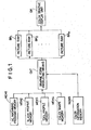
- a graphic display unit for numerical controllers comprising:
- an NC machining program data on the blank profile, data on the tool profile, data on the chuck shape and information on colors for the respective profiles are stored in an NC machining program memory MEM1, a blank profile memory MEM2, a tool profile memory MEM3, a chuck shape memory MEM4 and a color information memory MEM5, respectively.
- graphic form producing means CNT painted-out graphic forms of a finished shape, a.finishing allowance profile, the blank profile, the chuck shape and the tool profile, which are produced on the basis of the stored information of the memories MEM1, MEM2, MEM3 and MEM4 are written into those of a plurality of picture RAMs BR 1 to BR n which are specified by the color information
- a color graphic display DP receives the outputs of the plurality of picture RAMs and displays a graphic form in a color or colors defined by a combination of the picture RAMs.
- reference numeral 1 indicates a microcomputer; 2 and 3 designate its data and address buses; 4R identifies a red picture RAM; 4G denotes a green picture RAM; 4B represents a blue picture RAM; 5 shows a work RAM, 6 and 7 refer to parallel-serial converters; 8 signifies a CRT controller; 9 signifies a flip-flop; 10 indicates a serial-parallel converter; 11 designates an address decoder; 12 identifies a picture specifying information latch circuit; 13 denotes a vertical synchronizing signal synchronizer; 14 to 19 and 21 represent input switching circuits; 20 shows an OR circuit; 22 refers to a data driver; 23R, 23G and 23B signify latch circuits; 24 indicates a color graphic display; 25 designates a RAM write pulse generator; 26 identifies a gate circuit; 30 denotes a color information file memory; 31 represents a CMOS memory; 32 shows a blank file memory; and 33 refers to a tool file memory.
- the red, green and blue picture RAMs 4R, 4G are and 4B/read/write memories for storing graphic forms to be displayed, and each have storage areas corresponding to dots of a displayed picture.
- an area stored only in the red picture RAM 4B is displayed in red
- an area stored only in the green or blue picture RAM 4G or 4B is displayed in green or blue.
- An area written in two or more picture RAMs is displayed in a mixed color.
- the work RAM 5 is a write/read memory which is used for a paint-out work described later, and has storage areas corresponding to the storage areas of the picture RAMs 4R, 4G and 4B.
- These picture RAMs 4R, 4G and 4B are accessible by the microcomputer 1 to write therein information at desired addresses or to read out therefrom the stored information. Further, their entire areas are sequentially and synchronously accessed by scanning addresses of the CRT controller 8 and the contents of the picture RAMs 4R, 4G and 4B are repeatedly output to the parallel-serial converters 6 and 7 with a fixed period. The output of the serial-parallel converter 10 is provided to the inputs of the picture RAMs 4R, 4G and 4B, and these RAMs are rewritten by this input, too.
- the picture specifying information latch circuit 12 specifies the picture RAM which is rewritten by the output of the serial-parallel converter 10.
- the picture specifying information latch circuit 12 includes latch circuits 23R, 23G and 23B which are used for specifying the red, green and blue picture RAMs 4R, 4G and 4B, respectively.
- the outputs of the latch circuits 23R, 23G and 23B are provided to chip select terminals C S of the picture RAMs 4R, 4G and 4B after being synchronized by the vertical synchronizing signal synchronizer 13 which is supplied with a vertical synchronizing signal from the CRT controller 8.
- the parallel bit outputs of the picture RAMs 4R, 4G and 4B, provided to the parallel-serial converter 6, and the parallel bit output of the work RAM 5, provided to the parallel-serial converter 7, are both converted into serial bit outputs.
- the output of the parallel-serial converter 6 is applied to a set input terminal of the flip-flop 9, whereas the output of the parallel-serial converter 7 is provided to a reset terminal of the flip-flop 9.
- the flip-flop 9 is reset by a horizontal synchronizing signal applied thereto via the OR circuit 20 from the CRT controller 8 as well.
- the output of.the flip-flop 9 is converted by the serial-parallel converter 10 into a parallel bit output, which is fed back to the inputs of the picture RAMs 4R, 4G and 4B, as described previously.
- the color graphic display 24 receives the output of the parallel-serial converter 6 as red, green and blue video signals, and displays, on its screen, a graphic form in a color depending upon a combination of the abovesaid color video signals.
- the parallel-serial converter 6 is shown in the form of one block for convenience of illustration but, in practice, it includes parallel-serial converters equal in number to the colors used, i. e. red, green and blue, and they are arranged so that their outputs are switched between the color graphic display 24 and the flip-flop 9. It is also possible, of course, to provide a parallel-serial converter for the paint-out work, separately of the parallel-serial converters for display use.
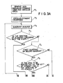
- Fig. 3 is a flowchart showing an example of software for implementing the graphic form producing function of a color graphic display unit of the present invention.
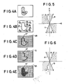
- a graphic form of such a shape as shown in Fig. 4A it is necessary to write a "1" in the area of the red picture RA M 4R which corresponds to it is the plane figure of the graphic form/desired to display.
- a description will be given first, of the graphic form producing function of the unit of this embodiment in connection with the abovesaid case.
- step P2 Graphic data on the contour of the plane figure is separately produced or input, and the microcomputer 1 approximates all the graphic data by straight lines through using known circular-straight conversion or like techniques.
- step P3 the contour of the graphic form shown in Fig. 4A is divided into segments l 1 to l 10 as shown in Fig. 4B.
- step P3 the contour of the graphic form thus approximated by the straight lines is written into the red picture RAM 4R and, in order to write in the work RAM 5 the terminating point of the graphic form painting-cut work, the quadrant in which each straight line lies is checked using the starting point of the straight line (step P3). This can be achieved by checking the signs of the coordinate values of the starting and terminating points of the straight line.
- step P4 to P9 the microcomputer 1 performs the following processing (steps P4 to P9): .
- step P7 when the direction of travel of the straight lines is determined to be clockwise, the areas on the right of them are painted out; then the straight lines l 1 , L 2 and l 10 are decided as lying in the first or second quadrant, and the straight lines l 3 to l 9 are decided as lying in the third or fourth quadrant.
- the contour of the graphic form (l 1 to l 10 ) is written into the red picture RAM 4R as shown in Fig. 4C, and the positions of terminating points (l 3 to l 9 ) of the paint-out work are written in the work RAM 5 as shown in Fig. 4D.
- the arrows in Figs. 4C and D indicate the scanning direction.
- the microcomputer 1 specifies the picture RAM to be painted out, and starts the CRT controller 8 so as to carry out the paint-out work by hardware processing.
- the picture RAM specifying operation is accomplished by the picture specifying information latch circuit 12.
- the latch circuit 23R is set.
- the output of the red picture RAM 4R is provided via the parallel-serial converter 6 to the set terminal of the flip-flop 9 and the output of the work RAM 5 is provided via the parallel-serial converter 7 to the reset terminal of the flip-flop 9.
- Fig. 7 is a timing chart showing, by way of example, signal waveforms occurring at respective parts of the unit shown in Fig. 2 during the paint-out work by hardware processing.
- a read cycle is generated to read out the contents of the red picture RAM 4R and the work RAM 5 in synchronism with each other; the flip-flop 9 is set by a "1" signal in the converted serial output of the red picture RAM 4R; and the flip-flop 9 is reset by a "1" signal in the converted serial output of the work RAM 5.
- the output of the flip-flop 9 is converted by the serial-parallel converter 10 into parallel data and, in the latter stage of the scanning address, a write cycle is developed to rewrite the content of the red picture RAM 4R by the output of the serial-parallel converter 9. Since the red picture RAM 4R and the work RAM 5 have stored therein the contour of the graphic form and the terminating points of the paint-out work, respectively, as referred to previously, the flip-flop 9 specifies the area to be painted out. As a result of this, the red picture RAM 4R is rewritten as shown in Fig. 4E, providing a painted-out plane figure.
- the display unit is controlled by the microcomputer 1 not to provide a display and, after the paint-out work, it is turned into an ordinary display mode.
- the arrangement which resets the flip-flop 9 by the horizontal synchronizing signal is intended to facilitate the operation of painting out the entire area of the display screen.
- the color graphic display unit for numerical controllers provides a colored display through utilization of such a graphic form producing function as described above.
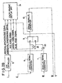
- Fig. 8 schematically shows an example of a displayed picture.
- Reference numeral 80 indicates a chuck, 81 a blank, 82 a finishing allowance, 83 a finished shape and 84 a tool. They are displayed in different colors. Further, the correspondence between the colors and the graphic forms is also displayed. For instance, in the case of coloring the tool 84 in red, the finished shape 83 in blue, the finishing allowance 82 in green, the blank 81 in yellow and the chuck 80 in purple, the plane figures of the tool 84, the blank 81 and the chuck 80, the plane figures of the finishing allowance 82 and the blank 81 and the plane figures of the finished shape 83 and the chuck 80 are written into the red, green and blue picture RAMs 4R, 4G and 4B, respectively. Of course, the graphic forms may also be displayed in colors different from those mentioned above.
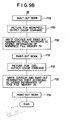
- Fig. 9 is a flowchart showing an example of the software arrangement for providing such a display as shown in Fig. 8.
- the microcomputer 1 When supplied with a colored display command, the microcomputer 1 reads out color information for the chuck from the color information file memory 30 and selects the picture RAM to be accessed, thereby specifying a color (step P20). Then, the microcomputer 1 reads out from the chuck shape file memory 31 data specifying the shape of the chuck and writes its contour and the terminating points of the paint-out work into the selected picture RAM and the work RAM (step P21).
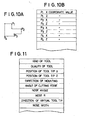
- the chuck shape file memory 31 for example, the coordinate values of respective points such as shown in Fig. 10A are prestored as shown in Fig. 10B. The contents of the chuck shape file memory 31 can be modified by the user.
- the microcomputer 1 Upon completion of the contour lines and the paint-out terminating points, the microcomputer 1 carries out the paint-out work by hardware processing, writing the plane figure of the chuck into the selected picture RAM (step P22).
- step P22 to P34 Similar operations are repeated (steps P22 to P34), by which the plane figures of the finished shape, the finishing allowance profile, the blank profile and the tool profile are respectively written into the picture RAMs 4R, 4G and 4B which are respectively specified by the color information stored in the color information file memory 30.
- the contour line of the finished shape is generated by interpreting a finishing part of the NC machining program stored in the CMOS memory 31, and the contour line of the finishing allowance is generated through using the interpreted results of a roughing part of the NC machining program.
- the contour line of the blank profile is obtained by reading out the contents of the blank file memory 32 which has stored therein data on the blank profile, the distances from its end face (the underside of the chuck) and so forth, along with the quality of the blank. These operations can be carried out by the same method as has been employed in the past. Further, the contour line of the tool profile is obtained by reading out the contents of the tool file memory 33, since the memory 33 has stored therein contents such, for example, as shown in Fig. 11 by which the profile of the tool can be specified. The contents of the tool file memory 33 can also be modified by the user.
- paint-out work of the plane figure is performed by hardware processing, this is intended to increase the processing speed and the paint-out work may also be carried out by software processing as usual.
- the finished shape, the finishing allowance, the blank profile, the tool profile and the chuck shape are displayed in the form of plane figures (painted-out graphic forms) and in different colors, these profiles are clear at a glance, permitting certain and easy checking of the validity of an NC machining program. Furthermore, even in the case of applying the present invention to an arrangement for displaying the cutting conditions while moving the tool along a machining route, its recognition becomes easier than in the case of displaying it by lines alone.
Landscapes
- Engineering & Computer Science (AREA)
- Human Computer Interaction (AREA)
- Manufacturing & Machinery (AREA)
- Physics & Mathematics (AREA)
- General Physics & Mathematics (AREA)
- Automation & Control Theory (AREA)
- Numerical Control (AREA)
- Controls And Circuits For Display Device (AREA)
- Image Generation (AREA)
Applications Claiming Priority (2)
| Application Number | Priority Date | Filing Date | Title |
|---|---|---|---|
| JP58014408A JPS59140513A (ja) | 1983-01-31 | 1983-01-31 | Nc用カラ−グラフイツク表示装置 |
| JP14408/83 | 1983-01-31 |
Publications (2)
| Publication Number | Publication Date |
|---|---|
| EP0117614A2 true EP0117614A2 (de) | 1984-09-05 |
| EP0117614A3 EP0117614A3 (de) | 1986-03-05 |
Family
ID=11860218
Family Applications (1)
| Application Number | Title | Priority Date | Filing Date |
|---|---|---|---|
| EP84300377A Withdrawn EP0117614A3 (de) | 1983-01-31 | 1984-01-23 | Graphische Anzeigeeinheit für numerisch gesteuerte Maschinen |
Country Status (2)
| Country | Link |
|---|---|
| EP (1) | EP0117614A3 (de) |
| JP (1) | JPS59140513A (de) |
Cited By (15)
| Publication number | Priority date | Publication date | Assignee | Title |
|---|---|---|---|---|
| EP0148339A3 (en) * | 1983-12-08 | 1985-08-14 | Dr. Johannes Heidenhain Gmbh | Circuitry for graphical display using a microprocessor |
| GB2163926A (en) * | 1984-08-31 | 1986-03-05 | Gen Electric | Color enhanced display for a numerical control system |
| GB2163927A (en) * | 1984-08-31 | 1986-03-05 | Gen Electric | Graphic display for a numerical control system |
| EP0145934A3 (en) * | 1983-11-07 | 1987-01-28 | Mitsubishi Denki Kabushiki Kaisha | Tool display method and device for machining apparatus equipped with numerical control unit |
| DE3706291A1 (de) * | 1986-02-27 | 1987-09-03 | Mitsubishi Electric Corp | Arbeitsprogrammpruefvorrichtung |
| DE3933494A1 (de) * | 1988-10-07 | 1990-04-12 | Mitsubishi Electric Corp | Verfahren zur anzeige einer darstellung auf einer kathodenstrahlroehre eines numerischen steuersystems |
| EP0372107A1 (de) * | 1988-12-06 | 1990-06-13 | Dr. Johannes Heidenhain GmbH | Verfahren zur Simulation der Bearbeitung eines Werkstückes und Darstellung desselben, sowie Vorrichtung zur Durchführung des Verfahrens |
| US5295075A (en) * | 1990-09-25 | 1994-03-15 | Johannes Heidenhain Gmbh | Method and apparatus for machining workpieces with numerically controlled machines |
| US5353232A (en) * | 1990-09-25 | 1994-10-04 | Dr. Johannes Heidenhain Gmbh | Method and apparatus for ascertaining tool path contours in numerically controlled machines |
| EP0578828A4 (de) * | 1992-01-28 | 1995-02-15 | Fanuc Ltd | Bildschirmanzeigeverfahren für numerische steuerung. |
| EP0578831A4 (de) * | 1992-02-03 | 1995-02-15 | Fanuc Ltd | Vorrichtung zur graphische überwachung von kollison. |
| US5434793A (en) * | 1990-09-25 | 1995-07-18 | Johannes Heidenhain Gmbh | Method and apparatus for ascertaining tool path contours approximating curved contour intersection lines in numerically controlled machines |
| FR2797410A1 (fr) * | 1999-05-11 | 2001-02-16 | Falcon Machine Tools Co Ltd | Systeme interactif entre une machine-outil et un operateur |
| EP1260889A1 (de) * | 1997-02-26 | 2002-11-27 | AMADA COMPANY, Ltd. | Verfahren zur Bestimmung der Biegereihenfolge in einer Werkzeugmaschine |
| DE19883015B4 (de) * | 1998-08-28 | 2009-07-30 | Mitsubishi Denki K.K. | Drahtentladungs-Bearbeitungsverfahren und Drahtentladungs-Bearbeitungsvorrichtung |
Families Citing this family (6)
| Publication number | Priority date | Publication date | Assignee | Title |
|---|---|---|---|---|
| JPS61184610A (ja) * | 1985-02-12 | 1986-08-18 | Fanuc Ltd | 移動軌跡描画方式 |
| JPS6312207U (de) * | 1986-07-08 | 1988-01-27 | ||
| JPS63167905A (ja) * | 1986-12-30 | 1988-07-12 | Fanuc Ltd | 加工図描画方法 |
| JPS6428706A (en) * | 1987-07-24 | 1989-01-31 | Fanuc Ltd | Interactive programming device |
| JPH01140304A (ja) * | 1987-11-27 | 1989-06-01 | Fanuc Ltd | 対話型nc入力装置 |
| JP2663931B2 (ja) * | 1995-11-27 | 1997-10-15 | 三菱電機株式会社 | 数値制御装置の図形表示方法 |
-
1983
- 1983-01-31 JP JP58014408A patent/JPS59140513A/ja active Granted
-
1984
- 1984-01-23 EP EP84300377A patent/EP0117614A3/de not_active Withdrawn
Cited By (16)
| Publication number | Priority date | Publication date | Assignee | Title |
|---|---|---|---|---|
| EP0145934A3 (en) * | 1983-11-07 | 1987-01-28 | Mitsubishi Denki Kabushiki Kaisha | Tool display method and device for machining apparatus equipped with numerical control unit |
| EP0148339A3 (en) * | 1983-12-08 | 1985-08-14 | Dr. Johannes Heidenhain Gmbh | Circuitry for graphical display using a microprocessor |
| GB2163926A (en) * | 1984-08-31 | 1986-03-05 | Gen Electric | Color enhanced display for a numerical control system |
| GB2163927A (en) * | 1984-08-31 | 1986-03-05 | Gen Electric | Graphic display for a numerical control system |
| DE3706291A1 (de) * | 1986-02-27 | 1987-09-03 | Mitsubishi Electric Corp | Arbeitsprogrammpruefvorrichtung |
| DE3933494A1 (de) * | 1988-10-07 | 1990-04-12 | Mitsubishi Electric Corp | Verfahren zur anzeige einer darstellung auf einer kathodenstrahlroehre eines numerischen steuersystems |
| EP0372107A1 (de) * | 1988-12-06 | 1990-06-13 | Dr. Johannes Heidenhain GmbH | Verfahren zur Simulation der Bearbeitung eines Werkstückes und Darstellung desselben, sowie Vorrichtung zur Durchführung des Verfahrens |
| US5353232A (en) * | 1990-09-25 | 1994-10-04 | Dr. Johannes Heidenhain Gmbh | Method and apparatus for ascertaining tool path contours in numerically controlled machines |
| US5295075A (en) * | 1990-09-25 | 1994-03-15 | Johannes Heidenhain Gmbh | Method and apparatus for machining workpieces with numerically controlled machines |
| US5434793A (en) * | 1990-09-25 | 1995-07-18 | Johannes Heidenhain Gmbh | Method and apparatus for ascertaining tool path contours approximating curved contour intersection lines in numerically controlled machines |
| EP0578828A4 (de) * | 1992-01-28 | 1995-02-15 | Fanuc Ltd | Bildschirmanzeigeverfahren für numerische steuerung. |
| EP0578831A4 (de) * | 1992-02-03 | 1995-02-15 | Fanuc Ltd | Vorrichtung zur graphische überwachung von kollison. |
| EP1260889A1 (de) * | 1997-02-26 | 2002-11-27 | AMADA COMPANY, Ltd. | Verfahren zur Bestimmung der Biegereihenfolge in einer Werkzeugmaschine |
| US6795095B2 (en) | 1997-02-26 | 2004-09-21 | Amada Company Limited | Method for determining bending order and disposition of dies |
| DE19883015B4 (de) * | 1998-08-28 | 2009-07-30 | Mitsubishi Denki K.K. | Drahtentladungs-Bearbeitungsverfahren und Drahtentladungs-Bearbeitungsvorrichtung |
| FR2797410A1 (fr) * | 1999-05-11 | 2001-02-16 | Falcon Machine Tools Co Ltd | Systeme interactif entre une machine-outil et un operateur |
Also Published As
| Publication number | Publication date |
|---|---|
| JPS59140513A (ja) | 1984-08-11 |
| EP0117614A3 (de) | 1986-03-05 |
| JPH0458042B2 (de) | 1992-09-16 |
Similar Documents
| Publication | Publication Date | Title |
|---|---|---|
| EP0117614A2 (de) | Graphische Anzeigeeinheit für numerisch gesteuerte Maschinen | |
| US4646228A (en) | Graphic display device | |
| US4992780A (en) | Method and apparatus for storing a two-dimensional image representing a three-dimensional scene | |
| JPS62192878A (ja) | 多角形の塗りつぶし方法 | |
| EP0106601B1 (de) | Farbanzeigeeinheit | |
| EP0083836A2 (de) | Verfahren und Gerät zur Anzeige der Bewegungsbahn in numerisch gesteuerten Maschinen | |
| JPH0514312B2 (de) | ||
| JPS59146309A (ja) | Nc用カラ−グラフイツク表示装置 | |
| JPH0570834B2 (de) | ||
| JPS59160181A (ja) | Nc用カラ−グラフイツク表示装置 | |
| JPH0311151B2 (de) | ||
| JP3534948B2 (ja) | 画像表示制御装置 | |
| JPS61131853A (ja) | 加工機用デイスプレイ方法及び装置 | |
| JPS5972514A (ja) | カラ−デイスプレイ装置を備えた数値制御装置 | |
| US5621433A (en) | Low-cost multichannel oscilliscope for teaching and demonstration purposes | |
| EP0151184B1 (de) | Vorrichtung zum betonen und anzeigen eines auf einer bestimmten adresseaufgespeicherten programmteiles einer numerischen steuerung | |
| JPS5969791A (ja) | カラ−グラフイツクデイスプレイ装置 | |
| JP3225416B2 (ja) | 画像処理装置 | |
| JPH0421207B2 (de) | ||
| JPS62222305A (ja) | 数値制御装置における画像表示方式 | |
| JPS61157908A (ja) | デイスプレイ付数値制御装置の干渉チエツク回路 | |
| JP3223393B2 (ja) | 画像処理装置 | |
| JPH05341832A (ja) | Cncの図形干渉チェック方式 | |
| DE3543252A1 (de) | Vorrichtung und verfahren zur anzeigesteuerung | |
| SU1522273A1 (ru) | Устройство дл отображени полутонового изображени на экране телевизионного приемника |
Legal Events
| Date | Code | Title | Description |
|---|---|---|---|
| PUAI | Public reference made under article 153(3) epc to a published international application that has entered the european phase |
Free format text: ORIGINAL CODE: 0009012 |
|
| AK | Designated contracting states |
Designated state(s): DE FR GB |
|
| PUAL | Search report despatched |
Free format text: ORIGINAL CODE: 0009013 |
|
| AK | Designated contracting states |
Kind code of ref document: A3 Designated state(s): DE FR GB |
|
| 17P | Request for examination filed |
Effective date: 19860725 |
|
| 17Q | First examination report despatched |
Effective date: 19880607 |
|
| STAA | Information on the status of an ep patent application or granted ep patent |
Free format text: STATUS: THE APPLICATION IS DEEMED TO BE WITHDRAWN |
|
| 18D | Application deemed to be withdrawn |
Effective date: 19881018 |
|
| RIN1 | Information on inventor provided before grant (corrected) |
Inventor name: TORIYAMA, SHUJI Inventor name: INOUE, TSUYOSHI Inventor name: NAGAMINE, TSUYOSHI |