EP0117729A2 - Dispositif et procédé de commande par ordinateur du balayage du faisceau électronique dans un appareil de tomographie utilisant les ions pour l'amélioration de la focalisation - Google Patents
Dispositif et procédé de commande par ordinateur du balayage du faisceau électronique dans un appareil de tomographie utilisant les ions pour l'amélioration de la focalisation Download PDFInfo
- Publication number
- EP0117729A2 EP0117729A2 EP84301181A EP84301181A EP0117729A2 EP 0117729 A2 EP0117729 A2 EP 0117729A2 EP 84301181 A EP84301181 A EP 84301181A EP 84301181 A EP84301181 A EP 84301181A EP 0117729 A2 EP0117729 A2 EP 0117729A2
- Authority
- EP
- European Patent Office
- Prior art keywords
- chamber
- target
- producing
- converging
- gas
- Prior art date
- Legal status (The legal status is an assumption and is not a legal conclusion. Google has not performed a legal analysis and makes no representation as to the accuracy of the status listed.)
- Withdrawn
Links
Images




Classifications
-
- H—ELECTRICITY
- H01—ELECTRIC ELEMENTS
- H01J—ELECTRIC DISCHARGE TUBES OR DISCHARGE LAMPS
- H01J35/00—X-ray tubes
-
- H—ELECTRICITY
- H01—ELECTRIC ELEMENTS
- H01J—ELECTRIC DISCHARGE TUBES OR DISCHARGE LAMPS
- H01J35/00—X-ray tubes
- H01J35/02—Details
- H01J35/14—Arrangements for concentrating, focusing, or directing the cathode ray
- H01J35/147—Spot size control
Definitions
- the present invention is directed to various modes of controlling the scanning electron beam, which produces X-rays in a computed tomography X-ray transmission scanner and more particularly to a control technique which takes advantage of the ionization by the beam of the ambient gas in the scan tube which, in turn, results in the production of positive ions for neutralizing the space charge of the electron beam and causes it to become self focusing.
- the invention also overcomes the problem of target degassing in this type of scanner.
- the beam expands from its point of origin, because of the mutual electrostatic repulsion of the electrons in the beam.
- the beam passes through a magnetic lens (solenoid) and a dipole deflecting magnet which scans the beam along a tungsten target located at the far end of a conical vacuum chamber.
- the solenoid serves to focus the beam to a small spot on the target.
- the self forces of the beam are dominated by its space charge, i.e. the electrons mutually repel each other. This repulsion limits the minimum beam spot size, which in the case of unit beam optical magnification, and cylindrical symmetry with respect to the beam axis can be no smaller'than the size of the initial beam waist at the electron gun.
- the electron beam optics of the scanner must be arranged in such a way that the beam expands from the electron gun to the solenoid lens and converges from the lens to a small spot on the target.
- the deflecting dipole magnet just downstream from the solenoid also acts as a converging lens, other configurations might be possible.
- the effective focal length of the dipole defines a minimum rate of divergence for the beam at the solenoid/dipole position, if the beam is to be focused at the target.
- the final beam spot size varies approximately inversely as the beam size at the solenoid/dipole. Therefore the beam should be large at this point, again implying the necessity of a diverging beam from the gun.
- the electron beam from the gun is self-diverging because of the repulsion due to its own charge. If the same conditions apply in the second section of the scan tube, the size of the beam spot at the target is then determined by the space charge of the beam.
- the speed of the vacuum pumps must be adequate to cope with the normal degassing of the chamber inner walls and with the considerable degassing of the target when struck by the high power electron beam. This mode of operation requires a vacuum pressure of less than 5 x 10 8 Torr and is the mode of operation originally envisioned by the system in the Boyd patent.
- I.A.F. ion aided focusing
- gas is deliberately introduced into the vacuum chamber.
- This type of scanner which will be described in more detail hereinafter, therefore, has some means of causing the beam to expand in the first section of the tube, from the gun to the lens, and employs a self-focused beam in the second section, from the lens to the target. Since it is neither possible nor desirable for the beam to be entirely self-focusing, an adjustable magnetic solenoid lens must still form part of the system in order to provide control of the focusing. The focusing is therefore referred to as "ion aided.” Some means of controlling the gas pressure is also required.
- a necessary'condition for the operation of the scanner is that the focusing of the electron beam be insensitive to ambient gas pressure fluctuations. It is also desirable that the radius of the beam spot at the target be as small as possible. This is achieved by selecting a gas pressure where the rate of decrease with pressure of electron beam spot size, due to ion aided focusing, is balanced by the rate of increase of spot size, due to multiple scattering in the ambient gas.
- a second aspect of stability is that the neutralization of the beam in the first half of the tube be very small so that the beam expands to the required dimension at the lens. At this gas pressure, this condition can only be satisfied by removing ions from the beam by means of ion collecting electrodes, as described in the previously recited Rand application.
- I.A.F. overcomes the problem of target degassing which seems to be inherent in a scanner with high vacuum (and space charge limited focusing). This is because I.A.F. makes use of the ambient gas and does not attempt to maintain a high vacuum. In those systems not using I.A.F. (i.e., requiring a high vacuum), whenever the beam is scanned along the target, the latter is instantaneously heated and emits (unknown) gases sufficient to raise the residual or ambient gas pressure to a level where undesirable effects occur. In the I.A.F. approach, the emitted gases do not cause a significant pressure change.
- magnétique quadrupole lenses installed inside or close to the dipole magnet coils. These are used to equalize the focal lengths of the dipole in the bend and transverse planes, regardless of azimuthal angle of bend, so as to produce a circular beam spot at the target and "thus maximize the self focusing forces of the beam.
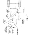
- Figure 7 diagrammatically illustrates a scanning electron beam computed tomography X-ray scanner.
- Figure 7 only shows an electron beam production and control assembly forming part of the scanner which also includes a detector array and a data acquisition and computer processing arrangement not shown in Figure 7.
- the electron beam production and control assembly which is generally indicated at 10 includes an overall housing 12 which defines an elongated vacuum-sealed chamber extending from its rearwardmost end 14 to its forwardmost end 16. This chamber may be divided into three sections, a rearwardmost chamber section 18, an intermediate section 20 and a forwardmost section 22. Gas is pumped out of the overall chamber by means of a vacuum pump 24 or other such suitable means.
- An electron gun 26 is located adjacent the rearwardmost end of chamber section 18 for producing a continuously expanding electron beam (see Figure 1) and for directing the latter through rearward chamber section 18 towards intermediate section 20 in a continuously outwardly expanding manner.
- the particular electron gun shown has a high vacuum impedance anode which permits differential pumping so that the residual gas pressure in the gun can be maintained at a much lower value than the gas pressure in the chamber.
- the electron gun includes its own vacuum pump 19.
- Intermediate chamber section 20 includes suitable means for bending the incoming beam into forwardmost chamber section 22 for impingement on an X-ray producing target, and for scanning the beam along the target, the X-rays being produced in a fan-like fashion (again see Figure 1 and also the Boyd patent and the Rand application).
- the target could be of any suitable material, in a preferred embodiment it is selected for high X-ray production, for a high melting point and for a reasonable price.
- the means in chamber section 20 includes a solenoidal focus coil, dipole deflecting coils and quadrupole coils.
- the quadrupole coils cooperate with the dipole deflecting coils by equalizing the focal lengths of the combination in the bend plane of the beam and in the transverse plane therethrough, regardless of the azimuthal angle of the bend, whereby to allow for a circular beam cross-section.
- Electron beam production and control assembly 10 as described thus far may be identical to the one described in the Boyd patent or the Rand patent application (except for the use of the quadrupole coils). Accordingly, chamber section 18 includes a series of ion collecting electrodes 28 which are described in detail in the Rand application. The chamber also includes a solenoidal focus coil and dipole deflecting coils which serve to bend the expanding beam into chamber section 22 and at the same time focus it onto the X-ray producing target, in a continuously converging manner from intermediate chamber section 20 to the target.
- assembly 10 includes means for neutralizing the space charge of the converging segment of the beam, that is, that portion in chamber 22, in a controlled manner sufficient to cause it to converge to a greater extent than it otherwise would in the absence of controlled neutralization. In this way, the beam is made to impinge the X-ray target in a smaller area than would be the case without controlled neutralization. Stated another way, the beam spot on the target is made smaller as a result of the controlled neutralization.
- controlled neutralization leading to ion aided focusing will be discussed in detail hereinafter.
- the presence of residual or ambient gas in the vacuum chamber along with the electron beam results in the production of ions.
- These ions function to neutralize the beam, as discussed more fully in the Rand patent application. This is entirely undesirable in the rearward section 18 of the chamber where the beam is expanding since neutralization would cause the beam to collapse. It is also undesirable elsewhere in the chamber if it takes place in a random, uncontrolled manner.
- controlled neutralization is taken advantage of to aid in the controlled collapse (convergence) of the beam in the forward section.
- the electron beam itself is made up of electrons having negative charges which produce electrostatic repulsive forces between the electrons.
- the beam produces its own magnetic field resulting in opposing attractive forces which are normally less in magnitude than the repulsive forces whereby the beam has a natural tendency to expand.
- the space charge of this beam is neutralized (by means of positive ions from ionized gas present in the chamber) in a manner which reduces the repulsive forces to a magnitude approximately equal to the magnitude of the attractive forces, whereby the area of the target impinged by the beam is limited in size only by the emittance of the beam.
- the beam is neutralized in a manner which reduces its repulsive forces to a magnitude below the magnitude of the attractive forces whereby the beam becomes self-focusing.
- the neutralizing means shown there includes a constant pressure gas supply, suitably nitrogen gas, which provides gas for injection into chamber section 22 in a controlled manner.
- the neutralizing means also includes a variable leak valve, a pressure sensor (vacuum gauge) disposed within chamber section 22, a gauge controller, a pressure controller and the vacuum pump 24.
- the gauge, gauge controller and pressure controller cooperate with the variable leak valve and with the gas supply and with the vacuum pump so as to either leak gas into or pump gas out of the chamber 22 in order to maintain the chamber at a preset gas pressure which will be discussed in detail hereinafter. For the moment it suffices to say that this gas pressure is selected to provide the desired ionization and hence controlled neutralization of the already converging beam.
- the parameter S is given by: where m is the electron rest mass (in volts)
- the multiple scattering parameter, g may be derived from a formula due to Lauer (E. J. Lauer, Lawrence Livermore Lab. Rept. UCID-16716, March 1975): where Z is the effective atomic number of the ambient gas,
- the numerical factor (10.46) in equation (3) derives from three factors: "8 ⁇ ,” the theoretical factor from the standard multiple scattering theory; " “ to allow for the fact that the standard theory refers to "1/e” half widths of distributions whereas in practice half widths at half maximum are measured; and "0.5,” since the multiple scattering distributions are projected onto a plane.
- Figure 2 is a schematic diagram of the electron beam envelope in the approximation that it is cylindrically symmetric. Any indication of deflection has been omitted for clarity.
- the converging beam in the electron gun 26 forms a waist close to the exit of the gun.
- the beam then expands until it reaches the magnetic lens, formed by the solenoid and dipole coils of the scanner referred to previously, after which it converges to a waist at the X-ray target 22.
- the emittance of the beam increases significantly due to multiple scattering in the ambient gas.
- the beam path is divided into three regions as shown in Figure 2.
- region I positive ions formed in the gas by the beam are removed from the beam by means of ion collecting electrodes as described in the Rand copending application. This ensures that inspite of the significant gas pressure, the neutralization of the beam is small and electrostatic repulsive forces dominate.
- the converging beam from the gun therefore forms a waist, near the gun exit, whose radius is determined by these forces.
- the beam then continues to expand because of the self-repulsion.
- region II near the lens, the beam is partially neutralized, but is of such a radius that self-forces are very small and its motion is essentially ballistic. In this region, the magnetic lens reconverges the diverging beam.
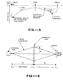
- Figure 3 shows schematically the form of the electrostatic potential wells formed by the beam.
- positive ions formed from the gas flow against the beam direction to the minimum of the potential distribution at the waist of the beam.
- ions are attracted out of the beam by the ion collecting electrodes.
- the initial potential well is bounded by a zero (ground) potential plane at the target. Ions therefore accumulate in this well until the neutralization reaches an equilibrium value. As new ions are formed, ions then leave the beam at the same rate, having acquired potential energy at their creation.
- Figure 4 shows schematically an approximate beam envelope model which may be used to calculate the multiple scattering term in equation (1).
- This model employs purely conical beam envelopes. The model is only expected to be inaccurate near the waists of the beam where there is very little contribution to the multiple scattering integral.
- the beam envelope equation (1) becomes, using equation (4)
- Equation (17) is of limited validity, but demonstrates explicitly how ion aided focusing influences the size of the beam spot at the target.
- positive ions are produced by ionization of the ambient gas in the scanner vacuum chamber, by the beam electrons.
- This gas is mainly nitrogen or other inert gas which is deliberately introduced into the chamber (see below).
- the ion production rate may be calculated assuming that the gas consists of single atoms, whereas most of the ions formed are probably N in the case of nitrogen. This point must be taken into account when the kinematics of the process are considered. Numerical examples below are calculated for nitrogen.
- N e I/ (e ⁇ c), where c is the velocity of light.
- c the velocity of light.
- equation (24) is modified by the image charges of the beam in the target.
- the new axial potential can then be calculated in the approximation that the target is a disc at zero potential and the beam is treated as a cylinder, radius r at each point.
- the potential as represented by equation (27) is illustrated schematically in Figure 3.
- the number of ions N I in a length l of beam increases at a rate given by where t is the average time required for an ion starting at radius r>r min to escape from the beam.
- Equation (31) may be written as w/v I where w is an effective width of the beam. (It is assumed that w depends only on the geometry of the beam and vacuum chamber and that w is constant in a given apparatus. The value of w is not calculated here, but it is found empirically as described later.)
- the multiple scattering parameter g is given by equation (3) and is proportional to gas pressure. All symbols have been defined previously.
- Figure 6 illustrates graphically the dependence of beam spot radius on gas pressure. At low pressures there is a plateau where stable space charge limited focusing occurs. The typical beam spot radius in this region for 600mA of 100kV electrons is 7.6 mm. As the pressure increases the beam becomes neutralized, its self repulsion decreases and the beam spot radius shrinks. The radius reaches a minimum close to the threshold pressure for ion aided focusing where the self forces of the beam are exactly balanced. Beyond this pressure the radius increases again because of multiple scattering in the gas. As the beam current decreases, so do the self-forces of the beam and the threshold pressure increase. Also plotted in Figure 6 is the beam spot radius for zero current which depends only on the initial beam emittance and multiple scattering. As can be seen the theory presented here is compatible with the experimental data although there is only limited information on the magnitude of the multiple scattering term.
- the settings are relatively insensitive to pressure and it is a simple matter to select acceptable operating conditions with chamber gas pressures ranging from 2.0 to 3.5 x 10 Torr at 600mA.
- the preferred pressure at this current is 2.7 x 10 6 Torr.
- 300mA even though the threshold pressure is higher, a slightly lower operating pressure is preferred.
- the acceptable pressure range is ultimately limited at its lower extreme to about 1 x 10 -6 Torr, where fluctuations due to target outgassing become significant, and at the upper extreme to about 4 x 10 -6 Torr, above which vacuum pressure in the gun becomes intolerably high. Both these limits could be extended by using higher speed vacuum pumps.
- the ion collecting electrode voltage be adjusted as well as the solenoidal coil current.
- the electrode voltage adjusts the beam size and divergence at the solenoid, which must be correct for optimum focusing.
- the neutralization fraction of the diverging beam is about 2%. To maintain this approximate value, the electrode voltage must be increased with gas pressure.
- a scanning electron beam computed tomography scanner with ion aided focusing of the electron beam has been described.
- the essential features of the scanner are (a) differential vacuum pumping at the gun anode, (b) separate vacuum pumps on the gun and main chamber, (c) ion collecting electrodes in the first section of the chamber, (d) a solenoidal focusing coil, (e) quadrupole focusing coils, (f) pressure control in the main chamber and (g) means of scanning the electron beam at a rate sufficient to prevent melting of the tungsten target but slow enough to retain ions in the potential well of the beam.
- the radius of the beam spot achieved is about 0.5 mm, more than one order of magnitude smaller than that obtained by any other known method.
Landscapes
- Apparatus For Radiation Diagnosis (AREA)
- X-Ray Techniques (AREA)
Applications Claiming Priority (2)
| Application Number | Priority Date | Filing Date | Title |
|---|---|---|---|
| US471199 | 1983-03-01 | ||
| US06/471,199 US4521901A (en) | 1983-03-01 | 1983-03-01 | Scanning electron beam computed tomography scanner with ion aided focusing |
Publications (2)
| Publication Number | Publication Date |
|---|---|
| EP0117729A2 true EP0117729A2 (fr) | 1984-09-05 |
| EP0117729A3 EP0117729A3 (fr) | 1986-03-19 |
Family
ID=23870662
Family Applications (1)
| Application Number | Title | Priority Date | Filing Date |
|---|---|---|---|
| EP84301181A Withdrawn EP0117729A3 (fr) | 1983-03-01 | 1984-02-23 | Dispositif et procédé de commande par ordinateur du balayage du faisceau électronique dans un appareil de tomographie utilisant les ions pour l'amélioration de la focalisation |
Country Status (4)
| Country | Link |
|---|---|
| US (1) | US4521901A (fr) |
| EP (1) | EP0117729A3 (fr) |
| JP (1) | JPS59192354A (fr) |
| CA (1) | CA1207920A (fr) |
Cited By (2)
| Publication number | Priority date | Publication date | Assignee | Title |
|---|---|---|---|---|
| RU2138879C1 (ru) * | 1998-07-29 | 1999-09-27 | Научно-технический центр "Исток" Государственного научно-исследовательского института Научно-производственного объединения "Луч" | Рентгеновская трубка |
| CN101515484B (zh) * | 2009-02-13 | 2011-08-24 | 中国科学院高能物理研究所 | 束流发射度均衡方法 |
Families Citing this family (39)
| Publication number | Priority date | Publication date | Assignee | Title |
|---|---|---|---|---|
| US4688241A (en) * | 1984-03-26 | 1987-08-18 | Ridge, Inc. | Microfocus X-ray system |
| US4631741A (en) * | 1984-04-05 | 1986-12-23 | Imatron, Inc. | Beam spot monitoring arrangement for use in a scanning electron beam computed tomography scanner and method |
| JPH0669450B2 (ja) * | 1986-10-06 | 1994-09-07 | イメイトロン インコ−ポレ−テツド | 走査電子ビームコンピュータトモグラフィスキャナおよびその操作方法 |
| US5197088A (en) * | 1991-05-03 | 1993-03-23 | Bruker Analytic | Electron beam x-ray computer tomography scanner |
| US5224137A (en) * | 1991-05-23 | 1993-06-29 | Imatron, Inc. | Tuning the scanning electron beam computed tomography scanner |
| US5193105A (en) * | 1991-12-18 | 1993-03-09 | Imatron, Inc. | Ion controlling electrode assembly for a scanning electron beam computed tomography scanner |
| US5289519A (en) * | 1991-12-18 | 1994-02-22 | Imatron, Inc. | Rotatable ion controlling electrode assembly with no offset or deflection of low energy electrons for a scanning electron beam computed tomography scanner |
| US5274690A (en) * | 1992-01-06 | 1993-12-28 | Picker International, Inc. | Rotating housing and anode/stationary cathode x-ray tube with magnetic susceptor for holding the cathode stationary |
| US5438605A (en) * | 1992-01-06 | 1995-08-01 | Picker International, Inc. | Ring tube x-ray source with active vacuum pumping |
| US5241577A (en) * | 1992-01-06 | 1993-08-31 | Picker International, Inc. | X-ray tube with bearing slip ring |
| US5386445A (en) * | 1993-12-14 | 1995-01-31 | Imatron, Inc. | Method and apparatus for electron beam focusing adjustment by electrostatic control of the distribution of beam-generated positive ions in a scanning electron beam computed tomography scanner |
| US5712889A (en) * | 1994-08-24 | 1998-01-27 | Lanzara; Giovanni | Scanned volume CT scanner |
| DE19513289C2 (de) * | 1995-04-07 | 1998-05-14 | Siemens Ag | Röntgenröhre mit einer Verstelleinheit |
| US6628745B1 (en) * | 2000-07-01 | 2003-09-30 | Martin Annis | Imaging with digital tomography and a rapidly moving x-ray source |
| US6633040B1 (en) * | 2002-04-25 | 2003-10-14 | International Business Machines Corporation | Solenoid electron beam lenses with high demagnification and low aberrations |
| US6670625B1 (en) | 2002-06-18 | 2003-12-30 | Ge Medical Systems Global Technology Company, Llc | Method and apparatus for correcting multipole aberrations of an electron beam in an EBT scanner |
| US7447536B2 (en) * | 2002-11-12 | 2008-11-04 | G.E. Medical Systems Global Technology Company, Llc | System and method for measurement of local lung function using electron beam CT |
| US6789943B2 (en) * | 2002-11-12 | 2004-09-14 | Ge Medical Systems Global Technology Company, Llc | Method and apparatus for scatter measurement using an occluded detector ring |
| NL1024724C2 (nl) | 2002-11-12 | 2005-05-04 | Ge Med Sys Global Tech Co Llc | Systeem en werkwijze voor het meten van een lokale longfunctie onder gebruikmaking van elektronenstraal CT. |
| US6842499B2 (en) * | 2002-11-15 | 2005-01-11 | Ge Medical Systems Global Technology Company, Llc | Method and apparatus for connecting temporally separated sinograms in an EBT scanner |
| US6864633B2 (en) * | 2003-04-03 | 2005-03-08 | Varian Medical Systems, Inc. | X-ray source employing a compact electron beam accelerator |
| US6950493B2 (en) * | 2003-06-25 | 2005-09-27 | Besson Guy M | Dynamic multi-spectral CT imaging |
| US7049616B2 (en) * | 2004-05-17 | 2006-05-23 | General Electric Company | Methods, apparatus, and software for adjusting the focal spot of an electron beam |
| DE102004061347B3 (de) * | 2004-12-20 | 2006-09-28 | Siemens Ag | Röntgen-Computertomograph für schnelle Bildaufzeichung |
| EP1868559B1 (fr) | 2005-04-05 | 2016-05-04 | Membrane Protective Technologies, Inc. | Methode pour diminuer la perte de fonction de cellules reproductrices |
| DE102005018329B4 (de) * | 2005-04-20 | 2008-10-30 | Siemens Ag | Detektormodul für Röntgen- oder Gammastrahlung auf Basis von Wellenleitern |
| US7627087B2 (en) * | 2007-06-28 | 2009-12-01 | General Electric Company | One-dimensional grid mesh for a high-compression electron gun |
| DE102007035177A1 (de) * | 2007-07-27 | 2009-02-05 | Siemens Ag | Computertomographie-System mit feststehendem Anodenring |
| DE102007036038A1 (de) | 2007-08-01 | 2009-02-05 | Siemens Ag | Röntgen-Computertomograph der 5ten Generation |
| JP4650642B2 (ja) * | 2007-12-13 | 2011-03-16 | 株式会社エーイーティー | X線発生装置 |
| US7809114B2 (en) * | 2008-01-21 | 2010-10-05 | General Electric Company | Field emitter based electron source for multiple spot X-ray |
| US7826594B2 (en) * | 2008-01-21 | 2010-11-02 | General Electric Company | Virtual matrix control scheme for multiple spot X-ray source |
| US7801277B2 (en) * | 2008-03-26 | 2010-09-21 | General Electric Company | Field emitter based electron source with minimized beam emittance growth |
| US7881436B2 (en) | 2008-05-12 | 2011-02-01 | General Electric Company | Method and apparatus of differential pumping in an x-ray tube |
| JP2011528273A (ja) | 2008-07-16 | 2011-11-17 | ボリス オレパー | 電子ビームスキャナを含む照射システム |
| US8588372B2 (en) * | 2009-12-16 | 2013-11-19 | General Electric Company | Apparatus for modifying electron beam aspect ratio for X-ray generation |
| DE102012005767A1 (de) | 2012-03-25 | 2013-09-26 | DüRR DENTAL AG | Phasenkontrast-Röntgen-Tomographiegerät |
| GB201303517D0 (en) * | 2013-02-27 | 2013-04-10 | Enxray Ltd | Apparatus for the generation of low-energy x-rays |
| US9490099B2 (en) | 2014-08-20 | 2016-11-08 | Wisconsin Alumni Research Foundation | System and method for multi-source X-ray-based imaging |
Family Cites Families (7)
| Publication number | Priority date | Publication date | Assignee | Title |
|---|---|---|---|---|
| GB1084015A (en) * | 1964-05-29 | 1967-09-20 | Atomic Energy Authority Uk | Flash x-ray tubes |
| US3510713A (en) * | 1966-07-19 | 1970-05-05 | Willard H Bennett | Method of and appparatus for producing a highly concentrated beam of electrons |
| US4119855A (en) * | 1977-07-08 | 1978-10-10 | Massachusetts Institute Of Technology | Non vacuum soft x-ray lithographic source |
| GB2015816A (en) * | 1978-03-03 | 1979-09-12 | Emi Ltd X | X-ray tubes |
| GB2034965B (en) * | 1978-09-14 | 1982-11-24 | Emi Ltd | Electron beam focussing in x-ray tubes |
| DE24325T1 (de) * | 1979-08-16 | 1983-03-03 | General Electric Co., Schenectady, N.Y. | Roentgentomographiesystem mit elektronischer abtastung. |
| US4352021A (en) * | 1980-01-07 | 1982-09-28 | The Regents Of The University Of California | X-Ray transmission scanning system and method and electron beam X-ray scan tube for use therewith |
-
1983
- 1983-03-01 US US06/471,199 patent/US4521901A/en not_active Expired - Lifetime
-
1984
- 1984-02-15 CA CA000447452A patent/CA1207920A/fr not_active Expired
- 1984-02-23 EP EP84301181A patent/EP0117729A3/fr not_active Withdrawn
- 1984-03-01 JP JP59039713A patent/JPS59192354A/ja active Pending
Cited By (2)
| Publication number | Priority date | Publication date | Assignee | Title |
|---|---|---|---|---|
| RU2138879C1 (ru) * | 1998-07-29 | 1999-09-27 | Научно-технический центр "Исток" Государственного научно-исследовательского института Научно-производственного объединения "Луч" | Рентгеновская трубка |
| CN101515484B (zh) * | 2009-02-13 | 2011-08-24 | 中国科学院高能物理研究所 | 束流发射度均衡方法 |
Also Published As
| Publication number | Publication date |
|---|---|
| CA1207920A (fr) | 1986-07-15 |
| US4521901A (en) | 1985-06-04 |
| EP0117729A3 (fr) | 1986-03-19 |
| JPS59192354A (ja) | 1984-10-31 |
Similar Documents
| Publication | Publication Date | Title |
|---|---|---|
| US4521901A (en) | Scanning electron beam computed tomography scanner with ion aided focusing | |
| EP0107451B1 (fr) | Dispositif et procédé pour commander le balayage du faisceau électronique dans un appareil de tomographie à ordinateur | |
| US5932882A (en) | Ion implanter with post mass selection deceleration | |
| US5969366A (en) | Ion implanter with post mass selection deceleration | |
| US9214313B2 (en) | Ion source with independent power supplies | |
| US3619684A (en) | Ion source | |
| Müller et al. | Emission properties of electron point sources | |
| US3955091A (en) | Method and apparatus for extracting well-formed, high current ion beams from a plasma source | |
| EP1826809A1 (fr) | Appareil optique à particules comportant une source d'ions à gaz | |
| Belchenko et al. | Inductively driven surface-plasma negative ion source for N-NBI use | |
| CN116710284A (zh) | 使用粉末床熔融的增材制造 | |
| US10431415B2 (en) | X-ray tube ion barrier | |
| US3745342A (en) | Electron beam apparatus comprising a cathode to be heated by an energy beam | |
| US4139772A (en) | Plasma discharge ion source | |
| EP0127983A2 (fr) | Balayage de faisceau-électronique dans un appareil de tomographie à ordinateur | |
| US6670625B1 (en) | Method and apparatus for correcting multipole aberrations of an electron beam in an EBT scanner | |
| Liebl | Ion optics of ion microprobe instruments | |
| US4087720A (en) | Multi-beam, multi-aperture ion sources of the beam-plasma type | |
| US20230065373A1 (en) | Particle beam device, method for operating the particle beam device and computer program product | |
| US4983845A (en) | Apparatus operating with contact ionization for the production of a beam of accelerated ions | |
| Wroński | Ion energy distributions in a special glow-discharge ion source | |
| Mason et al. | The dependence of electron gun performance on filament material | |
| GB2307095A (en) | An ion implanter with post mass selection deceleration | |
| US4171462A (en) | Linear electron beam gun evaporator having uniform electron emission | |
| Gaines et al. | An improved annular-shaped electron gun for an X-ray generator |
Legal Events
| Date | Code | Title | Description |
|---|---|---|---|
| PUAI | Public reference made under article 153(3) epc to a published international application that has entered the european phase |
Free format text: ORIGINAL CODE: 0009012 |
|
| AK | Designated contracting states |
Designated state(s): DE FR GB IT NL SE |
|
| PUAL | Search report despatched |
Free format text: ORIGINAL CODE: 0009013 |
|
| AK | Designated contracting states |
Kind code of ref document: A3 Designated state(s): DE FR GB IT NL SE |
|
| STAA | Information on the status of an ep patent application or granted ep patent |
Free format text: STATUS: THE APPLICATION IS DEEMED TO BE WITHDRAWN |
|
| 18D | Application deemed to be withdrawn |
Effective date: 19861120 |
|
| RIN1 | Information on inventor provided before grant (corrected) |
Inventor name: RAND, ROY EDWARD |