EP0117751A2 - Vorrichtung zum Stumpfschweissen von Stahlbändern mit einem Laserstrahl in einer Stahlbandverarbeitungsstrasse - Google Patents
Vorrichtung zum Stumpfschweissen von Stahlbändern mit einem Laserstrahl in einer Stahlbandverarbeitungsstrasse Download PDFInfo
- Publication number
- EP0117751A2 EP0117751A2 EP84301263A EP84301263A EP0117751A2 EP 0117751 A2 EP0117751 A2 EP 0117751A2 EP 84301263 A EP84301263 A EP 84301263A EP 84301263 A EP84301263 A EP 84301263A EP 0117751 A2 EP0117751 A2 EP 0117751A2
- Authority
- EP
- European Patent Office
- Prior art keywords
- laser beam
- filler wire
- line
- laser
- clamp
- Prior art date
- Legal status (The legal status is an assumption and is not a legal conclusion. Google has not performed a legal analysis and makes no representation as to the accuracy of the status listed.)
- Granted
Links
Images


Classifications
-
- B—PERFORMING OPERATIONS; TRANSPORTING
- B23—MACHINE TOOLS; METAL-WORKING NOT OTHERWISE PROVIDED FOR
- B23K—SOLDERING OR UNSOLDERING; WELDING; CLADDING OR PLATING BY SOLDERING OR WELDING; CUTTING BY APPLYING HEAT LOCALLY, e.g. FLAME CUTTING; WORKING BY LASER BEAM
- B23K26/00—Working by laser beam, e.g. welding, cutting or boring
- B23K26/02—Positioning or observing the workpiece, e.g. with respect to the point of impact; Aligning, aiming or focusing the laser beam
- B23K26/04—Automatically aligning, aiming or focusing the laser beam, e.g. using the back-scattered light
-
- B—PERFORMING OPERATIONS; TRANSPORTING
- B23—MACHINE TOOLS; METAL-WORKING NOT OTHERWISE PROVIDED FOR
- B23K—SOLDERING OR UNSOLDERING; WELDING; CLADDING OR PLATING BY SOLDERING OR WELDING; CUTTING BY APPLYING HEAT LOCALLY, e.g. FLAME CUTTING; WORKING BY LASER BEAM
- B23K26/00—Working by laser beam, e.g. welding, cutting or boring
- B23K26/20—Bonding
- B23K26/21—Bonding by welding
- B23K26/24—Seam welding
- B23K26/26—Seam welding of rectilinear seams
-
- B—PERFORMING OPERATIONS; TRANSPORTING
- B23—MACHINE TOOLS; METAL-WORKING NOT OTHERWISE PROVIDED FOR
- B23K—SOLDERING OR UNSOLDERING; WELDING; CLADDING OR PLATING BY SOLDERING OR WELDING; CUTTING BY APPLYING HEAT LOCALLY, e.g. FLAME CUTTING; WORKING BY LASER BEAM
- B23K2103/00—Materials to be soldered, welded or cut
- B23K2103/02—Iron or ferrous alloys
- B23K2103/04—Steel or steel alloys
- B23K2103/05—Stainless steel
Definitions
- the present invention relates to an apparatus for butt welding steel strips by means of a laser beam (hereinafter referred to as "laser butt welding apparatus") in a steel strip-processing line.
- laser butt welding apparatus an apparatus for butt welding steel strips by means of a laser beam (hereinafter referred to as "laser butt welding apparatus") in a steel strip-processing line.
- steel strips are jointed together at an entry section of the line, and fed to a latter stage processing and continuously treated and produced.
- the steel strips have been conventionally jointed by a seam welding machine, a flash butt welding machine, an arc welding machine such as TIG arc welding machine.
- These welding methods have their own peculiar characteristics respectively.
- the seam welding is characterized in that the welding is possible at a high speed in a short time, but the thickness of the welded portion becomes 180-130% of that of the base metal because the steel strips are welded by piling their edges one upon another. Therefore, the welded portion can not be rolled in a coil by taking the problem such as buckling into account.
- this method has the defect that the surface must be ground prior to the welding. Further, in the case of the welding of thin steel strips, since the strips are pressed by means of electrode wheels, this method has the drawback that the profile of junction and the vicinity thereof are deteriorated.
- the flash butt welding can make the welding time shorter than the seam welding because the steel strips are welded at one time over their whole width in the former method, but thin steel strips are likely to be bent due to upsetting step, so that this method has the defect that it is applicable to the relatively thick steel strips of not less than 1.6 mm, but is not applicable to the thin steel strips. It also has the defect that it is inapplicable to special steels such as silicon steel, stainless steel, high carbon steel because of oxidation, a large heat input and the coarse grain growth at the welded portion and heat affected zone when the flashing is effected. As a result, the use of flash butt welding is generally restricted to the welding of the low carbon steel strips of not less than 1.6 mm in thickness.
- TIG arc welding it is possible to improve the quality of the welded portion through addition of a filler wire or the like, and therefore, this method can be used for stainless steel.
- the heat input is large, it has the defect that it is inapplicable to the material such as the silicon steel in which the coarse grains are likely to grow. Further, it also has the defects that the welding speed is slow, and the welding time is long.
- the welding is done at a beam diameter of about 0.2-0.8 mm with respect to the gap of 0.05-2 mm between the butted edges of the steel strips.
- the edge portions of the steel strips are cut by means of a shear, but there is the possibility that a uniform lateral gap between the edges of the steel strips is not formed, or the track of the laser beam is not coincident with the center line of the gap due to a poor precision of the shear.
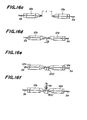
- Fig. 27(a) illustrates the shape of the gap formed when the edges of the steel strips are butted with each other.
- Reference numerals Sa and Sb are preceding and trailing steel strips
- reference numerals 702 and 703 are the track of the laser beam and the center line of the gap between the butted edges of the steel strips respectively.
- the welding is carried out by running the laser beam along the straight line 702 in the transverse direction of the steel strips, while being kept at a constant position in the longitudinal direction without being adjusted to be longitudinally displaced, and by supplying a filler wire at a constant rate. But, the fused filler wire is lacking at the portions a and c, while to the contrary, the fused filler wire is in excess at the portions b and d.
- the gaps at the positions a and c are not completely filled with the fused filler wire and an amount of the filler wire fused is not sufficient and the welding strength is poor. With respect to the positions b and d having the excessively fused filler wire, such a method is economically unfavorable.
- An object of the present invention is to provide an automatic laser butt welding apparatus for butt welding steel strips in a steel-processing line by using a laser beam as a heat source.
- the object of the invention is to provide a laser butt welding apparatus usable for welding almost all kinds of the steels, for instance, special steels such as silicon steel, stainless steel or the like, a plated steel such as a galvanized steel or the like, and high tensile strength steels.
- It is a still further object of the invention is to provide a laser butt welding apparatus which can stably provide a satisfactory welding strength even when the gap between the butted edges of the steel strips to be welded together is not uniform.
- Still further object of the invention is to provide a method of laser butt welding which can stably provide an optimum welding strength even when the gap between the butted edges of the steel strips to be welded together is ununiform.
- a laser butt welding apparatus comprising a pair of clamp means of an inlet clamp means and an outlet clamp means, at least one of which is movable forward and rearward along the steel strip-feed line direction and which are adapted to clamp the edge portions of a preceding steel strip and a trailing steel strip, each of said inlet and outlet clamp means having an upper clamp and a lower clamp, a shear which is advanceable and retractable between the pair of the clamp means in a perpendicular direction to the line and cuts the edge portions of the preceding and trailing steel strips, means for butting the cut faces of the preceding and trailing steel strips while being clamped by means of the clamp means, means for feeding a filler wire at a weld zone at which the laser beam is condensed, and a laser torch mounting a reflector adapted to bend a laser beam irradiated from a laser oscillator placed on an off-line and a condenser adapted to condense the laser beam
- an apparatus for performing the above laser butt welding method comprising a filler wire supply means, a laser torch equipped with a driving means adapted to control the displacement of the laser torch in a steel strip processing direction of the members to be welded together, a detecting means for detecting the size and the location of the center line of the gap between the butted edges of the members, a controller for controlling the location of the laser torch in the line direction and the supply rate of the filler wire or the supply amount of the filler wire based on the detection signal from the detecting means in such a manner that the laser beam may be run along the center line of the gap between the butted edges of the members, and the supply rate or the supply amount of the filler wire may be proportional to the size of the gap.
- Top ends of the upper clamps 12a and 12b of the inlet and outlet clamp means 3a and 3b are extended a little longer toward a shear- running line than those of the lower clamp, means 15a and 15b, so that the steel strips Sa and Sb to be cut are clamped between the tips of the upper clamp means 12a, 12b and the lower blades 8.
- a station 100 for checking the performances of an optical system for irradiating a laser beam on a weld zone of the steel strips is provided at the lower clamp base 15b on an off-line.
- a reference numeral 101 is a table having a slit just under the laser torch.
- Numeral 103 is a sample plate which is secured to the table 101 by means of press plates 104 and bolts 105.
- the table 101 is joined to the lower clamp base 15b, but it may be supported by a base 33.
- An arm 17 is provided on the inlet clamp 3a.
- the inlet clamp 3a When the inlet clamp 3a is moved toward the outlet clamp 3b by means of the cylinder 16, it is stopped upon contact with the stopper 18 and the forward displacement thereof is restricted.
- the stopper 18 is located apart from the lower bent edge side of the arm 17 at a slightly larger distance as that of the gap between the edge faces of the strips cut by the shear.
- a pressure detector 25 such as a load cell is provided at a contact face between the stopper 18 and the arm 17, so that the stopper 18 is movable by being guided with guide means 26.
- the stopper serves to set the gap between the butted edges of the shear-cut preceding and trailing steel strips smaller than the diameter of the filler wire. That is, a screw shaft 27 is screwed to the lower portion of the stopper 18, and the screw shaft is adapted to be rotated for shifting the position of the stopper 18 by actuating the motor 32 via bevel gears 28 and 29, a shaft 31 and bevel gears 30 and 30'.
- a stopper-positioning system comprising the bevel gears 28, 29, 30 and 30' and the shafts 27 and 31 are arranged onto a lower base 33.
- the clamp means 3a provided with the arm 17 is movable by means of the cylinder 16.
- two stoppers 18 are driven by means of a single motor 32, but as a matter of course, they may be driven independently by means of two motors.
- a reference numeral 201 is a condenser which is attached to a torch 202.
- a reference numeral 203 is a blacket attached to the torch 202 and engaged with the screw axis 204 at its other end.
- the screw shaft 204 is supported by the bearing 205 at both ends thereof and connected to a motor 206.
- a reference numeral 207 is a torch holder which is adapted to ascend and descend while being guided by a guide means 208. This torch holder 207 also serves to guide the ascending and descending of the torch 202.
- a cylinder 209 is attached to a reflector base 210 and adapted to ascend and descend the torch holder 207.
- Reference numerals 211 and 212 are bender reflector attached to the reflector base 210, and adapted to bend the laser beam to a desired direction.
- the reflector base 210 is guided by a carriage 214 and can be moved in a direction perpendicular to the torch running direction by a motor 220.
- the carriage 214 is adapted to be moved in a direction perpendicular to the processing line by means of a guide means 215, a motor 216, a screw shaft 217 connected to the motor 216, bearings 218 of the screw shaft 217, and a nut 219 screwed to the screw shaft 217.
- a reference numeral 600 is a filler wire feed means which will be explained in detail with reference to Figs. 24 and 25.
- the filler wire feed means is attached to the torch frame 207.
- this filler wire feed means may be integrally attached to the torch 202 and adapted to move together with the torch.
- a center clamp 300 will be explained with reference to Figs. 3, 13 and 14.
- the center clamp 300 is arranged at a side opposite to the laser torch at the butting portion of the preceding and trailing steel strip edge portions, and includes a backing bar 301 provided with a bag-like groove 302.
- the center clamp further comprises cylinders 303, guide rods 304 and guides 305, and is adapted to be contacted with or separated from the back face of the strips to be jointed.
- Reference numerals 306, 307 and 308 are a backing bar supporting base, a light absorbing member, and a coolant passage respectively.
- the backing bar 301 is designed to have such a size that the preceding steel strip and the trailing steel strip are fully sandwiched between it and the upper clamps 12a and 12b when elevated.
- This bag-like groove 302 prevents the laser beam passed through the weld zone from reflecting and dispersing to the outside and further the safety is assured by preventing the laser beam from leaking to the outside by the provision of a light absorbing member 307 onto the face of a supporting base 306 onto which the laser beam is irradiated.
- the filler wire is applied to the weld zone as follows:
- the length A is a contact length required for properly placing the filler wire in the gap set smaller than the diameter of the filler wire.
- the side edges of the shear-cut preceding and trailing steel strips properly serve to locate the filler wire fed in the length l.
- the filler wire feed means comprises a filler wire reel 601 for storing the filler wire, a feed rolls 607 for feeding the filler wire stored in the reel through rotation by means of a motor 608 while the filler wire being sandwiched therebetween, and a guide tube 604 for guiding the filler wire toward the weld zone.
- the reel and the feed rolls are attached to the torch holder 207 through support means 603 and 602 respectively, while the guide tube 604 is attached to the torch by support means 605 and 606.
- the guide tube is designed to have an inner diameter of substantially the same as the outer diameter of the filler wire, and it serves to guide the filler wire fed from the feed rolls 607 toward the weld zone, while straightening the curved or bent filler wire.
- it is necessary to open the clamp means clamping the preceding and trailing steel strips immediately after the completion of the welding so as to make the weld cycle time as short as possible and re-start the processing line.
- the torch when the welding has been completed must be retracted to a position above the clamps by a specific distance before the clamping -is opened so that the interruption of the torch to the clamp may be avoided [Figs. 26(a) and 26(b)].
- the ascending and descending cylinder 209 is actuated to lift the torch 202.
- the upper movement of the torch may cause the filler wire to be bent between the guide tube 604 and the filler rolls 607.
- Such bent wire may not recover the original straightly form even if it is passed through the guide tube, so that the filler may not be fed to the weld zone in an appropriate state.
- the distance between the feed rolls 607 and the guide tube 604 is too long, the wire having a fine diameter is low in the rigidity and such a wire is liable to be bent between the roller and the tube due to the resistance at the guide tube.
- Fig. 25 shows another embodiment of the filler wire feed means according to the invention when it is anticipated that the filler wire is bent at the time of the upper movement of the torch.
- a reference numeral 601 is a wire reel for storing the filler wire
- a reference numeral 607 is means (rolls) adapted for feeding the filler wire stored in the reel while being rotated by a motor 608 sandwiching the filler wire therebetween.
- a reference numeral 604 is a guide tube adapted for guiding the filler wire fed by the filler rolls 607 into the weld zone and adjustable by rolls 609. The inner diameter of the guide tube is designed to be substantially the same as the outer diameter of the filler wire, so that the filler wire is fed onto the weld zone, while curved or bent filler wire is being straightened.
- the filler wire feed means 600 which comprises the filler wire reel 601, a filler wire feed rolls 607 and the guide tube 604 is integrally attached to the torch 202 by support means 603, 602, 605.
- Reference numeral 605 is support means for supporting the guide tube 604 and may be adjustable in terms of its inclination angle and the distance up to the torch by an appropriate means (not shown).
- the cylinder 209 (see Figs. 11 and 12) is actuated.
- the filler wire feed means is integrally fitted to the torch, it is ascended or descended together with the torch.
- the positional interrelation between the wire reel, feed rolls and the guide tube is not varied irrespective of the torch movement.
- the filler wire is not bent or curved between the feed rolls 607 and the guide tube 604. Further, by reducing the distance between the feed rolls and the guide tube, it is possible to prevent the wire having a small diameter from bending between the feed rolls 607 and the guide tube 604.
- edge portions of the steel strips are prevented from being deformed as shown in Fig. 15 by clamping the edge portions between the extended tip portions of the upper clamps and the center clamp. Thus, an excellent welded joint is obtained.
- the motor 216 is actuated to drive the torch laser in the transverse direction of the steel strip.
- a detector not shown detects the side end of the strip
- the filler wire begins to be fed, and then a shutter housed in the laser oscillator 1 is opened to irradiate the laser beam onto the side of the laser torch 4 after a predetermined time interval from the filler wire feeding.
- the laser beam is bent in a direction parallel to the line by means of a bender reflector 211, and is next bent in a direction vertical to the line by means of a bender reflector 212 and then passed through the condenser 201 to be focused onto a weld zone and to commerse the welding while fusing the fed filler wire.
- the laser torch is run in the transverse direction of the strips.
- the feeding of the filler wire is stopped and then the irradiation of the laser beam after a predetermined time interval since the filler wire feeding is stopped. Then, the torch is carried to the retracted position and stopped.
- Fig. 27(a) shows the supply rate of the filler wire and/or the running speed of the torch.
- Fig. 27(b) shows the control way that the filler wire supply rate may be in proportion to the size of the gap.
- the filler wire supply rate is controlled as follows:
- a reference numeral 701 is a light irradiator which is located over the butted edges of the steel strips. It may be located under and on the side of the butted steel strips. The light irradiator is arranged to irradiate the butted edges with a light beam.
- a reference numeral 702 is a light receiving element such as a photo diode array for detecting the size and the center of the gap between the butted edges through which the light is reflected or passed.
- the light irradiator 701 and the light receiving element 702 are attached to the torch holder and adapted to be moved together with the movement of the torch.
- the tip of the light receiving element 702 is positioned slightly in advance on a welding line.
- a reference numeral 703 is a control means including an arithmetic circuit and a memory means, which controls the center of the laser beam to coincide with the center line of the gap between the butted edges of the strips and the rate of the filler wire supplied to be in proportion to the size of the gap based on the detected signal from the light receiving element 702. That is, the size of the gap and the location of the center line of the gap are determined based on the signal from the light receiving element in the arithmetic circuit and stored in the memory means.
- the information from the memory means is outputted to the motor 220 and the motor 608 to control the beam center and the amount of the filler wire.
- the memory means may be omitted.
- the rate of the filler wire supplied is controlled to be varied as shown in Fig. 27(b). In such a manner, the laser beam is run at the center line of the gap between the butted edges of the steel strips and the filler wire is supplied in a necessary and enough amount to fill the gap depending upon the size of the gap.
- the welding strength is conspicuously improved as compared with the prior art.
- the repeated flexing strength test was carried out, and the broken rate was determined when each steel strip having a welded line was rolled. The results are shown in Figs. 29 and 30. From these figures it can be seen that the repeated flexing strength is far more excellent in the present invention than in the conventional case, and the broken rate of the re-rolling in the invention is improved more than 2 times than in the case of the conventional case.
- an optimum welding strength can be stably obtained irrelative to the shape of the gap between the butted edges of the members to be jointed and without causing the deficiency and excess of the amount of the fused filler wire.
- the focused position in the line direction of the laser beam path posterior to the reflector 212 can be varied merely by shifting the reflector 212 in a horizontal direction.
- the beam path may be slightly varied depending upon the circumferential temperature, a leading period of time of the oscillator, a temperature of the reflector, and the like, and consequently there is the possibility that the beam point focused by the condenser is shift slightly. Since the shift component of the focus in the direction perpendicular to the processing line is no problems because it is in a weld line, while if the focus is shifted in the direction parallel to the line, it is deviated from the butting line to form weld profile as shown in Fig. 20. Since this form of the joint has a notch in the lower side, it is weak in bending and unacceptable.
- the laser butt welding apparatus of the invention in order to facilitate the positioning of the focus in the line direction, the laser beam path is bent in parallel to the line at least one time and then the optical system after such a bending step is moved to a horizontal direction, whereby the focus can be moved in a direction parallel to the line by the same distance as the amount of the optical system moved without moving the focus to the vertical direction and the direction perpendicular to the line and the operation for positioning the focus can be very easily effected.
- a reference numeral 401 is a first reflector adapted to bend the laser beam 213 incident thereupon in a direction perpendicular to the line, in the vertical direction to the line
- a reference numeral 402 is a second reflector adapted to bend the laser beam thus vertically bent in the direction parallel to the line
- a reference numeral 403 is a condensing reflector adapted to focus the laser beam in parallel to the line thus bent, at a weld zone.
- the focus is shifted by the same distance as this displacement only in the direction parallel to the line without being shifted in the vertical direction or perpendicular direction to the line.
- the focusing is carried out by moving the reflector 402 and the condensing reflector 403 as one set in a vertical direction.
- Fig. 22 shows another embodiment using a condensing reflector.
- a reference numeral 501 is a first reflector adapted to bend the laser beam 213 incident thereupon in the direction perpendicular to the line, in the direction parallel to the line, a reference numeral 502 is a second reflector adapted to vertically bend the laser beam thus bent, in the direction parallel to the line, a reference numeral 503 is a third reflector adapted'to bend the thus vertically bent laser beam in the direction parallel to the line, and a reference numeral 504 is a condensing reflector adapted to focus the laser beam at the weld zone.
- the focus point is shifted by the same distance as displacement of the condenser reflector in the parallel direction without being displaced vertically or in the direction perpendicular to the line.
- the focusing is carried out by vertically shifting the reflector 503 and the condensing reflector as one set.
- the cylinder 209 is actuated to lift and return the laser torch to the original position, and the other means are returned to their original locations. Thereby, one weld process is completed.
- the cut lines formed through the above cutting operation are in parallel to each other and straight in the case of the laser welding. That is, when the laser beam is condensed by the condenser, the diameter of the laser beam at the focus is varied according to the focal length of the condenser, for instance, when a condenser having a focal length of 5 inches is used, said diameter is as extremely small as 0.15 mm. Therefore, according to the laser butt welding, it is possible to increase the energy density and to effect a high speed welding, but an extremely high precision is required in butting of the materials to be welded.
- the cut lines of the materials to be welded are curved, a ununiform clearance is created even if the butting is effected at a very high precision.
- the cut line is more or less curved as shown in Fig. 18 in a transverse direction of the plate.
- the curved degree of the cut line depends upon the material, clamping way, shear or the like, but it is observed that the cut line is curved at about 0.1 mm in the case of a steel plate having a thickness of 1.0-3.0 mm.
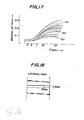
- Fig. 17 shows the relation of the distance l from the edge of the upper clamp to the tip face of the upper blade to a value AG obtained by subtracting the minimum cut gap (Gmin) from the maximum cut gap (Gmax) among the cut gaps measured in the transverse direction of the strip (see Fig. 18).
- Table 1 shows the results obtained when the above described cut edge portions are butted and the butted portion is subjected to the laser butt welding.
- the excellent welding is possible in a range of 2 being not more than 7 mm. In a range of 7 ⁇ l ⁇ 15, the rupture at the welded portion is likely to be caused and there is problem in plate-passing, rolling or other processing steps of the strip.
- the zones (a), (b) and (c) correspond to the steel strips having thickness (t) of 1.0 mm, 1.6 mm and 3.0 mm respectively.
- the welding conditions in the test of Table 1 are as follows, that is a laser power is 1 kw, the materials are cold-rolled steel strip and hot-rolled steel strip (low carbon steel) and the welding speed is 1.0-3.0 m/min.
- the marks (A) means that the tensile strength when the welded joint portion is ruptured, is about 80-100% of that of the base metal and the mark (x) means about 40-80% thereof.
- Fig. 19 shows a relation of tan a (a: shear rake angle) to the above described value ⁇ G and the results obtained by performing the tensile test with respect to the welded portions formed by effecting the laser butt welding by using the cut strips under the condition of tan a and ⁇ G shown in Fig. 19.
- the curve of the cut line may be more reduced by making tan a smaller and the good welded joint can be stably obtained.
- the lower limit for the practical range of tan a is about 4 t/1,000. That is, the lower limit is 2.4/1,000 in the case of 0.6 mm in thickness, 12/1,000 in the case of 3 mm in thickness and 18/1,000 in the case of 4.5 mm in thickness.
- the station 100 for checking the performances of the optical system is provided at a position on the line extended from the laser torch running line for welding, where the passing of the steel strip is not interrupted, so that the above described working for the condenser can be carried out during the time when the steel strips are passed on the line, whereby the productivity is increased.
- the station for checking the performances of the optical system is used as follows:
- Fig. 6(b) is another embodiment of the station for checking the performances of the optical system in which the lower portion of the slit is closed for preventing the penetration or scattering of the laser beam.
- Table 2 shows the comparison of the welding time of the laser butt welding according to the invention with the TIG arc welding.
- the comparison was made with respect to two kinds of steel strips having a thickness of 1.0 mm and 2.3 mm.
- the laser power is 1 or 3 kw and torch-running distance in the laser butt welding and TIG arc welding is 1.5 m. It is understood from this table that with respect to the same thickness of the steel strips, the welding time in the laser butt welding is less than 0.5 time as short as that of the TIG arc welding.
- Table 3 shows the test results obtained in the tensile tests with respect to the welded portions of various steel strips by using the laser butt welding apparatus according to the present invention.
- the width of the test steel strip is 914-1,067 mm, and five test pieces are cut off in the width direction and the test is made with respect to these test pieces. In all the test pieces, the rupture occurs at the base metal and the welding strength is excellent.
- Table 4 shows the results on the welding test using the apparatus according to the invention while the l, L and ⁇ are varied. As may be understood from this table, it is preferable that the interrelation between the torch and the filler wire feed means is set such that l is in a range of 1-5 mm, L is not more than 20 mm and ⁇ is not more than 35°.
Landscapes
- Physics & Mathematics (AREA)
- Optics & Photonics (AREA)
- Engineering & Computer Science (AREA)
- Plasma & Fusion (AREA)
- Mechanical Engineering (AREA)
- Laser Beam Processing (AREA)
Applications Claiming Priority (2)
| Application Number | Priority Date | Filing Date | Title |
|---|---|---|---|
| JP28664/83 | 1983-02-28 | ||
| JP1983028664U JPS59135886U (ja) | 1983-02-28 | 1983-02-28 | レ−ザ−溶接機 |
Publications (3)
| Publication Number | Publication Date |
|---|---|
| EP0117751A2 true EP0117751A2 (de) | 1984-09-05 |
| EP0117751A3 EP0117751A3 (en) | 1984-11-28 |
| EP0117751B1 EP0117751B1 (de) | 1988-01-07 |
Family
ID=12254769
Family Applications (1)
| Application Number | Title | Priority Date | Filing Date |
|---|---|---|---|
| EP84301263A Expired EP0117751B1 (de) | 1983-02-28 | 1984-02-27 | Vorrichtung zum Stumpfschweissen von Stahlbändern mit einem Laserstrahl in einer Stahlbandverarbeitungsstrasse |
Country Status (5)
| Country | Link |
|---|---|
| US (1) | US4623777A (de) |
| EP (1) | EP0117751B1 (de) |
| JP (1) | JPS59135886U (de) |
| CA (1) | CA1216898A (de) |
| DE (1) | DE3468353D1 (de) |
Cited By (6)
| Publication number | Priority date | Publication date | Assignee | Title |
|---|---|---|---|---|
| US4650954A (en) * | 1985-01-25 | 1987-03-17 | Thyssen Stahl Ag | Process for the butt-welding of especially deep-drawable steel sheets or steel strips galvanized at least on one side |
| DE3626974A1 (de) * | 1986-08-08 | 1988-02-11 | Thyssen Stahl Ag | Vorrichtung und verfahren zum stumpfschweissen von blechen mittels eines laserstrahls |
| EP0534704A1 (de) * | 1991-09-25 | 1993-03-31 | Toyota Jidosha Kabushiki Kaisha | Verfahren zur Herstellung einer Fahrzeugkarosserieplatte |
| US5814786A (en) * | 1995-11-08 | 1998-09-29 | Littell International, Inc. | System and method for laser butt-welding |
| CN112621252A (zh) * | 2020-12-29 | 2021-04-09 | 信达科创(唐山)石油设备有限公司 | 一种连续油管板板对接焊接设备及焊接方法 |
| CN119159396A (zh) * | 2024-11-22 | 2024-12-20 | 苏州市华盛邦迪镀铜钢带有限公司 | 一种自动焊接设备及焊接方法 |
Families Citing this family (29)
| Publication number | Priority date | Publication date | Assignee | Title |
|---|---|---|---|---|
| DE3920825C2 (de) * | 1989-06-24 | 1995-06-01 | Oxytechnik Ges Systemtech | Vorrichtung zum Beschneiden und Stumpfschweißen von Band- oder Blechrändern mit einer Lasereinrichtung |
| US5023427A (en) * | 1990-04-12 | 1991-06-11 | Armco Steel Company, L.P. | Method and apparatus for automatically aligning proximal edges of sheets to be butt welded |
| US5045668A (en) * | 1990-04-12 | 1991-09-03 | Armco Inc. | Apparatus and method for automatically aligning a welding device for butt welding workpieces |
| ATE100009T1 (de) * | 1990-10-20 | 1994-01-15 | Bwg Bergwerk Walzwerk | Bandschweissmaschine. |
| RU2150362C1 (ru) * | 1992-04-12 | 2000-06-10 | Эльпатроник АГ | Способ и устройство для сварки листов в сварную листовую заготовку посредством лазера |
| JP2751780B2 (ja) * | 1992-04-14 | 1998-05-18 | 三菱電機株式会社 | レーザビーム加工装置 |
| EP0641614B1 (de) * | 1993-01-28 | 2001-11-14 | Nippon Steel Corporation | Verfahren zum kontinuierlichen warmwalzen und vorrichtung zum verbinden von gewalztem material |
| CA2167111A1 (en) * | 1996-01-12 | 1997-07-13 | Bob Bishop | Method and apparatus for butt welding together sheet blanks |
| US6204469B1 (en) * | 1999-03-04 | 2001-03-20 | Honda Giken Kogyo Kabushiki Kaisha | Laser welding system |
| DE19915338C1 (de) * | 1999-04-03 | 2000-08-17 | Graebener Maschinentechnik Gmb | Verfahren und Anlage zum Bearbeiten und Verbinden der Kanten von Blechen o. dgl. |
| JP2002035944A (ja) * | 2000-07-28 | 2002-02-05 | Mitsubishi Electric Corp | シーム溶接装置とシーム溶接方法 |
| US6744007B2 (en) * | 2001-01-22 | 2004-06-01 | Komatsu Ltd. | Laser welding method |
| EP1419843A3 (de) * | 2002-11-16 | 2009-03-18 | Josef Kemmerich | Verfahren zum Verschweissen der Bandenden eines Metallbandes |
| US7615718B2 (en) * | 2003-05-30 | 2009-11-10 | Toyota Moto Engineering & Manufacturing North America, Inc. | Apparatus and method for supplying a continuous source of wire |
| FR2869558B1 (fr) * | 2004-04-29 | 2006-09-01 | Vai Clecim Soc Par Actions Sim | Procede de reglage de l'epaisseur du cordon de soudure de deux toles metalliques |
| US7851984B2 (en) * | 2006-08-08 | 2010-12-14 | Federal-Mogul World Wide, Inc. | Ignition device having a reflowed firing tip and method of construction |
| FR2906171B1 (fr) * | 2006-09-22 | 2009-05-15 | Vai Clecim Sa | Dispositif de raboutage par soudure de bandes de toles |
| US8604381B1 (en) * | 2006-10-12 | 2013-12-10 | Purdue Research Foundation | Integrated laser material processing cell |
| UA96227C2 (ru) * | 2007-12-05 | 2011-10-10 | Смс Зимаг Аг | Устройство и способ для соединения полос |
| KR101182235B1 (ko) * | 2009-12-14 | 2012-09-12 | 삼성디스플레이 주식회사 | 증착용 마스크, 그의 제조 방법 및 제조 장치 |
| JP5843847B2 (ja) * | 2010-04-23 | 2016-01-13 | シーメンス ヴェ メタルス テクノロジーズ エスアーエスSiemens VAI Metals Technologies SAS | 接合溶接部の誘導熱処理に適した、鋼ストリップの端部を接合する方法 |
| EP2540435A1 (de) * | 2011-07-01 | 2013-01-02 | Siemens Vai Metals Technologies SAS | Sicherheitsraumabgrenzung für Laserstrahlung |
| WO2013135847A1 (en) * | 2012-03-14 | 2013-09-19 | Tata Steel Nederland Technology B.V. | Method of producing a continuous metal strip by laser welding using a filler wire |
| JP6089323B2 (ja) * | 2014-09-26 | 2017-03-08 | 日新製鋼株式会社 | 差厚材のレーザ溶接方法 |
| CN105479006B (zh) * | 2016-01-08 | 2018-01-19 | 山西太钢不锈钢股份有限公司 | 一种厚度为3‑6mm铁素体不锈钢钢带连接的焊接方法 |
| EP3488960B1 (de) * | 2017-11-23 | 2020-11-25 | Dallan S.p.A. | Vorrichtung zum laser- oder plasmaschneiden von in einer spule gewickelten teilen aus laminarem material |
| US11095004B2 (en) * | 2018-04-02 | 2021-08-17 | GM Global Technology Operations LLC | Clamping system and method for laser welding battery foils to a battery tab |
| WO2022011374A2 (en) | 2020-07-06 | 2022-01-13 | Novelis Inc. | Metal joiner system, associated methods, and products |
| CN114535875B (zh) * | 2022-02-23 | 2025-11-04 | 浙江缙云韩立锯业有限公司 | 一种钢带焊接机 |
Family Cites Families (12)
| Publication number | Priority date | Publication date | Assignee | Title |
|---|---|---|---|---|
| DE2009532A1 (de) * | 1969-03-07 | 1970-09-24 | Electroglas, Inc., Menlo Park, Calif. (V.St.A.) | Verfahren und Vorrichtung zur geometrischen Beeinflussung optischer Strahlenbündel |
| US3665367A (en) | 1969-08-20 | 1972-05-23 | Martin Marietta Corp | Side hole terminal |
| US3816696A (en) | 1971-12-20 | 1974-06-11 | Guild Metal Joining Equipment | Strip shearing and welding apparatus |
| DE2350933C3 (de) * | 1973-10-10 | 1981-10-29 | Winkler & Dünnebier, Maschinenfabrik und Eisengießerei GmbH & Co KG, 5450 Neuwied | Vorrichtung zum Formbrennschneiden einer bewegten Materialbahn mittels eines Laserstrahles |
| AT333100B (de) * | 1974-11-06 | 1976-11-10 | Ap Planungsgesellschaft M B H | Einrichtung zum richten, schopfen und quernahtschweissen von metallbandern |
| US3952180A (en) | 1974-12-04 | 1976-04-20 | Avco Everett Research Laboratory, Inc. | Cladding |
| US4237364A (en) * | 1977-08-18 | 1980-12-02 | Lemelson Jerome H | Welding tool and method |
| FR2420394A1 (fr) * | 1978-03-21 | 1979-10-19 | Glacier Metal Co Ltd | Appareil de soudage par faisceau laser et procede de realisation de demi-paliers |
| JPS5518439A (en) * | 1978-07-28 | 1980-02-08 | Asahi Chem Ind Co Ltd | Printing ink composition |
| US4323756A (en) | 1979-10-29 | 1982-04-06 | United Technologies Corporation | Method for fabricating articles by sequential layer deposition |
| DE2949095B1 (de) * | 1979-12-06 | 1981-03-26 | Maschinenfabrik Weingarten AG, 88250 Weingarten | Einrichtung zum Verbinden zweier Materialbaender |
| JPS57128145A (en) * | 1981-02-02 | 1982-08-09 | Olympus Optical Co | Laser knife |
-
1983
- 1983-02-28 JP JP1983028664U patent/JPS59135886U/ja active Pending
-
1984
- 1984-02-27 DE DE8484301263T patent/DE3468353D1/de not_active Expired
- 1984-02-27 EP EP84301263A patent/EP0117751B1/de not_active Expired
- 1984-02-27 US US06/584,125 patent/US4623777A/en not_active Expired - Lifetime
- 1984-02-27 CA CA000448346A patent/CA1216898A/en not_active Expired
Cited By (12)
| Publication number | Priority date | Publication date | Assignee | Title |
|---|---|---|---|---|
| US4650954A (en) * | 1985-01-25 | 1987-03-17 | Thyssen Stahl Ag | Process for the butt-welding of especially deep-drawable steel sheets or steel strips galvanized at least on one side |
| DE3626974A1 (de) * | 1986-08-08 | 1988-02-11 | Thyssen Stahl Ag | Vorrichtung und verfahren zum stumpfschweissen von blechen mittels eines laserstrahls |
| EP0534704A1 (de) * | 1991-09-25 | 1993-03-31 | Toyota Jidosha Kabushiki Kaisha | Verfahren zur Herstellung einer Fahrzeugkarosserieplatte |
| US5283415A (en) * | 1991-09-25 | 1994-02-01 | Toyota Jidosha Kabushiki Kaisha | Manufacturing method of a vehicle panel |
| US5814786A (en) * | 1995-11-08 | 1998-09-29 | Littell International, Inc. | System and method for laser butt-welding |
| US5926967A (en) * | 1995-11-08 | 1999-07-27 | Littell International, Inc. | System for gauging the position of joint edges for welding |
| US5932117A (en) * | 1995-11-08 | 1999-08-03 | Littell International, Inc. | Clamping system for sheet material in a welding system |
| US5951889A (en) * | 1995-11-08 | 1999-09-14 | Littell International, Inc. | System and method for laser welding |
| US6070781A (en) * | 1995-11-08 | 2000-06-06 | Littell International, Inc. | System for bringing the joint edges of sheet material into butting relationship for welding |
| CN112621252A (zh) * | 2020-12-29 | 2021-04-09 | 信达科创(唐山)石油设备有限公司 | 一种连续油管板板对接焊接设备及焊接方法 |
| CN119159396A (zh) * | 2024-11-22 | 2024-12-20 | 苏州市华盛邦迪镀铜钢带有限公司 | 一种自动焊接设备及焊接方法 |
| CN119159396B (zh) * | 2024-11-22 | 2025-05-23 | 苏州市华盛邦迪镀铜钢带有限公司 | 一种自动焊接设备及焊接方法 |
Also Published As
| Publication number | Publication date |
|---|---|
| EP0117751A3 (en) | 1984-11-28 |
| US4623777A (en) | 1986-11-18 |
| JPS59135886U (ja) | 1984-09-11 |
| CA1216898A (en) | 1987-01-20 |
| EP0117751B1 (de) | 1988-01-07 |
| DE3468353D1 (en) | 1988-02-11 |
Similar Documents
| Publication | Publication Date | Title |
|---|---|---|
| US4623777A (en) | Apparatus for butt welding steel strips by using a laser beam in a steel strip-processing line | |
| US4626651A (en) | Apparatus for butt welding steel strips by using a laser beam in a steel strip-processing line | |
| CN102615428B (zh) | 钢板的激光焊接方法和激光焊接装置 | |
| JP5284263B2 (ja) | シート金属ストリップを溶接結合する装置 | |
| US4840303A (en) | Method and apparatus for cutting and welding steel strips | |
| US4854493A (en) | Method and apparatus for cutting welding steel strips | |
| JP2925063B2 (ja) | 薄板ブランクを溶接する装置 | |
| JP2010503541A5 (de) | ||
| JP2012236226A (ja) | 造管設備に適用される鉄板ストリップ接合装置 | |
| US4988845A (en) | Device to cut and butt-weld bands or metal sheets having limited dimensions | |
| US4973089A (en) | Apparatus and method for making overlapping strip joints | |
| JP2005313236A (ja) | 突き合わせ溶接方法 | |
| US3458103A (en) | Strip joining apparatus and method | |
| JPH05123878A (ja) | 突合せレーザ溶接方法 | |
| JPH08290281A (ja) | レーザー溶接機 | |
| CA1217237A (en) | Apparatus for butt welding steel strips by using a laser beam in a steel strip-processing line | |
| JPH0137234B2 (de) | ||
| JP2885026B2 (ja) | レーザビーム溶接方法及びレーザビーム溶接装置 | |
| JPS6355396B2 (de) | ||
| JPS5950435B2 (ja) | 金属ストリップの連続処理製造ラインにおける金属ストリップ端部の接合方法 | |
| JPS6243686Y2 (de) | ||
| JPS6227346Y2 (de) | ||
| JPH03226382A (ja) | シート素材用溶接機 | |
| JPH0142800B2 (de) | ||
| JPS6219418Y2 (de) |
Legal Events
| Date | Code | Title | Description |
|---|---|---|---|
| PUAI | Public reference made under article 153(3) epc to a published international application that has entered the european phase |
Free format text: ORIGINAL CODE: 0009012 |
|
| AK | Designated contracting states |
Designated state(s): DE FR GB IT SE |
|
| PUAL | Search report despatched |
Free format text: ORIGINAL CODE: 0009013 |
|
| AK | Designated contracting states |
Designated state(s): DE FR GB IT SE |
|
| 17P | Request for examination filed |
Effective date: 19850307 |
|
| 17Q | First examination report despatched |
Effective date: 19860528 |
|
| GRAA | (expected) grant |
Free format text: ORIGINAL CODE: 0009210 |
|
| AK | Designated contracting states |
Kind code of ref document: B1 Designated state(s): DE FR GB IT SE |
|
| REF | Corresponds to: |
Ref document number: 3468353 Country of ref document: DE Date of ref document: 19880211 |
|
| ITF | It: translation for a ep patent filed | ||
| ET | Fr: translation filed | ||
| PLBE | No opposition filed within time limit |
Free format text: ORIGINAL CODE: 0009261 |
|
| STAA | Information on the status of an ep patent application or granted ep patent |
Free format text: STATUS: NO OPPOSITION FILED WITHIN TIME LIMIT |
|
| 26N | No opposition filed | ||
| ITTA | It: last paid annual fee | ||
| EAL | Se: european patent in force in sweden |
Ref document number: 84301263.4 |
|
| REG | Reference to a national code |
Ref country code: GB Ref legal event code: IF02 |
|
| PGFP | Annual fee paid to national office [announced via postgrant information from national office to epo] |
Ref country code: SE Payment date: 20030205 Year of fee payment: 20 |
|
| PGFP | Annual fee paid to national office [announced via postgrant information from national office to epo] |
Ref country code: FR Payment date: 20030210 Year of fee payment: 20 |
|
| PGFP | Annual fee paid to national office [announced via postgrant information from national office to epo] |
Ref country code: GB Payment date: 20030226 Year of fee payment: 20 |
|
| PGFP | Annual fee paid to national office [announced via postgrant information from national office to epo] |
Ref country code: DE Payment date: 20030306 Year of fee payment: 20 |
|
| PG25 | Lapsed in a contracting state [announced via postgrant information from national office to epo] |
Ref country code: GB Free format text: LAPSE BECAUSE OF EXPIRATION OF PROTECTION Effective date: 20040226 |
|
| REG | Reference to a national code |
Ref country code: GB Ref legal event code: PE20 |
|
| EUG | Se: european patent has lapsed |