EP0117844B1 - Régulateur de pression avec contrôle électrique - Google Patents
Régulateur de pression avec contrôle électrique Download PDFInfo
- Publication number
- EP0117844B1 EP0117844B1 EP19840810035 EP84810035A EP0117844B1 EP 0117844 B1 EP0117844 B1 EP 0117844B1 EP 19840810035 EP19840810035 EP 19840810035 EP 84810035 A EP84810035 A EP 84810035A EP 0117844 B1 EP0117844 B1 EP 0117844B1
- Authority
- EP
- European Patent Office
- Prior art keywords
- pressure
- outlet
- orifice
- control valve
- valve disc
- Prior art date
- Legal status (The legal status is an assumption and is not a legal conclusion. Google has not performed a legal analysis and makes no representation as to the accuracy of the status listed.)
- Expired
Links
- 230000000903 blocking effect Effects 0.000 claims description 2
- 230000001939 inductive effect Effects 0.000 claims description 2
- 238000012544 monitoring process Methods 0.000 claims description 2
- 239000012528 membrane Substances 0.000 description 4
- 230000001419 dependent effect Effects 0.000 description 2
- 230000007257 malfunction Effects 0.000 description 1
Images
Classifications
-
- G—PHYSICS
- G05—CONTROLLING; REGULATING
- G05D—SYSTEMS FOR CONTROLLING OR REGULATING NON-ELECTRIC VARIABLES
- G05D16/00—Control of fluid pressure
- G05D16/04—Control of fluid pressure without auxiliary power
- G05D16/06—Control of fluid pressure without auxiliary power the sensing element being a flexible membrane, yielding to pressure, e.g. diaphragm, bellows, capsule
- G05D16/063—Control of fluid pressure without auxiliary power the sensing element being a flexible membrane, yielding to pressure, e.g. diaphragm, bellows, capsule the sensing element being a membrane
- G05D16/0644—Control of fluid pressure without auxiliary power the sensing element being a flexible membrane, yielding to pressure, e.g. diaphragm, bellows, capsule the sensing element being a membrane the membrane acting directly on the obturator
- G05D16/0663—Control of fluid pressure without auxiliary power the sensing element being a flexible membrane, yielding to pressure, e.g. diaphragm, bellows, capsule the sensing element being a membrane the membrane acting directly on the obturator using a spring-loaded membrane with a spring-loaded slideable obturator
- G05D16/0669—Control of fluid pressure without auxiliary power the sensing element being a flexible membrane, yielding to pressure, e.g. diaphragm, bellows, capsule the sensing element being a membrane the membrane acting directly on the obturator using a spring-loaded membrane with a spring-loaded slideable obturator characterised by the loading mechanisms of the membrane
Definitions
- the invention relates to an air pressure control valve with a primary pressure input, a pressure-controlled secondary pressure output and a movable valve plate for selectively releasing or blocking a flow between said inlet and the outlet, this valve plate moving together with control elements containing a membrane, and this membrane on the one hand secondary pressure prevailing in the outlet and, on the other hand, the controllable pressure force of a spring is exposed.
- Pressure control valves of this type are generally known pneumatic devices. Pressure control valves reduce the primary pressure (network pressure) to a desired secondary pressure (operating pressure) and keep this value largely constant, regardless of air consumption and primary pressure fluctuations.
- Pressure switches generally have the task of switching an electrical circuit on or off when a certain pneumatic pressure is reached.
- the secondary pressure set with a pressure control valve can be monitored with a pressure switch by connecting the pressure switch to the secondary circuit.
- the pressure switch must also be reset. This takes a lot of time and if the pressure switch is reset incorrectly or even forgotten, malfunctions and accidents can result.
- the object of the invention was to create a pressure control valve in which an electrical signal is emitted as soon as the set secondary pressure drops by a certain amount p, and in such a way that only the secondary pressure has to be set, on the electrical pressure monitor itself, but no readjustment is required.
- the air pressure control valve of the type mentioned above is characterized in that the valve plate and its control elements are designed in such a way that a moving element actuates an electrical switching element as a secondary pressure monitoring arrangement in the opening path of the valve plate.
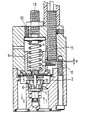
- the only figure shows the pressure control valve in longitudinal section.
- the pressure control valve itself works in a known manner as a P controller.
- the primary pressure occurs at 1.
- an adjusting spring 4 is now tensioned and a diaphragm 5 is pressed downward. It actuates a valve actuation pin 6 and a valve disk 7 lifts off from the valve seat 8.
- the compressed air now flows through the resulting annular gap into secondary pressure chamber 2 and reaches outlet 3 at outlet 3. If no removal takes place, a pressure also builds up in the secondary pressure chamber 2 and pushes the membrane 5 up again.
- valve plate 7 is pressed back onto its seat 8 and the valve closes.
- the pressure in secondary pressure chamber 2 drops, the spring force outweighs the membrane force and the valve opens again.
- valve plate 7 The opening travel of the valve plate 7 is now proportional to the pressure difference ⁇ p between the set secondary pressure and the pressure actually prevailing in the secondary pressure chamber 2. This fact is now used according to the invention for electrical pressure control.
- the adjusting spring 4 acts on the diaphragm 5 via a guide piston 9.
- the guide piston 9 and a pin 10 pressed into it thus make the same path dependent on ⁇ p as the diaphragm 5, the valve actuating pin 6 and the valve plate 7.
Landscapes
- Physics & Mathematics (AREA)
- Fluid Mechanics (AREA)
- General Physics & Mathematics (AREA)
- Engineering & Computer Science (AREA)
- Automation & Control Theory (AREA)
- Control Of Fluid Pressure (AREA)
Claims (4)
Applications Claiming Priority (2)
| Application Number | Priority Date | Filing Date | Title |
|---|---|---|---|
| CH510/83 | 1983-01-28 | ||
| CH51083A CH658503A5 (de) | 1983-01-28 | 1983-01-28 | Druckregelventil mit signalabgabe zwecks sekundaerdruckueberwachung. |
Publications (3)
| Publication Number | Publication Date |
|---|---|
| EP0117844A2 EP0117844A2 (fr) | 1984-09-05 |
| EP0117844A3 EP0117844A3 (en) | 1985-07-24 |
| EP0117844B1 true EP0117844B1 (fr) | 1988-06-15 |
Family
ID=4188658
Family Applications (1)
| Application Number | Title | Priority Date | Filing Date |
|---|---|---|---|
| EP19840810035 Expired EP0117844B1 (fr) | 1983-01-28 | 1984-01-20 | Régulateur de pression avec contrôle électrique |
Country Status (3)
| Country | Link |
|---|---|
| EP (1) | EP0117844B1 (fr) |
| CH (1) | CH658503A5 (fr) |
| DE (1) | DE3472150D1 (fr) |
Families Citing this family (2)
| Publication number | Priority date | Publication date | Assignee | Title |
|---|---|---|---|---|
| DE29801695U1 (de) * | 1998-02-02 | 1998-05-20 | Klamert, Dieter, 87700 Memmingen | Heizkörper-Thermostatventil mit Durchflußanzeige |
| JP3502561B2 (ja) * | 1999-02-22 | 2004-03-02 | Smc株式会社 | レギュレーター |
Family Cites Families (8)
| Publication number | Priority date | Publication date | Assignee | Title |
|---|---|---|---|---|
| DE1640375B1 (de) * | 1967-03-31 | 1972-01-20 | Herion Werke Kg | Elektrischer Stroemungsschalter |
| US3898403A (en) * | 1969-02-03 | 1975-08-05 | Itt | Pressure sensitive control apparatus with magnet actuated switch and valve |
| DE2412054C3 (de) * | 1974-03-11 | 1978-12-21 | Aqua Butzke-Werke Ag, 1000 Berlin | Von der Durchflußmenge unabhängig arbeitende Differenzdruck-Schaltarmatur für flüssige oder gasförmige Medien |
| US3989911A (en) * | 1975-09-05 | 1976-11-02 | Perry Joseph A | Magnetic differential pressure switch |
| US4081621A (en) * | 1976-04-26 | 1978-03-28 | Carr-Griff, Inc. | Pressure switch with diaphragm and valve means |
| US4242082A (en) * | 1978-08-23 | 1980-12-30 | Robertshaw Controls Company | Fluid flow sensing switch device |
| US4317971A (en) * | 1980-05-27 | 1982-03-02 | Rk Industries | Adjustable pressure and vacuum limit switch valve |
| US4423751A (en) * | 1980-12-09 | 1984-01-03 | Cummins Engine Company, Inc. | Bypass valve and alarm assembly |
-
1983
- 1983-01-28 CH CH51083A patent/CH658503A5/de not_active IP Right Cessation
-
1984
- 1984-01-20 EP EP19840810035 patent/EP0117844B1/fr not_active Expired
- 1984-01-20 DE DE8484810035T patent/DE3472150D1/de not_active Expired
Also Published As
| Publication number | Publication date |
|---|---|
| EP0117844A3 (en) | 1985-07-24 |
| CH658503A5 (de) | 1986-11-14 |
| DE3472150D1 (en) | 1988-07-21 |
| EP0117844A2 (fr) | 1984-09-05 |
Similar Documents
| Publication | Publication Date | Title |
|---|---|---|
| DE2748079C2 (de) | Wasserdruck-Verstärkungsanlage | |
| DE2657854A1 (de) | Gasdruckregler | |
| DE102019104067B4 (de) | Elektrisch gesteuertes Proportionalventil mit großer Kapazität | |
| DE2055878A1 (de) | Drucksteuereinnchtung | |
| EP0046166A1 (fr) | Installation de frein à deux conduites réglée en fonction de la charge, pour une remorque | |
| DE1802413A1 (de) | Stroemungsmittel-Steuereinrichtung | |
| EP0117844B1 (fr) | Régulateur de pression avec contrôle électrique | |
| EP0289712B1 (fr) | Régulateur de pression | |
| DE2041766A1 (de) | Druckregler | |
| DE4019757A1 (de) | Membrangesteuerter gasdruckregler | |
| EP0431383B1 (fr) | Soupape antidérapante pour véhicules freinant à air comprimé | |
| DE3828002A1 (de) | Pneumatisch arbeitendes gas-druckregelgeraet | |
| DE10006600B4 (de) | Gasventil und Verfahren zum Betrieb eines Gasventils | |
| DE3607299C2 (fr) | ||
| EP0206132B1 (fr) | Interrupteur commandé en fonction de la pression | |
| AT404065B (de) | Startventil für pneumatische anlagen | |
| EP0546488A2 (fr) | Dispositif de soupape pour l'optimisation de la répartition de l'usure entre les freins des véhicules utilitaires | |
| EP0349751B1 (fr) | Dispositif de freinage d'urgence pour frein à air comprimé à action indirecte | |
| EP0070405A1 (fr) | Accélérateur pour valves-pilotes, particulièrement pour valves pilotes triples de freins à air comprimé pour véhicules ferroviaires | |
| DE3725635C2 (fr) | ||
| EP0215206A1 (fr) | Installation de freinage de conducteur électro-pneumatique pour véhicules ferroviaires | |
| AT233992B (de) | Druckregler mit Sicherheitsventil | |
| EP0026504B1 (fr) | Dispositif modulateur dans un équipement de robinet de frein de mécanicien pour freins à air comprimé à action indirecte de véhicules ferroviaires | |
| DE8619382U1 (de) | Pneumatischer Druckregler für Kraftfahrzeug-Bremsanlagen | |
| DE2719523B2 (de) | Gasventil |
Legal Events
| Date | Code | Title | Description |
|---|---|---|---|
| PUAI | Public reference made under article 153(3) epc to a published international application that has entered the european phase |
Free format text: ORIGINAL CODE: 0009012 |
|
| AK | Designated contracting states |
Designated state(s): DE FR GB IT |
|
| PUAL | Search report despatched |
Free format text: ORIGINAL CODE: 0009013 |
|
| AK | Designated contracting states |
Designated state(s): DE FR GB IT |
|
| 17P | Request for examination filed |
Effective date: 19860116 |
|
| 17Q | First examination report despatched |
Effective date: 19861204 |
|
| GRAA | (expected) grant |
Free format text: ORIGINAL CODE: 0009210 |
|
| AK | Designated contracting states |
Kind code of ref document: B1 Designated state(s): DE FR GB IT |
|
| PG25 | Lapsed in a contracting state [announced via postgrant information from national office to epo] |
Ref country code: IT Free format text: LAPSE BECAUSE OF FAILURE TO SUBMIT A TRANSLATION OF THE DESCRIPTION OR TO PAY THE FEE WITHIN THE PRESCRIBED TIME-LIMIT;WARNING: LAPSES OF ITALIAN PATENTS WITH EFFECTIVE DATE BEFORE 2007 MAY HAVE OCCURRED AT ANY TIME BEFORE 2007. THE CORRECT EFFECTIVE DATE MAY BE DIFFERENT FROM THE ONE RECORDED. Effective date: 19880615 |
|
| REF | Corresponds to: |
Ref document number: 3472150 Country of ref document: DE Date of ref document: 19880721 |
|
| ET | Fr: translation filed | ||
| GBT | Gb: translation of ep patent filed (gb section 77(6)(a)/1977) | ||
| PLBE | No opposition filed within time limit |
Free format text: ORIGINAL CODE: 0009261 |
|
| STAA | Information on the status of an ep patent application or granted ep patent |
Free format text: STATUS: NO OPPOSITION FILED WITHIN TIME LIMIT |
|
| 26N | No opposition filed | ||
| ITTA | It: last paid annual fee | ||
| PGFP | Annual fee paid to national office [announced via postgrant information from national office to epo] |
Ref country code: FR Payment date: 19951207 Year of fee payment: 13 |
|
| PGFP | Annual fee paid to national office [announced via postgrant information from national office to epo] |
Ref country code: GB Payment date: 19951219 Year of fee payment: 13 |
|
| PGFP | Annual fee paid to national office [announced via postgrant information from national office to epo] |
Ref country code: DE Payment date: 19951220 Year of fee payment: 13 |
|
| PG25 | Lapsed in a contracting state [announced via postgrant information from national office to epo] |
Ref country code: GB Effective date: 19970120 |
|
| GBPC | Gb: european patent ceased through non-payment of renewal fee |
Effective date: 19970120 |
|
| PG25 | Lapsed in a contracting state [announced via postgrant information from national office to epo] |
Ref country code: FR Effective date: 19970930 |
|
| PG25 | Lapsed in a contracting state [announced via postgrant information from national office to epo] |
Ref country code: DE Effective date: 19971001 |
|
| REG | Reference to a national code |
Ref country code: FR Ref legal event code: ST |