EP0118049A1 - Régulateur de débit de liquide - Google Patents
Régulateur de débit de liquide Download PDFInfo
- Publication number
- EP0118049A1 EP0118049A1 EP19840101252 EP84101252A EP0118049A1 EP 0118049 A1 EP0118049 A1 EP 0118049A1 EP 19840101252 EP19840101252 EP 19840101252 EP 84101252 A EP84101252 A EP 84101252A EP 0118049 A1 EP0118049 A1 EP 0118049A1
- Authority
- EP
- European Patent Office
- Prior art keywords
- valve body
- casing
- liquid
- sliding projections
- port
- Prior art date
- Legal status (The legal status is an assumption and is not a legal conclusion. Google has not performed a legal analysis and makes no representation as to the accuracy of the status listed.)
- Granted
Links
- 239000007788 liquid Substances 0.000 title claims abstract description 93
- 239000002245 particle Substances 0.000 claims abstract description 15
- 239000007787 solid Substances 0.000 claims abstract description 11
- 238000011144 upstream manufacturing Methods 0.000 claims description 15
- 230000002093 peripheral effect Effects 0.000 claims description 10
- 235000015192 vegetable juice Nutrition 0.000 claims description 6
- 235000021022 fresh fruits Nutrition 0.000 claims description 4
- 238000010276 construction Methods 0.000 abstract description 2
- 238000000034 method Methods 0.000 description 6
- 235000015203 fruit juice Nutrition 0.000 description 2
- 235000011389 fruit/vegetable juice Nutrition 0.000 description 2
- 238000004519 manufacturing process Methods 0.000 description 2
- 235000020357 syrup Nutrition 0.000 description 2
- 239000006188 syrup Substances 0.000 description 2
- 238000007599 discharging Methods 0.000 description 1
- 235000013399 edible fruits Nutrition 0.000 description 1
- 235000013311 vegetables Nutrition 0.000 description 1
Images

Classifications
-
- B—PERFORMING OPERATIONS; TRANSPORTING
- B67—OPENING, CLOSING OR CLEANING BOTTLES, JARS OR SIMILAR CONTAINERS; LIQUID HANDLING
- B67D—DISPENSING, DELIVERING OR TRANSFERRING LIQUIDS, NOT OTHERWISE PROVIDED FOR
- B67D1/00—Apparatus or devices for dispensing beverages on draught
- B67D1/08—Details
- B67D1/12—Flow or pressure control devices or systems, e.g. valves, gas pressure control, level control in storage containers
-
- G—PHYSICS
- G05—CONTROLLING; REGULATING
- G05D—SYSTEMS FOR CONTROLLING OR REGULATING NON-ELECTRIC VARIABLES
- G05D7/00—Control of flow
- G05D7/01—Control of flow without auxiliary power
- G05D7/0126—Control of flow without auxiliary power the sensing element being a piston or plunger associated with one or more springs
- G05D7/0133—Control of flow without auxiliary power the sensing element being a piston or plunger associated with one or more springs within the flow-path
-
- Y—GENERAL TAGGING OF NEW TECHNOLOGICAL DEVELOPMENTS; GENERAL TAGGING OF CROSS-SECTIONAL TECHNOLOGIES SPANNING OVER SEVERAL SECTIONS OF THE IPC; TECHNICAL SUBJECTS COVERED BY FORMER USPC CROSS-REFERENCE ART COLLECTIONS [XRACs] AND DIGESTS
- Y10—TECHNICAL SUBJECTS COVERED BY FORMER USPC
- Y10T—TECHNICAL SUBJECTS COVERED BY FORMER US CLASSIFICATION
- Y10T137/00—Fluid handling
- Y10T137/7722—Line condition change responsive valves
- Y10T137/7781—With separate connected fluid reactor surface
- Y10T137/7784—Responsive to change in rate of fluid flow
- Y10T137/7792—Movable deflector or choke
Definitions
- This invention relates to a liquid flow rate controller for controlling the flow rate of a liquid such as syrup or fruit or vegetable juice in which a great number of small solid particles are mixed.
- fresh syrup or fruit or vegetable juice often has numerous small particles of fruit or vegetable therein.
- a liquid is stored in a pressure tank which is under pressure provided by a compressed gas.
- a discharge pipe is connected to the tank in order to feed the liquid to a cup for a customer through a valve or cock provided at the downstream end of the pipe.
- a flow rate controller or regulator is provided midway in the pipe line so that the liquid can flow at a constant pressure through the pipe.
- a conventional flow controller for such use has a cylindrical casing in which a piston-like valve body is slidably accommodated.
- the valve body is in the shape of a cup and has an orifice at its end face facing the inlet of the casing.
- the valve body is urged by a coil spring toward the inlet of the casing. That is, the liquid passing through the inlet pushes the end face of the valve body toward the downstream side while compressing the coil spring.
- At least one outlet which is opened and closed by the downstream end of the side wall of the valve body.
- valve body When the pressure of inflow liquid is higher than normal, the valve body is so moved as to close the outlet because the pressure of liquid which has entered the valve body through the orifice of the end face thereof is lower than that of liquid in the vicinity of the inlet.
- the liquid pressure in the valve body becomes high thereby to cause the valve body to return toward the upstream side by the returning force of the coil spring. That is, the valve body is moved in the casing according to the difference in pressure between the inflow and outflow liquids to keep the flow rate of the outflow liquid constant.
- a liquid flow controller for controlling the outflow rate of a liquid containing a large number of solid particles such as fresh fruit or vegetable juice or the like in which a valve body is slidably accommodated in a casing having at least one liquid inflow opening and at least one liquid outflow opening, one end of the valve body being closed by an end plate having an orifice while the other end thereof is open, said valve body being urged upstream by an elastic member, between the casing and the side wall of the valve body being formed a port means for adjusting the outflow rate of the liquid flowing therethrough in a manner that said valve body is moved in the casing in response to change of the liquid pressure therein thereby to open and close the port means, characterized in that a wide space is provided between the outer peripheral surface of the valve body and the inner surface of the casing by the forming of a plurality of sliding projections, between the casing and the valve body, a flexible closing member being provided or preventing the inflow liquid from passing through the space to directly reach the
- liquid flow controller for controlling the outflow rate of a liquid containing numerous solid particles such as fresh fruit or vegetable juice or the like in which a valve body is slidably accommodated in a casing having at least one liquid inflow opening and at least one liquid outflow opening, one end of the valve body being closed by an end plate having an orifice while the other end thereof is open, said valve body being urged upstream by an elastic member, between the casing and the side wall of the valve body being formed a port means for adjusting the outflow rate of the liquid flowing through the outflow opening in a manner such that said valve body is moved in the casing in response to change of the liquid pressure therein to open and close the port means, characterized in that said casing has an expanded portion of an annular shape in which said liquid inflow opening is provided, a plurality of sliding projections being formed either on the peripheral surface of the valve body or the inner surface of the casing for forming a wide space between the valve body and the casing, at least one port being provided on
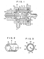
- FIG. 1 shows a side elevation in vertical section of a first example of a liquid flow rate controller or regulator.
- the controller has a cylindrical outer casing 10 which comprises a main body 10a and a coaxial root portion 10b having a smaller diameter than that of the main body 10a.
- the side wall of the main body 10a is provided with an outlet 11 for discharging liquid, and the inlet end or right end of the main body 10a as viewed in FIG. 1 is closed by a cap 12, forming a part of the outer casing 10, which has an inlet 12a for leading the liquid into the controller.
- the outlet 11 and the inlet 12a are respectively connected to two tubes (not shown) for feeding the liquid to be adjusted or controlled.
- a cylindrical inner casing 13 In the main body 10a is coaxially accommodated a cylindrical inner casing 13 in such a manner that a cylindrical space S1 is formed between the inner surface of the main body and the outer surface of the inner casing 13.
- the left end of the inner casing 13 is fixed to the inner vertical wall of the main body 10a, and the right end of the inner casing 13 has a flange 13a which is engaged with a shoulder 10c which is formed in the right end of the main body 10a.
- a seal ring 14a which is formed along the outer periphery of an elastic diaphragm 14 made of rubber or the like.
- This diaphragm 14, the outer periphery of the cap 12 and the flange 13a of the inner casing 13 are fixed to the right end of the main body by a fastening nut 15 in screw engagement with the outer periphery of the inlet or upstream end of the main body 10a.
- valve body 16 which is in the shape of a cup.
- the valve body 16 at its right end has an end plate 16a which is provided with an orifice 17 in the center thereof.
- the details of the valve body 16 are shown in FIGS. 2 and 3.
- On the outer peripheries of the opposite ends of the valve body 16 are formed a plurality of sliding projections 18, at equal space intervals in its circumferential direction, respectively, which contact slidably the inner surface of the inner casing 13 with an ample space S 2 formed between the outer peripheral surface of the side wall of the valve body 16 and the inner cylindrical surface of the inner casing 13.
- the valve body 16 is urged by a coil spring 19 toward the inlet 12a or the upstream side, and on the right or front face of the end plate 16a thereof is formed a fastening portion 20 for fastening an inner rim of a central hole of the diaphragm 14.
- the valve body 16 is held by the diaphragm 14 in a manner permitting the valve body 16 to move in the left-right directions as viewed in FIG. 1 but not permitting rotation thereof about its axis.
- the inner casing 13 has a plurality of outlet ports 13b formed near the left end of its cylindrical wall in their respective angular positions corresponding to the sliding projections 18 of the valve body 16 as shown in FIG. 3, so that the ports 13b can be opened and closed by the sliding projections 18 according to the lateral movement of the valve body 16.
- a holding member 21 for holding an adjusting needle 22 whose free and tapered end 22a is adjustably inserted in the orifice 17 for adjusting the opening size of the orifice 17.
- the holding member 21 has a male-screw portion 21a which is engaged with the female-screw portion 10d of the root portion 10b so that the needle 22 can move in the longitudinal direction.
- the liquid containing numerous solid particles flows into the controller through the inlet 12a of the cap 12 and then enters the valve body 16 through the orifice 17. Thereafter, the liquid in the valve body 16 flows into the spaces through the ports 13b formed in the cylindrical wall of the inner casing 13, and is then discharged through the outlet 11 of the outer casing 10.
- the valve body 16 When the liquid pressure on the upstream side of the valve'body 16 is relatively low, the valve body 16 is placed in a position where the ports 13b are fully opened as shown in FIG. 1. However, when the liquid pressure on the upstream side of the body 16 becomes high thereby to increase the pressure difference between the upstream and downstream sides of the valve body 16, the valve body 16 is moved in the leftward direction as viewed in FIG. 1 whereby the ports 13b are gradually closed respectively by the sliding projections 18. This results in an increase of the liquid pressure on the side of the ports 13b to cause the valve body 16 to move in the rightward direction under the returning force of the coil spring 19. Thus, the ports 13b are gradually opened, so that the amount of the outflow liquid gradually increases.
- the liquid pressure on the side of the ports 13b is lower than that on the side of the inlet 12a because the inflow liquid passes restrictively through the orifice 17 of the end plate 16a. Accordingly, if the coil spring 19 were not used, the valve body 16 would move in the leftward direction even when the liquid pressure on the side of the inlet 12a is very low.
- the total of the force due to the liquid pressure on the side of the ports 13b in the inner casing 13 and the returning force of the coil spring 19 is a combined force component tending to move the valve body 16 in the upstream direction, while the liquid pressure on the inlet 12a results in a force component urging the valve body 16 to move in the downstream direction.
- valve body 16 moves in the leftward or downstream direction. Conversely, when the force due to the liquid pressure on the inlet side becomes less than the rightward total force, the valve body 16 moves in the rightward or upstream direction. As a result, the valve body 16 assumes a standstill state of equilibrium in a position where the rightward total force is equal to the leftward force due to the liquid pressure on the inlet side. In this manner, the flow rate of the liquid discharged out of the outlet 11 is kept constant as indicated in FIG. 4.
- the ordinate indicates the flow rate of the outflow liquid
- the abscissa indicates the pressure difference between the inlet 12a and the outlet 11.
- the flow rate of the outflow liquid can be kept constant as indicated by the curved line C after the pressure difference exceeds a specific value because of the existence of the coil spring 19.
- the adjusting needle 22 is not absolutely necessary in the controller in all cases. However, if the orifice 17 is narrowed or widened by moving the needle 22 in its axial direction, the flow rate of the outflow liquid can be adjusted in a very wide range.
- the diaphragm 14 functions to prevent the inflow liquid from flowing from the upstream side of the valve body 16 into the space 5 2 . Even if some of the outflow liquid were to flow from the downstream side of the valve body 16 into the space S 2 , the valve body 16 can move smoothly in its axial direction at all times because the space S 2 is wide enough to prevent the solid particles in the liquid from jamming in or clogging the space 5 2 .
- FIG. 5 shows a second example of this invention.
- bellows 23 are used instead of the diaphragm 14 in order to close the upstream end of the space S 2 .
- any member for closing the upstream end of the space S 2 can be used if it is flexible enough to permit the valve body 16 to move smoothly in the inner casing 13.
- a cylindrical inner casing 30 has an annular groove 31a on its inner surface and a plurality of connecting holes 31b for connecting the groove 31a to the outside of the inner casing 30.
- a valve body 32 slidably accommodated within the inner casing 30 has a plurality of sliding projections 33 similar to the sliding projections 18 as described in the first example.
- a port 34 for connecting the groove 31a to the inside of the valve body 32.
- Each port 34 is opened and closed according to the movement of the valve body 32.
- annular groove 31a facilitates the assembly of the valve body 32 and the inner casing 30 because it is not necessary that each hole 34 be precisely registered with a respective hole 31b in their angular positions about the axis of the valve body 32 when the valve body 32 is inserted into the inner casing 30.
- a thin and flexible diaphragm 35 may be provided in the space S 2 .
- the sliding projections 18, 33 are formed on the valve bodies 16, 32, respectively.
- a valve body In general, a valve body must be smoothly movable in an inner casing in order to accurately adjust the flow rate of a liquid to be controlled.
- the peripheral surfaces of the valve body and the inner casing are precisely finished by respectively different grinding machines.
- the inner surface of the inner casing is usually finished by a honing process and the outer surface of the valve body is usually finished by a centerless grinding process. In the case of the centerless grinding process, if the sliding projections are formed on the peripheral surface of the valve body, the process cannot be carried out.
- FIG. 7 shows a fourth example in which a plurality of sliding projections 41 are formed on the inner cylindrical surface of an inner casing 40, and the smooth outer cylindrical surface of a valve body 42 is slidably engaged with the sliding projections 41.
- the sliding projections 41 are annularly disposed on the inner surface of the inner casing 40 at spaced- apart positions.
- the inner casing 40 has a plurality of ports 43 which are respectively provided in respective positions where the sliding projections 41 are formed. Each port 43 is opened and closed by the downstream end portion of the valve body 42.
- each sliding projection 51 is respectively formed inside of the opposite ends of the inner casing 40.
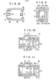
- each sliding projection 51 may be formed in a manner such that the outer ends of the respective projections 51 extend to the opposite extreme ends of a valve body 50, respectively, as shown in FIG. 8.
- a port 52 is formed in each projection 51 on the downstream side of the valve body 50.
- two annular sliding projections 63a, 63b are formed, with a specific spacing therebetween, on the inner surface of an inner casing 62 with an annular groove 64 formed therebetween.
- a plurality of connecting holes 65 for connecting the groove 64 to the outside of the inner casing 62.
- a plurality of ports 61 for connecting the groove 64 to the interior of the valve body 60.
- the ports and holes 61, 65 and the groove 64 form an outlet port means.
- Each port 61 is opened and closed by either the projection 63a or 63b according to the movement of the valve body 60.
- valve body 60 is smooth, without projections, and the groove 64 is provided between the ports 61 and holes 65. Accordingly, the valve body 60 can be finished by the centerless grinding method and registration between the ports and holes 61 and 65 is not necessary.
- a cylindrical casing 70 has an annular diametrically expanded portion 71 which is provided with an inlet 72.
- valve body 73 having three groups of sliding projections 80a, 80b and 80c.
- the projections 80b have respective ports 74.
- the right end face of the valve body 73 is closed except for a central orifice 75, while the opposite end thereof is open.
- the valve body 73 is urged by a coil spring 77 to move in the leftward direction as viewed in FIG. 10.
- a space S 2 between the outer peripheral surface of the valve body and the inner cylindrical surface of the casing 70 is closed by two respective diaphragms 78 and 79 at its opposite ends.
- the liquid flows as indicated by arrow marks and is discharged through an outlet 76 formed in the casing 70.
- the ports 74 are opened and closed by the wall portion 70a of the casing 70, whereby the outflow rate can be kept constant.
- FIG. 11 shows a seventh example of this invention similar to that of FIG. 10.
- a valve body 90 has a flat side cylindrical outer wall of smooth outer surface in which a plurality of ports 91 are provided.
- a casing 92 for accommodating the valve body 90 has three groups of sliding projections 93a, 93b and 93c. The sliding projections 93b open and close respective ports 91 to keep the outflow rate constant.
Landscapes
- Physics & Mathematics (AREA)
- General Physics & Mathematics (AREA)
- Engineering & Computer Science (AREA)
- Automation & Control Theory (AREA)
- Safety Valves (AREA)
- Flow Control (AREA)
- Devices For Dispensing Beverages (AREA)
- Loading And Unloading Of Fuel Tanks Or Ships (AREA)
Applications Claiming Priority (2)
| Application Number | Priority Date | Filing Date | Title |
|---|---|---|---|
| JP1983017636U JPS59126899U (ja) | 1983-02-09 | 1983-02-09 | 流量調整装置 |
| JP17636/83U | 1983-02-09 |
Publications (2)
| Publication Number | Publication Date |
|---|---|
| EP0118049A1 true EP0118049A1 (fr) | 1984-09-12 |
| EP0118049B1 EP0118049B1 (fr) | 1989-01-04 |
Family
ID=11949349
Family Applications (1)
| Application Number | Title | Priority Date | Filing Date |
|---|---|---|---|
| EP19840101252 Expired EP0118049B1 (fr) | 1983-02-09 | 1984-02-08 | Régulateur de débit de liquide |
Country Status (6)
| Country | Link |
|---|---|
| US (1) | US4648424A (fr) |
| EP (1) | EP0118049B1 (fr) |
| JP (1) | JPS59126899U (fr) |
| AU (1) | AU570427B2 (fr) |
| CA (1) | CA1224446A (fr) |
| DE (1) | DE3475972D1 (fr) |
Cited By (4)
| Publication number | Priority date | Publication date | Assignee | Title |
|---|---|---|---|---|
| GB2175980A (en) * | 1985-05-23 | 1986-12-10 | Moteurs Societe Nationale D Et | Pressure reducer |
| FR2583495A1 (fr) * | 1985-06-13 | 1986-12-19 | Cobe Lab | Dispositif de regulation de debit perfectionne, a pression differentielle |
| GB2202611A (en) * | 1987-03-13 | 1988-09-28 | Secr Defence | Flow control device |
| GB2320955A (en) * | 1997-01-03 | 1998-07-08 | Hobourn Automotive Ltd | Flow control valve |
Families Citing this family (17)
| Publication number | Priority date | Publication date | Assignee | Title |
|---|---|---|---|---|
| US4867198A (en) * | 1988-10-11 | 1989-09-19 | Faust Bobby G | Adjustable flow regulating valve |
| US5127431A (en) * | 1991-05-08 | 1992-07-07 | The Coca-Cola Company | Flow control system for a beverage dispenser |
| IL98266A (en) * | 1991-05-26 | 1994-08-26 | Feldman Joseph | Dosage valve extract for use in systems for making carbonated sweetened beverages |
| US5205320A (en) * | 1991-07-17 | 1993-04-27 | Kyocera Corporation | Flow rate control unit |
| US5251655A (en) * | 1992-07-06 | 1993-10-12 | Wilshire Partners | Flow control valves for post-mix beverage dispensers |
| JPH0712254A (ja) * | 1993-06-22 | 1995-01-17 | Sumitomo Electric Ind Ltd | 流量制御弁 |
| DE4412459C2 (de) * | 1994-04-08 | 1997-01-23 | Luk Fahrzeug Hydraulik | Ventilanordnung |
| DE4412461C2 (de) * | 1994-04-08 | 1997-01-30 | Luk Fahrzeug Hydraulik | Ventilanordnung |
| US5427139A (en) * | 1994-05-06 | 1995-06-27 | A & H Enterprises, Inc. | Metering valve with adjustable floating piston and pin assembly |
| DE4445589C2 (de) * | 1994-12-20 | 1997-12-18 | Danfoss As | Membrangesteuertes Ventil zur Aufrechterhaltung eines Differenzdrucks |
| ATE364149T1 (de) * | 2001-10-25 | 2007-06-15 | Frese As | Differenzialdruckventil |
| GB2381568A (en) * | 2001-10-31 | 2003-05-07 | Fluid Controls U K Ltd | Flow control valve |
| US20050076951A1 (en) * | 2003-10-06 | 2005-04-14 | Gray John M. | Pressure actuated valve |
| US7464722B2 (en) * | 2005-08-05 | 2008-12-16 | Jansen's Aircraft Systems Controls, Inc. | Fluid proportioning valve |
| US8210200B2 (en) * | 2007-12-17 | 2012-07-03 | Flsmidth A/S | Flow regulator device |
| JP2008224040A (ja) * | 2008-04-17 | 2008-09-25 | Kawasaki Precision Machinery Ltd | 過流防止弁装置 |
| US9933792B2 (en) * | 2015-03-23 | 2018-04-03 | Lancer Corporation | Method and apparatus for flow regulation |
Citations (4)
| Publication number | Priority date | Publication date | Assignee | Title |
|---|---|---|---|---|
| FR50330E (fr) * | 1939-04-04 | 1940-03-16 | Régulateur de débit de fluides | |
| US3805824A (en) * | 1972-09-25 | 1974-04-23 | Us Navy | Pressure-compensated flow control valve |
| US3948419A (en) * | 1974-08-01 | 1976-04-06 | Concession Service Corporation | Beverage fluid flow controller |
| FR2339203A1 (fr) * | 1976-01-20 | 1977-08-19 | Bronzavia Sa | Dispositif de reglage de la pression differentielle entre deux points de pressions differentes d'un circuit de fluide |
Family Cites Families (13)
| Publication number | Priority date | Publication date | Assignee | Title |
|---|---|---|---|---|
| US2198487A (en) * | 1936-12-22 | 1940-04-23 | Martin A Sisk | Automatic valve |
| US2584418A (en) * | 1948-04-19 | 1952-02-05 | Robertshaw Fulton Controls Co | Constant flow valve |
| US2960109A (en) * | 1957-01-07 | 1960-11-15 | Gen Controls Co | Flow regulator |
| US3120243A (en) * | 1962-02-05 | 1964-02-04 | Fawick Corp | Flow regulating valve with extended movement |
| US3219325A (en) * | 1962-12-04 | 1965-11-23 | Brown William | Mixing valve |
| US3292656A (en) * | 1965-10-19 | 1966-12-20 | Acf Ind Inc | Crankcase ventilator valve |
| US3464439A (en) * | 1966-06-16 | 1969-09-02 | Weatherhead Co | Flow control valve |
| US3422842A (en) * | 1966-11-16 | 1969-01-21 | Dole Valve Co | Adjustable flow control |
| JPS5130655Y2 (fr) * | 1971-03-04 | 1976-08-02 | ||
| JPS4969121U (fr) * | 1972-09-27 | 1974-06-17 | ||
| JPS54109926U (fr) * | 1978-01-20 | 1979-08-02 | ||
| JPS5551174A (en) * | 1978-10-04 | 1980-04-14 | Hidekuni Yokota | Variable, fixed flow-rate valve device |
| DE2852935C2 (de) * | 1978-12-07 | 1982-12-23 | Hansa Metallwerke Ag, 7000 Stuttgart | Thermostatventil |
-
1983
- 1983-02-09 JP JP1983017636U patent/JPS59126899U/ja active Granted
-
1984
- 1984-02-01 US US06/575,814 patent/US4648424A/en not_active Expired - Lifetime
- 1984-02-07 AU AU24243/84A patent/AU570427B2/en not_active Ceased
- 1984-02-08 DE DE8484101252T patent/DE3475972D1/de not_active Expired
- 1984-02-08 CA CA000446964A patent/CA1224446A/fr not_active Expired
- 1984-02-08 EP EP19840101252 patent/EP0118049B1/fr not_active Expired
Patent Citations (4)
| Publication number | Priority date | Publication date | Assignee | Title |
|---|---|---|---|---|
| FR50330E (fr) * | 1939-04-04 | 1940-03-16 | Régulateur de débit de fluides | |
| US3805824A (en) * | 1972-09-25 | 1974-04-23 | Us Navy | Pressure-compensated flow control valve |
| US3948419A (en) * | 1974-08-01 | 1976-04-06 | Concession Service Corporation | Beverage fluid flow controller |
| FR2339203A1 (fr) * | 1976-01-20 | 1977-08-19 | Bronzavia Sa | Dispositif de reglage de la pression differentielle entre deux points de pressions differentes d'un circuit de fluide |
Cited By (7)
| Publication number | Priority date | Publication date | Assignee | Title |
|---|---|---|---|---|
| GB2175980A (en) * | 1985-05-23 | 1986-12-10 | Moteurs Societe Nationale D Et | Pressure reducer |
| FR2583495A1 (fr) * | 1985-06-13 | 1986-12-19 | Cobe Lab | Dispositif de regulation de debit perfectionne, a pression differentielle |
| GB2202611A (en) * | 1987-03-13 | 1988-09-28 | Secr Defence | Flow control device |
| GB2202611B (en) * | 1987-03-13 | 1991-05-15 | Secr Defence | Flow control device |
| GB2320955A (en) * | 1997-01-03 | 1998-07-08 | Hobourn Automotive Ltd | Flow control valve |
| GB2320955B (en) * | 1997-01-03 | 1999-08-04 | Hobourn Automotive Ltd | Flow control valve |
| US6328535B1 (en) | 1997-01-03 | 2001-12-11 | Hobourn Automative Limited | Flow control valve capable of adjusting fluid flow characteristics in accordance with a position of a valve element in a bore |
Also Published As
| Publication number | Publication date |
|---|---|
| AU570427B2 (en) | 1988-03-17 |
| DE3475972D1 (en) | 1989-02-09 |
| EP0118049B1 (fr) | 1989-01-04 |
| CA1224446A (fr) | 1987-07-21 |
| AU2424384A (en) | 1984-08-16 |
| JPH0310444Y2 (fr) | 1991-03-14 |
| US4648424A (en) | 1987-03-10 |
| JPS59126899U (ja) | 1984-08-27 |
Similar Documents
| Publication | Publication Date | Title |
|---|---|---|
| US4648424A (en) | Liquid flow rate controller | |
| US4730635A (en) | Valve and method | |
| US4295631A (en) | Solenoid operated valve | |
| US5462081A (en) | Excess flow valve | |
| US6026849A (en) | High pressure regulated flow controller | |
| US4074693A (en) | Readily disassembleable fluid flow rate controller | |
| US5383646A (en) | Diaphragm control valve | |
| US3703913A (en) | Automatic rate of flow control valve | |
| MXPA04001970A (es) | Valvula de control de flujo. | |
| SE469572B (sv) | Ventil vid tryckspridarmunstycke | |
| US10379549B2 (en) | Pressure independent control valve | |
| EP0224584B1 (fr) | Cartouche regulatrice d'ecoulement par restriction a pression compensee | |
| WO1998051948A1 (fr) | Soupape d'excedent de debit a corps a ressort et son procede d'utilisation | |
| US3762681A (en) | Fluid flow control device with baffles | |
| US5097863A (en) | Flow control apparatus | |
| US4887639A (en) | Non-degrading pressure regulator | |
| US4237922A (en) | In-line flow control valve | |
| US4171006A (en) | Fluid metering valve | |
| EP0596116A1 (fr) | Valve de regulation | |
| US2888237A (en) | Constant rate of flow shut-off valve | |
| US4815497A (en) | Valve assembly and flow control therefor | |
| US5127431A (en) | Flow control system for a beverage dispenser | |
| US4549572A (en) | Pressure compensated fluid flow regulator | |
| US4381797A (en) | Flow control valve with a non-rising stem | |
| US4324269A (en) | Pressure regulator |
Legal Events
| Date | Code | Title | Description |
|---|---|---|---|
| PUAI | Public reference made under article 153(3) epc to a published international application that has entered the european phase |
Free format text: ORIGINAL CODE: 0009012 |
|
| AK | Designated contracting states |
Designated state(s): CH DE FR GB LI NL SE |
|
| 17P | Request for examination filed |
Effective date: 19841106 |
|
| 17Q | First examination report despatched |
Effective date: 19860917 |
|
| GRAA | (expected) grant |
Free format text: ORIGINAL CODE: 0009210 |
|
| AK | Designated contracting states |
Kind code of ref document: B1 Designated state(s): CH DE FR GB LI NL SE |
|
| REF | Corresponds to: |
Ref document number: 3475972 Country of ref document: DE Date of ref document: 19890209 |
|
| ET | Fr: translation filed | ||
| PLBE | No opposition filed within time limit |
Free format text: ORIGINAL CODE: 0009261 |
|
| STAA | Information on the status of an ep patent application or granted ep patent |
Free format text: STATUS: NO OPPOSITION FILED WITHIN TIME LIMIT |
|
| 26N | No opposition filed | ||
| REG | Reference to a national code |
Ref country code: CH Ref legal event code: PUE Owner name: KIRIN BEVERAGE CORPORATION |
|
| REG | Reference to a national code |
Ref country code: GB Ref legal event code: 732 |
|
| REG | Reference to a national code |
Ref country code: FR Ref legal event code: TP |
|
| NLS | Nl: assignments of ep-patents |
Owner name: KIRIN BEVERAGE CORPORATION TE TOKIO, JAPAN. |
|
| EAL | Se: european patent in force in sweden |
Ref document number: 84101252.9 |
|
| PGFP | Annual fee paid to national office [announced via postgrant information from national office to epo] |
Ref country code: GB Payment date: 19950131 Year of fee payment: 12 |
|
| PGFP | Annual fee paid to national office [announced via postgrant information from national office to epo] |
Ref country code: FR Payment date: 19950210 Year of fee payment: 12 |
|
| PGFP | Annual fee paid to national office [announced via postgrant information from national office to epo] |
Ref country code: SE Payment date: 19950216 Year of fee payment: 12 |
|
| PGFP | Annual fee paid to national office [announced via postgrant information from national office to epo] |
Ref country code: NL Payment date: 19950228 Year of fee payment: 12 |
|
| PG25 | Lapsed in a contracting state [announced via postgrant information from national office to epo] |
Ref country code: GB Effective date: 19960208 |
|
| PG25 | Lapsed in a contracting state [announced via postgrant information from national office to epo] |
Ref country code: SE Effective date: 19960209 |
|
| PG25 | Lapsed in a contracting state [announced via postgrant information from national office to epo] |
Ref country code: NL Effective date: 19960901 |
|
| GBPC | Gb: european patent ceased through non-payment of renewal fee |
Effective date: 19960208 |
|
| PG25 | Lapsed in a contracting state [announced via postgrant information from national office to epo] |
Ref country code: FR Effective date: 19961031 |
|
| NLV4 | Nl: lapsed or anulled due to non-payment of the annual fee |
Effective date: 19960901 |
|
| REG | Reference to a national code |
Ref country code: FR Ref legal event code: ST |
|
| PGFP | Annual fee paid to national office [announced via postgrant information from national office to epo] |
Ref country code: DE Payment date: 19990427 Year of fee payment: 16 |
|
| PGFP | Annual fee paid to national office [announced via postgrant information from national office to epo] |
Ref country code: CH Payment date: 19990527 Year of fee payment: 16 |
|
| PG25 | Lapsed in a contracting state [announced via postgrant information from national office to epo] |
Ref country code: LI Free format text: LAPSE BECAUSE OF NON-PAYMENT OF DUE FEES Effective date: 20000229 Ref country code: CH Free format text: LAPSE BECAUSE OF NON-PAYMENT OF DUE FEES Effective date: 20000229 |
|
| REG | Reference to a national code |
Ref country code: CH Ref legal event code: PL |
|
| PG25 | Lapsed in a contracting state [announced via postgrant information from national office to epo] |
Ref country code: DE Free format text: LAPSE BECAUSE OF NON-PAYMENT OF DUE FEES Effective date: 20001201 |