EP0118077A2 - Butée à onglets - Google Patents
Butée à onglets Download PDFInfo
- Publication number
- EP0118077A2 EP0118077A2 EP84101782A EP84101782A EP0118077A2 EP 0118077 A2 EP0118077 A2 EP 0118077A2 EP 84101782 A EP84101782 A EP 84101782A EP 84101782 A EP84101782 A EP 84101782A EP 0118077 A2 EP0118077 A2 EP 0118077A2
- Authority
- EP
- European Patent Office
- Prior art keywords
- index
- rail
- stop
- workpiece
- workpiece holder
- Prior art date
- Legal status (The legal status is an assumption and is not a legal conclusion. Google has not performed a legal analysis and makes no representation as to the accuracy of the status listed.)
- Granted
Links
Images
Classifications
-
- B—PERFORMING OPERATIONS; TRANSPORTING
- B27—WORKING OR PRESERVING WOOD OR SIMILAR MATERIAL; NAILING OR STAPLING MACHINES IN GENERAL
- B27B—SAWS FOR WOOD OR SIMILAR MATERIAL; COMPONENTS OR ACCESSORIES THEREFOR
- B27B25/00—Feeding devices for timber in saw mills or sawing machines; Feeding devices for trees
- B27B25/10—Manually-operated feeding or pressing accessories, e.g. pushers
-
- B—PERFORMING OPERATIONS; TRANSPORTING
- B27—WORKING OR PRESERVING WOOD OR SIMILAR MATERIAL; NAILING OR STAPLING MACHINES IN GENERAL
- B27G—ACCESSORY MACHINES OR APPARATUS FOR WORKING WOOD OR SIMILAR MATERIALS; TOOLS FOR WORKING WOOD OR SIMILAR MATERIALS; SAFETY DEVICES FOR WOOD WORKING MACHINES OR TOOLS
- B27G5/00—Machines or devices for working mitre joints with even abutting ends
- B27G5/02—Machines or devices for working mitre joints with even abutting ends for sawing mitre joints; Mitre boxes
- B27G5/023—Machines or devices for working mitre joints with even abutting ends for sawing mitre joints; Mitre boxes the mitre angle being adjusted by positioning a workpiece relative to a fixed saw
Definitions
- the workpiece stop is indeed provided with a rear projection which has a slot guide for a clamping screw which can be tightened by means of a nut and which is provided with a through hole for inserting the index pin.
- This arrangement which serves to enable the setting of intermediate angles by moving the clamping screw within the associated slot guide, also allowed an adjustment of the stop edge of the workpiece stop with respect to a reference line, e.g. B. with respect to the working plane of the cutting tool.
- a reference line e.g. B.
- the workpiece stop has an index rail which is pivotably mounted on the workpiece holder about the axis perpendicular to the support surface of the workpiece holder and has an exact fit for the index pin and an index rail on the latter with a degree of freedom of rotation relative to the index pin by a bearing surface of the workpiece holder vertical axis has pivotally mounted stop rail, the pivoting position of which can be adjusted relative to the index rail by means of an adjusting device.
- the arrangement according to the invention is therefore based on a two-part workpiece stop.
- the two-part design of the workpiece stop advantageously enables an exact adjustment of the stop rail which can be pivoted with respect to the index rail and has a stop edge with respect to a reference line, for example with an index rail fixed by the index pin. B. with respect to the feed direction or the adjacent side of the machine table or the working plane of the cutting tool.
- Such an adjustability is advantageous when installing for the first time, since manufacturing and assembly tolerances cannot be eliminated and the installation site generally differs from the assembly site in terms of local conditions.
- the Position of the index rail remains advantageously fixed during the adjustment of the stop rail relative to the workpiece holder, it is also ensured that in the case of a scale associated with the index rail, provided with an angular division, despite a possible shift in the angular position of the stop rail, no change in the position of the scale assigned reading edge of the index rail results, which has a positive effect on the achievable setting accuracy and ease of use. From this it can be seen that the invention solves the task set with simple and therefore inexpensive means.
- index rail and the adjusting rail mounted thereon have a common pivot axis.
- the index rail can expediently have a U-shaped cross section which is open towards the stop rail, the stop rail being able to engage between the legs of the U rail forming the index rail, which results in a wobble-proof reception of the stop rail and thus high repeatability.
- this can simply have an appropriate adjustment play in relation to the index pin which interacts with the index rail without play.
- an adjusting device can be provided for adjusting the stop rail, which is provided with an adjusting screw acting on the index rail and on the stop rail, on which the index rail and the stop rail each have a clamping nut and one of these stops can be fixed, at least one of these stops can simply be designed as an adjustable nut.
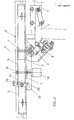
- a longitudinal guide 2 is arranged parallel to the table edge on the left, seen in the feed direction, parallel to the saw blade plane.
- the table end is provided with mounting plates 3, on which the longitudinal guide 2 receiving carrying straps 4 can be detachably fixed by means of a plug and clamp lock.
- On the longitudinal guide 2 is a a slide carriage 5 forming a workpiece holder is slidably mounted. The displacement movement is limited by end stops, which are designed here as the spring bolt 6 passing through the profile tube forming the longitudinal guide 2, which can be retracted against the force of the release spring acting thereon, so that the slide 5 can be removed from the longitudinal guide 2.
- the carriage 5 has a table top 7 forming a workpiece support surface, which is provided with a workpiece stop 8 arranged transversely to the feed direction, ie transversely to the longitudinal direction of the longitudinal guide 2.
- the workpiece stop is pivotable for making miter cuts about an axis a perpendicular to the support surface of the table top 7.
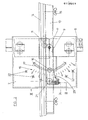
- the workpiece stop 8 is, as can best be seen from FIGS. 2 and 3, in two parts and consists of an index rail 9 pivotably mounted on the table top 7 about the axis a and a stop rail 10 pivotably mounted thereon about an axis coaxial with the axis a
- a spring pin 11 is simply provided which penetrates the index rail 9 and the stop rail 10 without play and engages without play in a table-side bearing bore.
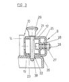
- the index rail 9 is, as can best be seen from FIG. 3, U-shaped in cross section and arranged in such a way that its parallel legs 12 overlap or underneath the stop rail 10, which gives the stop rail 10 excellent freedom from wobble.
- the stop rail 10 consists of a between the legs 12 of the Indexing rail 9 engaging support tube 13 and an extension bar 14 placed thereon, which can be detachably fixed thereto by means of clamping screws 15.
- the pivotability of the workpiece stop 8 about the pivot axis a allows the setting of any desired miter angle.
- the pivotable workpiece stop 8 can be fixed in a rotationally fixed manner relative to the table top 7.
- a clamping screw 16 is provided which engages on the index rail 9 and extends through an arcuate longitudinal groove 17 of the table top 7.
- the clamping screw 16 is assigned a manually operable clamping nut 18 which is arranged in the region of the underside of the table and by means of which a clamp closure can be produced.
- the arcuate groove 17 follows the course of an ice around the axis a with the distance of the clamping screw 16 from the axis a corresponding radius.
- the clamping screw 16 extends through the legs 12 of the index rail 9, so that they are pressed with a corresponding clamping force on the support tube 13 of the stop rail 10 encompassed thereby.
- the stiffness of the support tube 13 ensures that the U-shaped index rail is not deformed under the action of the clamping force.
- the clamping nut 18 is loosened, any desired angular position can be set within the arcuate groove 17.
- the table top 7 is designed as a scale support for a molded-in or glued-on scale 19, to which an adjustment edge 20 of the index rail is assigned, as shown in FIG. 2.
- the setting edge 20 has a sharp edge on the scale side.
- the index rail 9 is simply punched out in the area of its rear side to form the setting edge 20.
- the zero position of the workpiece stop 8 i.e. the position in which the workpiece-side stop edge of the workpiece stop runs exactly at an angle of 90 degrees to the feed direction of the slide 5 or to the plane of the associated saw blade or to the table edge parallel to the saw blade, is in the region of the middle of the Scale 19 or the arcuate groove 17, which enables a two-sided deflection of the workpiece stop, ie a deflection over the zero position both in the positive sense and in the negative sense.
- the workpiece stop can be fixed by means of an index pin 21, which can be detachably received on the index rail 9 and inserted into an assigned index hole 22 of the table top 7.
- the index pin 21 engages through the legs 12 of the index rail 9 and through that of the legs 12 encompassed support tube 13 of the stop rail 10 therethrough.
- a precise fit is provided in the region of the legs 12.
- an index-shaped slot 23 is assigned to the index pin 21, which enables the stop rail 10 to be deflected relative to the index rail 9.
- This possibility of relative movement between index rail 9 and stop rail 10 is necessary in order to be able to carry out a precise adjustment of the stop edge on the workpiece in the zero position.
- Such adjustment is at least at least when re-installing a machine, in order to compensate for inaccuracies resulting from the local conditions of the installation site.
- an adjusting device 24 indicated only by its center line, is provided, by means of which the stop rail 10, which is pivotable relative to the index rail 9 and is mounted thereon, can be adjusted.
- the actuating device 24 here, as shown in FIG. 3, consists of a on the stop rail 10, i.e. ar the support tube 13, and on the index rail 9 engaging clamping screw 25, which is supported on the stop rail side with its head 26 and index rail side with an adjusting nut 27.
- the distance between the head 26 and the adjusting nut 27, which is set by a corresponding rotation of the adjusting nut 27, and thus the angle set between the index rail 9 and the stop rail 10, can be fixed by the clamping nuts 28 assigned to the head 26 or the adjusting nut 27, which lock the indexing rail 9 against the assigned adjusting lever 27 and clamp the support tube 13 of the stop rail 10 against the assigned screw head 26.
- a plurality of index holes 22 are provided on a pitch circle around the pivot axis a, for quickly fixing the workpiece stop in all important angular positions.
- the partial circle of the index holes 22 parallel to the arcuate groove 17 or to the scale 19 leads in both directions beyond the zero position of the workpiece stop.
- the index holes 22 provided can be arranged with the same or different pitches.
- the index holes are 15 degrees apart arranged, whereby the important angles of 30 degrees and 45 degrees are detected. In some cases, an even finer division, for example a 5-degree division, can also be useful. In this case, approximately two index hole partial circles can be provided, on which the index holes can be arranged offset from one another.
- the index rail 9 and the support tube 13 of the stop rail 10 would also have to be provided with two radially staggered receptacles for an index pin 21.
- the angular positions specified by index holes 22 can be determined simply by inserting the index pin 21.
- the clamping screw 16 is therefore only required in the range of the intermediate positions which can be set with the aid of the scale 19 and the setting edge 20.
- the index holes 22 are designed as simple fitting bores to which a cylindrical section of the index pin 21 is assigned. It would also be conceivable to design the index holes 22 as conical holes, to which conical sections of the index pin 21 are assigned. In such a case, it would be ensured that the index pin 21 always comes to rest on the hole-side seat in a full and play-free manner.
- this is provided with a button-like handle 29 arranged in the region of its upper end. In the area of its lower end, an insertion phase 30 can be provided, which facilitates the insertion of the index pin 21 into the associated receptacles on the workpiece stop and on the table top.
Landscapes
- Life Sciences & Earth Sciences (AREA)
- Engineering & Computer Science (AREA)
- Mechanical Engineering (AREA)
- Wood Science & Technology (AREA)
- Forests & Forestry (AREA)
- Sawing (AREA)
- Character Spaces And Line Spaces In Printers (AREA)
- Lubricants (AREA)
- Milling, Drilling, And Turning Of Wood (AREA)
Priority Applications (1)
| Application Number | Priority Date | Filing Date | Title |
|---|---|---|---|
| AT84101782T ATE48786T1 (de) | 1983-03-02 | 1984-02-21 | Gehrungsanschlag. |
Applications Claiming Priority (2)
| Application Number | Priority Date | Filing Date | Title |
|---|---|---|---|
| DE3307287 | 1983-03-02 | ||
| DE3307287A DE3307287C2 (de) | 1983-03-02 | 1983-03-02 | Gehrungsanschlag für Holzbearbeitungsmaschinen |
Publications (3)
| Publication Number | Publication Date |
|---|---|
| EP0118077A2 true EP0118077A2 (fr) | 1984-09-12 |
| EP0118077A3 EP0118077A3 (en) | 1987-10-14 |
| EP0118077B1 EP0118077B1 (fr) | 1989-12-20 |
Family
ID=6192250
Family Applications (1)
| Application Number | Title | Priority Date | Filing Date |
|---|---|---|---|
| EP84101782A Expired EP0118077B1 (fr) | 1983-03-02 | 1984-02-21 | Butée à onglets |
Country Status (3)
| Country | Link |
|---|---|
| EP (1) | EP0118077B1 (fr) |
| AT (1) | ATE48786T1 (fr) |
| DE (2) | DE3307287C2 (fr) |
Cited By (1)
| Publication number | Priority date | Publication date | Assignee | Title |
|---|---|---|---|---|
| WO2004043635A1 (fr) * | 2002-11-14 | 2004-05-27 | Wilhelm Altendorf Gmbh & Co. Kg | Butee a onglet |
Families Citing this family (4)
| Publication number | Priority date | Publication date | Assignee | Title |
|---|---|---|---|---|
| DE3915376A1 (de) * | 1989-05-11 | 1990-11-15 | Herbert Lang | Schablone |
| DE19519646C1 (de) * | 1995-05-30 | 1996-09-12 | Scheppach Maschf J | Querschneideinrichtung für Holzbearbeitungsmaschinen |
| US6530303B1 (en) | 1999-06-10 | 2003-03-11 | Black & Decker Inc. | Table saw |
| CN112589645B (zh) * | 2020-11-27 | 2021-12-10 | 张建洁 | 一种建筑异形钢材专用的固定切割一体机 |
Family Cites Families (5)
| Publication number | Priority date | Publication date | Assignee | Title |
|---|---|---|---|---|
| DE13538C (de) * | J. BRÄUTIGAM in Nürnberg, Weifsgerbergasse 12 | Gehrungssäge | ||
| US1113152A (en) * | 1913-11-01 | 1914-10-06 | American Wood Working Machinery Co | Cut-off gage for sawing-machines. |
| US2010882A (en) * | 1934-10-18 | 1935-08-13 | Walker Turner Company Inc | Self-indexing miter gauge |
| US3872761A (en) * | 1973-12-03 | 1975-03-25 | Stanley Works | Mitre box with improved indexing means |
| DE2524341A1 (de) * | 1975-06-02 | 1976-12-16 | Scharwaechter Kg | Vorrichtung zum winkelgerechten ablaengen langgestreckter flach- oder stabmateriallaengen |
-
1983
- 1983-03-02 DE DE3307287A patent/DE3307287C2/de not_active Expired
-
1984
- 1984-02-21 EP EP84101782A patent/EP0118077B1/fr not_active Expired
- 1984-02-21 DE DE8484101782T patent/DE3480776D1/de not_active Expired - Fee Related
- 1984-02-21 AT AT84101782T patent/ATE48786T1/de not_active IP Right Cessation
Cited By (2)
| Publication number | Priority date | Publication date | Assignee | Title |
|---|---|---|---|---|
| WO2004043635A1 (fr) * | 2002-11-14 | 2004-05-27 | Wilhelm Altendorf Gmbh & Co. Kg | Butee a onglet |
| CN100404180C (zh) * | 2002-11-14 | 2008-07-23 | 威尔海姆-阿尔坦道夫两合公司 | 斜接止挡 |
Also Published As
| Publication number | Publication date |
|---|---|
| EP0118077A3 (en) | 1987-10-14 |
| DE3480776D1 (de) | 1990-01-25 |
| DE3307287A1 (de) | 1984-09-06 |
| ATE48786T1 (de) | 1990-01-15 |
| EP0118077B1 (fr) | 1989-12-20 |
| DE3307287C2 (de) | 1986-01-30 |
Similar Documents
| Publication | Publication Date | Title |
|---|---|---|
| EP0144490A2 (fr) | Dispositif de guidage de foreuse ou fraise pour machines échangeables d'entraînement | |
| DE2339873C2 (de) | Anordnung zum Einstellen und Befestigen eines ein Schneidplättchen tragenden Blocks in einer nutförmigen Aufnahme im Werkzeugkörper eines spanabhebenden Werkzeugs | |
| EP0315728B1 (fr) | Dispositif pour la coupe de carreaux | |
| WO1990002633A2 (fr) | Dispositif de serrage | |
| DE19715424A1 (de) | Vorrichtung für das Einbringen von Dübelbohrungen in zwei rechtwinkelig miteinander zu verbindende Bretter | |
| EP0116260A2 (fr) | Dispositif pour fixer un objet | |
| EP0479818B1 (fr) | Butee parallele et angulaire | |
| EP0118077B1 (fr) | Butée à onglets | |
| EP0598218B1 (fr) | Support d'outil pour supporter et guider longitudinalement des outils, notamment des forets pour la pierre ou des scies | |
| DE4409540A1 (de) | Stationär betriebene Auslegerkreissäge | |
| EP3702100B1 (fr) | Dispositif de butée | |
| DE3422570A1 (de) | Messerhalter fuer ein scherenschnittmesser an rollenschneidmaschinen | |
| DE3026513C2 (de) | Werkzeug zum Aufbohren und Plansenken | |
| DE202022100251U1 (de) | Winkelanschlag | |
| DE4329372A1 (de) | Spanneinrichtung zum Halten von Werkstücken | |
| EP0174640B1 (fr) | Dispositif de rognage pour une scie circulaire à table de menuisier | |
| DE3105181A1 (de) | Schneidwerkzeug | |
| EP0117505B1 (fr) | Machine pour travailler le bois | |
| DE19519645C1 (de) | Querschneideinrichtung | |
| DE3513806A1 (de) | Werkstueckniederhalter mit spannhebel | |
| DE2158191C3 (de) | Vorrichtung zum Entgraten von geraden Blechbändern | |
| DE19527098C1 (de) | Zinkenschneideinrichtung | |
| DE2059558C3 (de) | Verstellbarer Endanschlag | |
| DE2025374A1 (de) | Vorrichtung zum stationären Betrieb von in eine motorisch angetriebene Hand bohrmaschine eingesetzten, umlaufenden Werkzeugen | |
| DE2745402A1 (de) | Werkzeughalterung fuer eine werkzeugmaschine |
Legal Events
| Date | Code | Title | Description |
|---|---|---|---|
| PUAI | Public reference made under article 153(3) epc to a published international application that has entered the european phase |
Free format text: ORIGINAL CODE: 0009012 |
|
| AK | Designated contracting states |
Designated state(s): AT BE CH DE FR GB IT LI SE |
|
| PUAL | Search report despatched |
Free format text: ORIGINAL CODE: 0009013 |
|
| AK | Designated contracting states |
Kind code of ref document: A3 Designated state(s): AT BE CH DE FR GB IT LI SE |
|
| 17P | Request for examination filed |
Effective date: 19880315 |
|
| 17Q | First examination report despatched |
Effective date: 19890323 |
|
| GRAA | (expected) grant |
Free format text: ORIGINAL CODE: 0009210 |
|
| AK | Designated contracting states |
Kind code of ref document: B1 Designated state(s): AT BE CH DE FR GB IT LI SE |
|
| REF | Corresponds to: |
Ref document number: 48786 Country of ref document: AT Date of ref document: 19900115 Kind code of ref document: T |
|
| GBT | Gb: translation of ep patent filed (gb section 77(6)(a)/1977) | ||
| ITF | It: translation for a ep patent filed | ||
| REF | Corresponds to: |
Ref document number: 3480776 Country of ref document: DE Date of ref document: 19900125 |
|
| ET | Fr: translation filed | ||
| PLBE | No opposition filed within time limit |
Free format text: ORIGINAL CODE: 0009261 |
|
| STAA | Information on the status of an ep patent application or granted ep patent |
Free format text: STATUS: NO OPPOSITION FILED WITHIN TIME LIMIT |
|
| 26N | No opposition filed | ||
| ITTA | It: last paid annual fee | ||
| PGFP | Annual fee paid to national office [announced via postgrant information from national office to epo] |
Ref country code: GB Payment date: 19911217 Year of fee payment: 9 |
|
| PGFP | Annual fee paid to national office [announced via postgrant information from national office to epo] |
Ref country code: FR Payment date: 19920115 Year of fee payment: 9 |
|
| PGFP | Annual fee paid to national office [announced via postgrant information from national office to epo] |
Ref country code: CH Payment date: 19920120 Year of fee payment: 9 |
|
| PGFP | Annual fee paid to national office [announced via postgrant information from national office to epo] |
Ref country code: AT Payment date: 19920121 Year of fee payment: 9 |
|
| PGFP | Annual fee paid to national office [announced via postgrant information from national office to epo] |
Ref country code: SE Payment date: 19920122 Year of fee payment: 9 |
|
| PGFP | Annual fee paid to national office [announced via postgrant information from national office to epo] |
Ref country code: BE Payment date: 19920123 Year of fee payment: 9 |
|
| PG25 | Lapsed in a contracting state [announced via postgrant information from national office to epo] |
Ref country code: GB Effective date: 19930221 Ref country code: AT Effective date: 19930221 |
|
| PG25 | Lapsed in a contracting state [announced via postgrant information from national office to epo] |
Ref country code: SE Effective date: 19930222 |
|
| PG25 | Lapsed in a contracting state [announced via postgrant information from national office to epo] |
Ref country code: LI Effective date: 19930228 Ref country code: CH Effective date: 19930228 Ref country code: BE Effective date: 19930228 |
|
| BERE | Be: lapsed |
Owner name: JOSEF SCHEPPACH MASCHINENFABRIK G.M.B.H. & CO. Effective date: 19930228 |
|
| GBPC | Gb: european patent ceased through non-payment of renewal fee |
Effective date: 19930221 |
|
| PG25 | Lapsed in a contracting state [announced via postgrant information from national office to epo] |
Ref country code: FR Effective date: 19931029 |
|
| REG | Reference to a national code |
Ref country code: CH Ref legal event code: PL |
|
| REG | Reference to a national code |
Ref country code: FR Ref legal event code: ST |
|
| EUG | Se: european patent has lapsed |
Ref document number: 84101782.5 Effective date: 19930912 |
|
| PGFP | Annual fee paid to national office [announced via postgrant information from national office to epo] |
Ref country code: DE Payment date: 19961223 Year of fee payment: 14 |
|
| PG25 | Lapsed in a contracting state [announced via postgrant information from national office to epo] |
Ref country code: DE Free format text: LAPSE BECAUSE OF NON-PAYMENT OF DUE FEES Effective date: 19981103 |