EP0118121A2 - Anordnung zur Kodierung und Dekodierung von sequentiellen Nachrichten in Datenverarbeitungssystemen - Google Patents
Anordnung zur Kodierung und Dekodierung von sequentiellen Nachrichten in Datenverarbeitungssystemen Download PDFInfo
- Publication number
- EP0118121A2 EP0118121A2 EP84102240A EP84102240A EP0118121A2 EP 0118121 A2 EP0118121 A2 EP 0118121A2 EP 84102240 A EP84102240 A EP 84102240A EP 84102240 A EP84102240 A EP 84102240A EP 0118121 A2 EP0118121 A2 EP 0118121A2
- Authority
- EP
- European Patent Office
- Prior art keywords
- code
- symbols
- variable length
- augmented
- character
- Prior art date
- Legal status (The legal status is an assumption and is not a legal conclusion. Google has not performed a legal analysis and makes no representation as to the accuracy of the status listed.)
- Granted
Links
- 230000006872 improvement Effects 0.000 title description 8
- 230000003190 augmentative effect Effects 0.000 claims abstract description 230
- 238000000034 method Methods 0.000 claims abstract description 110
- 230000005540 biological transmission Effects 0.000 claims abstract description 37
- 238000003860 storage Methods 0.000 claims abstract description 18
- 238000004891 communication Methods 0.000 claims abstract description 14
- 230000003416 augmentation Effects 0.000 claims description 78
- 238000013500 data storage Methods 0.000 claims description 17
- 230000001360 synchronised effect Effects 0.000 claims description 6
- 230000001174 ascending effect Effects 0.000 claims description 3
- 230000011664 signaling Effects 0.000 claims description 3
- 238000000638 solvent extraction Methods 0.000 claims 3
- 238000009795 derivation Methods 0.000 claims 1
- 238000005192 partition Methods 0.000 claims 1
- 238000012163 sequencing technique Methods 0.000 claims 1
- 238000010276 construction Methods 0.000 abstract description 27
- 230000008569 process Effects 0.000 description 52
- 238000010586 diagram Methods 0.000 description 30
- 230000007704 transition Effects 0.000 description 30
- 238000004422 calculation algorithm Methods 0.000 description 26
- 238000012217 deletion Methods 0.000 description 15
- 230000037430 deletion Effects 0.000 description 15
- 238000012545 processing Methods 0.000 description 12
- 238000001514 detection method Methods 0.000 description 10
- 238000012937 correction Methods 0.000 description 5
- 230000002459 sustained effect Effects 0.000 description 5
- 238000009826 distribution Methods 0.000 description 4
- 230000015654 memory Effects 0.000 description 4
- 230000008901 benefit Effects 0.000 description 3
- 238000006243 chemical reaction Methods 0.000 description 3
- 230000000295 complement effect Effects 0.000 description 3
- 230000001934 delay Effects 0.000 description 3
- 239000011159 matrix material Substances 0.000 description 3
- 238000011084 recovery Methods 0.000 description 3
- 108091028043 Nucleic acid sequence Proteins 0.000 description 2
- 230000006870 function Effects 0.000 description 2
- 230000006698 induction Effects 0.000 description 2
- 238000003780 insertion Methods 0.000 description 2
- 230000037431 insertion Effects 0.000 description 2
- 238000007689 inspection Methods 0.000 description 2
- 230000002093 peripheral effect Effects 0.000 description 2
- 238000010926 purge Methods 0.000 description 2
- 238000000926 separation method Methods 0.000 description 2
- 230000009897 systematic effect Effects 0.000 description 2
- 108020004414 DNA Proteins 0.000 description 1
- XUIMIQQOPSSXEZ-UHFFFAOYSA-N Silicon Chemical compound [Si] XUIMIQQOPSSXEZ-UHFFFAOYSA-N 0.000 description 1
- 238000013459 approach Methods 0.000 description 1
- 230000002457 bidirectional effect Effects 0.000 description 1
- 238000004364 calculation method Methods 0.000 description 1
- 230000008859 change Effects 0.000 description 1
- 238000012512 characterization method Methods 0.000 description 1
- 238000004883 computer application Methods 0.000 description 1
- 230000003111 delayed effect Effects 0.000 description 1
- 230000001419 dependent effect Effects 0.000 description 1
- 238000011161 development Methods 0.000 description 1
- 230000000694 effects Effects 0.000 description 1
- 238000005516 engineering process Methods 0.000 description 1
- 238000011156 evaluation Methods 0.000 description 1
- 239000000463 material Substances 0.000 description 1
- 230000001343 mnemonic effect Effects 0.000 description 1
- 238000012544 monitoring process Methods 0.000 description 1
- 230000003287 optical effect Effects 0.000 description 1
- 238000005457 optimization Methods 0.000 description 1
- 239000013612 plasmid Substances 0.000 description 1
- 238000002360 preparation method Methods 0.000 description 1
- 238000007639 printing Methods 0.000 description 1
- 229910052710 silicon Inorganic materials 0.000 description 1
- 239000010703 silicon Substances 0.000 description 1
- 238000006467 substitution reaction Methods 0.000 description 1
- 238000012546 transfer Methods 0.000 description 1
- 230000009466 transformation Effects 0.000 description 1
- 238000000844 transformation Methods 0.000 description 1
- 238000013519 translation Methods 0.000 description 1
- 230000001960 triggered effect Effects 0.000 description 1
- 241001515965 unidentified phage Species 0.000 description 1
- 239000013598 vector Substances 0.000 description 1
Images


Classifications
-
- G—PHYSICS
- G11—INFORMATION STORAGE
- G11B—INFORMATION STORAGE BASED ON RELATIVE MOVEMENT BETWEEN RECORD CARRIER AND TRANSDUCER
- G11B20/00—Signal processing not specific to the method of recording or reproducing; Circuits therefor
- G11B20/10—Digital recording or reproducing
- G11B20/14—Digital recording or reproducing using self-clocking codes
- G11B20/1403—Digital recording or reproducing using self-clocking codes characterised by the use of two levels
- G11B20/1423—Code representation depending on subsequent bits, e.g. delay modulation, double density code, Miller code
- G11B20/1426—Code representation depending on subsequent bits, e.g. delay modulation, double density code, Miller code conversion to or from block codes or representations thereof
-
- H—ELECTRICITY
- H04—ELECTRIC COMMUNICATION TECHNIQUE
- H04L—TRANSMISSION OF DIGITAL INFORMATION, e.g. TELEGRAPHIC COMMUNICATION
- H04L7/00—Arrangements for synchronising receiver with transmitter
- H04L7/04—Speed or phase control by synchronisation signals
Definitions
- the present invention relates to a method of and/or apparatus for encoding and decoding sequential information in data handling systems and relates particularly to the use of codes having the property of enabling character synchronization to be established substantially automatically upon applying simple decoding procedures.
- the present invention relates to applications of these codes to the encoding and serial transmission or storage of digitally represented data.
- word will refer to any sequential ordering of characters which have been defined such that this ordering has significance in representing information content. It is possible that a word so defined will in the process of an encoding scheme be associated with characters taken from some further system of represention or character set. Thus the terms “character” and “word” or “code” and “code word”, depending on the context, may be interchangeable without introducing any ambiguity.
- a finite code is called synchronizable if and only if there exists a least integer m such that the knowledge of the last m characters of a message suffices to determine separation of code words.
- BSD bounded synchronization delay
- the invention may broadly be said to consist in apparatus in the encoding and decoding of sequential information in data handling systems including, data transfer, data storage and/or data processing systems, said apparatus comprising either one or a combination of more than one of the following integers (A) through (E), or a combination of integers (A) through (E) with integer (F), or a combination of integers (C) and (H) with any, all or none of (A), (B), (D), (E), (F), (G) said integers comprising:-
- the augmentation means to form said augmented codes in accordance with (A) comprises a means to form a first set of unique character symbols, a means to repeat said first set of characters, a means to delete a selected character and to augment said repeated first set of characters by prefixing said repeated first set of characters with said deleted character to form an unambiguous code set, and a means to assign values to elements of said code set.
- said augmentation means further include means to repeat said steps a selected number of times, said first set of unambiguous characters of one cycle of steps, other than in the first cycle, comprising the unambiguous code set of the preceding cycle of steps.
- augmented character set resulting from repeated application of a single cycle of said augmentation process will hereinafter be referred to as an augmented set of degree n, where n is an integer equal to the number of times said augmentation process is repeated for said augmented character set.
- said means of forming a corresponding set of fixed length binary codes or depletion codes includes means for performing the steps of forming the complete list of 2 1+n fixed length binary numerical codes of length (1+n) bits, where 1 is the number of times said augmentation step has been repeated for the augmented codes corresponding to the desired depletion codes, n is the smallest integer satisfying the relationship where s is the integer number of characters in said first set, means to delete all binary codes for which the n least significant bits corresponding numerically to an integer w satisfy some criterion, means to group remaining fixed length codes, means to delete binary codes from alternate groups, further means to regroup the remaining codes and to further delete selected characters from alternate groups, and means to repeat these steps until a desired set of block codes is reached.
- said means to first delete said binary codes in which the n least significant bits correspond to an integer w deletes only said binary codes for which said w satisfies the criterion that and said means leaves no other codes in said remaining codes which satisfy this criterion.
- said means to group said remaining binary codes forms groups comprising exactly s codes each, and preferably said means to regroup said binary codes subsequent to said deletions in alternate groups forms said binary codes in groups double in size of previous grouping or regrouping cycle and includes in code count for each group an allotted space corresponding to previous deletions.
- said means to delete said binary codes in alternate groups includes a deletion in the first group in each cycle, said cycle involving the steps of both grouping or regrouping and deleting, and deletions in the subsequent alternate groups corresponding in relative position within the respective groups to the said deletion in said first group.
- said means to delete said binary codes is limited to deleting just one code in each alternate group during each cycle, said cycle comprising the steps of grouping or regrouping and deleting.
- said means to repeat said cycle of grouping or regrouping and deleting is limited to a total of q cycles.
- said encoding means repeats said augmenting step a selected number of times, said first set of unambiguous characters of one cycle of steps, other than the first cycle comprising the unambiguous code set of the preceding cycle of steps.
- said means used for checking codes in said sequence includes means for checking if received code, as decoded using said augmentation set of a degree n for n ⁇ q, is other than the (n+1) prefix character as used in the next subsequent augmentation cycle i.e. the (n+l)th augmentation generating said augmented set of degree (n+1), if said checked code is in fact not said (n+l)th prefix then means to decode commences to use said augmented set of degree (n+1), if said checked code is identical to said (n+1)th prefix then said means to decode continues to use said augmented set of degree n.
- said value q at which synchronization is deemed to have occurred is the same as the degree of augmented code set used to encode a data sequence to form said augmented code sequence.
- the invention may broadly be said to consist in a method of encoding and decoding of sequential information in data handling systems, said method comprising any one or more of the following steps (a) through (e), or combinations of any one or more of steps (a) through (e) with steps (f), or combinations or step (c) and step (g) with any one or more steps (a), (b), (d), (e), (f) or with none of the steps (a), (b), (c), (d), (e), (f), said steps comprising:
- the method of forming said augmented codes in accordance with (a) includes the steps of forming a code set by forming a first set of unique character symbols, repeating said first set of characters, deleting a selected character and augmenting said repeated first set of characters by prefixing said repeated first set of characters with said deleted character to form an unambiguous code set and assigning values to elements of said code set.
- the said method further includes the steps of repeating said steps a selected number of times, said first set of unambiguous characters of one cycle of steps, other than the first cycle, comprising the unambiguous code set of the preceding cycle of steps, said augmented character set resulting from repeated application of a single cycle of said augmentation process is as before referred to as an augmented set of degree n, where n is an integer equal to the number of times said augmentation process is repeated for said augmented character set.
- said criterion used in accordance with the preceding paragraph comprises a means for checking if received code as decoded using augmented set of a degree n, for some integer n, is other than the (n + l)th prefix character used in the next subsequent augmentation cycle, i.e. the (n + 1)th augmentation, and proceeding to next subsequent augmentation set of degree (n + I) if said code is in fact not a prefix. If said received code is identical to said (n + 1)th prefix then the decoding continues using said augmented set of degree n.
- said value q at which synchronization is deemed to have occurred in accordance with the preceding paragraph is the same as the degree of the augmented code set used in accordance with step (e) to encode a data sequence.
- said method further includes the steps of forming a corresponding set of fixed length binary codes or depletion codes comprises the steps of forming the complete list of 2 1 + n fixed length binary numerical codes of length (1 + n) bits, where 1 is the number of times said augmentation step has been repeated for the augmented codes corresponding to, the desired depletion codes, n is the smallest integer satisfying the relationship where s is the integer number of characters in said first set, deleting all binary codes for which the n least significant bits corresponding numerically to an integer w satisfy some criterion, grouping of remaining fixed length codes, deleting binary codes from alternate groups, regrouping the remaining codes and deleting selected characters again from alternate groups, and repeating these steps until a desired set of block codes is reached.
- said binary codes first deleted in accordance therewith before said grouping is performed, and inwhich the n least significant bits correspond to an integer w all satisfy the criterion that and further, no other codes remaining in the list satisfy this ) criterion.
- the number of codes in a group for each cycle of steps, involving both grouping and deleting starts with s codes for each group and is doubled each repeated cycle.
- a deletion is made in the first group in each cycle involving the steps of both grouping and deleting, and deletions in the subsequent alternate groups correspond in their relative position, within the respective groups, to the code deleted in the first group.
- steps of regrouping and deleting are carried out q times.
- any one of said methods which includes forming said augmented codes as set forth in step (a) includes repeating said augmenting step a selected number of times, said first set of unambiguous characters of one cycle of steps, other than the first cycle comprising the unambiguous code set of the preceding cycle of steps.
- the invention may broadly be said to consist in the parts, elements and features referred to or indicated in the specification of this application, individually or collectively and any and all combinations of any two or more of said parts, elements or features, and where specific integers are mentioned herein which have known equivalents are deemed to be incorporated herein as if individually set forth.
- a second character set C m+1 ⁇ D m+1 i ⁇ comprising the (2n - 1) character elements, D m+1 i ; is defined to be the augmented character set of C m if it satisfies the following construction.
- a procedure to produce an augmented set can begin by writing a word list consisting of the original character set C m , twice over.
- one of the initial characters D m i (any one) in the first part of the list is deleted and the deleted character is prefixed to each of the characters in the second half of the list. Note that such a construction specifically includes the combination formed by appending the prefix to itself.
- Each word in the list is then assigned uniquely to one of the character symbols D m+1 i of the set C m+1 .
- the characters resulting from a single application of the augmentation rule can be of no more than one or two of the characters D . from the set C m .
- FIG. 6a An example of apparatus for performing the above augmentation algorithm is depicted in block diagram form in Figure 6a.
- a character set C herein will be called complete if it contains all symbols necessary to represent a desired class of character strings, S ⁇ C ⁇ .
- the alphabet for example is not a complete set since further punctuation and delimiting characters are required to support correct syntax in the English language, whereas the ASCII codes used in conjunction with computer terminal communications systems do form a complete character set.
- a character sequence S ⁇ C ⁇ , defined on the character set C, will herein be called positively unbounded if for every character in S ⁇ C ⁇ there exists a subsequent character. (see section XXII)
- FIG. 6b An example of apparatus for performing multiple augmentation is depicted in block diagram form in Figure 6b.
- a significant property possessed by the augmented codes of the invention is their ability to recover character synchronization automatically during the decoding process following any perturbation or break during serial comma-free transmission of an encoded sequence. This property is stated for the general case in theorem 3 (hereinafter).
- An example of the synchronization process is illustrated in table 2 (hereinafter) .
- Augmented binary code sets are of particular interest in this basically binary world of digital computers and communications systems using a binary number base.
- Table 1 shows this and also the further repeated application of the augmentation process producing an augmented binary character encoding scheme of the 4th degree, which is subsequently used to illustrate a number of the properties of the augmented codes.
- the received string is shown to omit the fifth data bit corresponding to a simulated error.
- the recovered character string is shown to have resynchronized in this case after only tow incorrect characters.
- Other simulated errors may be tried such as scrambling, bit loss etc., and in each case the comma-free codes displayed will resynchronize.
- a number of useful results may be derived for this family of augmented binary codes.
- either the '1' or the '0' may be used as the initial prefixing character.
- two sets each of three characters and each of the first degree exist, and may be designated C l .
- the first is simply the reciprocal representation of the second and, stemming directly from this symmetry in the initial augmentation, it will be apparent that at any higher level of augmentation there will always be two systems of codes which are found to be identical if one interchanges the 1's and 0's for one of these systems.
- the complete class of augmented binary codes at any degree of augmentation comprises two systems of anti-symmetric codes.
- the total number of sets within any family may be calculated using the result presented previously for expressing the size of an augmented code set. For the augmented binary codes of degree m this reduced to; The number of sets in the family F is then given by; IX. Minimal Code Sets
- the average character size for the new set will grow minimally with each augmentation.
- the variation in character lengths will also be minimal although the smallest character representations will not in general be the smallest possible codes for any given degree of augmentation.
- all of the minimal sets at any level of augmentation have identical synchronization properties and serial coding efficiencies as well as identical code-length distributions. In the practical realization of systems using the augmented binary codes it is the minimal sets which will be of most interest and utility and it is these sets which will be generally considered in the examples hereinafter.
- the prefixing characters for the sets may be derived by simply following through the construction of the codes, in each case noting these as they are selected during the augmentation process.
- the first two possible prefixing characters are '0' and '1', each of length 1.
- the next prefixing characters are of length 2 and the four possible codes are '00', '01', '10', '11' of which only three will be available for prefixes for subsequent augmentation processes depending on the previous choice/s of prefix. And so on. This is further illustrated in table 1.
- augmented binary codes may be represented in a block code form which is amenable to internal manipulation within a digital processor and which may be easily transformed into the variable length representation suitable for subsequent serial transmission or storage. (Note that the example given next may be extended in kind, for augmented code sets resulting from a construction using a base character set other than the binary characters.)
- the codes in the list S are grouped into pairs. This is shown in the first column of table 3. A deletion is effected in each of the alternate groups at corresponding positions within each pair of codes and further constrained in that a deletion must occur within the first group.
- column 2 the two possible choices for this step are shown with deletion marked with a 'D' and the corresponding codes which are to be saved are marked with an 'S'.
- the codes are again regrouped, but now into groups of 8 or 2 3 .
- S[1,3] is considered.
- S[1,3,0] has been produced by deleting the first possible such character, '0000'.
- the following comprises an example of the process of generating the augmented codes from the depletion codes. Implicit in the relationship between the two code types is the inverse process of deriving the depletion codes from augmented codes. Examples of apparatus for performing these transformations are depicted in block form in Figures 8, 9a and 9b. Examples of expected kinds of application are depicted in Figures 1 and 2 with example detail of the kinds of variations possible in the implementation of the encoding and decoding operations depicted in figures 3a, 3b, 4a, 4b, 5a and 5b.
- LSB least significant bit
- Each subsequent leading LSB in the block code will determine either the inclusion or omission of respective prefix characters in their respective order of selection. These can essentially only be determined in the order of selection.
- the character deleted to produce set 2 was the code '0001'.
- the literal binary character '1' is then saved as the first of the prefix characters.
- the leading LSB i.e. the bit adjacent to the LSB is now used to denote the presence or absence of the previously determined prefix; in this case the '1'.
- step 2 the code deleted in the first group to produce the set S[1,3] was the code '0011'. Since the leading LSB, and the LSB are each set to '1' this code is interpreted to represent a new prefix created by appending in the order dictated by the block code, the last previous prefix (a '1') appended to the literal binary character (also in this case a '1').
- the new prefix is:
- This new prefix is now associated with the next leading LSB, i.e. the third bit counting from and including the LSB herein referred to as the second leading LSB.
- the second leading LSB then is used to represent the presence or absence of this prefixing code, '11', in the construction of subsequent codes.
- Step 3 shows the construction of set S[1,3,0] with the deletion of the character '0000'. Since none of the leading LSB's are set, no prefix characters are required to derive the third prefix which simply becomes the literal bit or LSB, '0'. This third prefix is noted and, as above, is associated with the next available leading LSB which is clearly the last remaining bit, in other words the MSB.
- any of the residual codes shown in S[1,3,0] may be interpreted to produce the equivalent variable length augmented code.
- these are converted by interpreting the individual bits of a binary depletion code as implying either the inclusion or omission of corresponding prefixes and with the LSB interpreted literally as the LSB of the resulting variable length code.
- Block code '1010' corresponds to the augmented code '010'
- Table 4 illustrates the process of constructing the variable length augmented code from a fixed length depleted code.
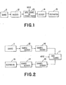
- Figure 1 depicts a block diagram for a general communications system of the kind considered here.
- FIG. 2 An example of a system, such as is depicted in figure 2 is the acoustically-coupled 300 baud terminal/modem-modem/computer link via a transmission means such as a telephone network.
- a means such as a frequency shift keying (FSK) is used in the bidirectional channel encoder and decoder as a method for encoding asynchronous serial binary data.
- the binary data at the terminal/modem or modem/computer interface is most usually a 7-bit ASCII data word marked using a single (low) start bit and followed by two (high) stop bits.
- a sequence of characters thus encoded uses 10 bits/character and may be sent asynchronously since the process for decoding in a decoding means is cued by detection of the low start bit. For the most part character synchronization is established simply, because of the low data exchange rates. Large periods of time are spent with the data channel idle so that the presence of a character is marked unambiguously by the low start bit.
- Loss of synchronization is invariably caused by false start-bit detection due to some channel disturbance or noise. With characters each encoded as fixed length words it is often simply a matter of chance as to whether the receiving device will recover character synchronization during a sustained transmission. The performance of the above system is improved considerably with the application of a suitable set of augmented binary codes as described by way of the example next.
- the augmented binary codes have the right kind of properties for an application such as the one above.
- Each of the 129 codes in the 7th degree set may be assigned to the standard 128 ASCII codes with a single character conveniently left available for transmission during the times the channel is idle. Thus at all times some augmented character will be transmitted even if no actual information is exchanged.
- Table 5 shows one such assignment of the ASCII codes.
- the first column shows the printing character or control character mnemonic followed by the octal and hexadecimal representations of the ASCII binary code in column 2.
- the 4th and 5th and 6th columns list in octal, hex & binary, the block codes respectively corresponding to the variable-length augmented codes of column 7.
- the respective prefix characters for this particular construction are, in the order corresponding to the block code references:
- Table 5 lists an assignment of the 128 ASCII (American Standard Codes for Information Interchange) character codes to seventh degree set of depleted codes and augmented binary codes.
- the '(fil)' character has been assigned one of the shortest character lengths and one in particular which will avoid a sustained error-echo condition. Since E and T are rarely found repeated as capitals they have been assigned to the augmented codes '0000' and '1111' respectively and this avoids a situation where the error-echo condition could be sustained.
- the average length is 6.95 bits/character which compares favorably with the raw 7-bit ASCII code.
- the 6.95 bits/character represents a 44% improvement in the character transmission rate if comparing with the 10 bits/character ordinarily used.
- the improvement may be compared to an increase in the bit transmission rate of from 300 baud to something greater than 430 baud. Yet all we have done is change the encoding scheme.
- each character length with the expected frequency of occurrence for example the letter e occurs about 13% of the time
- the average character size for text is found to approach 5.45 bits/character or equivalently an increase in efficiency of 83% over the 10 bits/character rate. This is equivalent to increasing the bit rate, assuming the existing technology in the 300 baud MODEM, to about 550 baud. It will be clear to any one who has worked with a 300 baud MODEM link that this is a significant improvement.
- Bi- ⁇ -L Binary-Phase-Level binary encoding representation
- the clock information is provided as a transition occurring at the centre of each bit time and the direction of the transition determines the value of the data bit.
- a Bi- ⁇ -L data stream is obtained simply by combining the in-phase data-clock with the NRZ data using a exclusive-or function.
- the combination of the Bi-0-L encoding scheme and the augmented binary codes is significant by comparison with the FSK application in that an error condition is more easily distinguished by the loss of the clock information.
- the encoding system does not contain enough information for the decoder itself to realize it may be decoding noise.
- this Bi- ⁇ -L encoding scheme it is possible to determine with absolute certainty the first character guaranteed to be correct following a break in the transmission, where the break may be detected from the loss of the data clock. Of course, characters decoded following the break and before the first guaranteed character may well be , correct but cannot with certainty be assumed to be valid.
- the synchronous transmission of sixteen distinct character states may be achieved through amplitude and phase modulation of a carrier tone at a line signalling speed of 2400 symbols per second.
- Each of the 16 phase/amplitude modulated states corresponds in turn to the 4-bit codes '0000', '0001', ....'1111'.
- the transmission of an eight bit binary code representing an ASCII character for example is achieved using a pair of the phase/amplitude modulated states although it will be clear that some concern must be given to ensuring correct synchronization of the data during a sustained transmission in order that the message be transposed unambiguously upon receipt.
- the data will be packaged in such a manner as to ensure correct synchronization although this does imply some loss in efficiency in the message transmission rates.
- the above modulation system operates synchronously with the data clocked by a phase modulation in the carrier tone occurring at unit time intervals.
- the x-axis is taken to be the relative phase of the carrier tone during the last previous 4-bit character and in the following symbol period the phase of the character is shifted to one of the 12 radial phase vectors shown at 30 degree intervals and offset from the x-axis by a further 15 degrees.
- These phase states offer a possible twelve data states with four of the twelve further augmented by two levels of amplitude modulation of the carrier to produce a more suitable number of sixteen amplitude/phase states.
- Figure 11b shows five of the twelve phase states with two levels of amplitude modulation producing a complement of seventeen states labelled A through Q and shown with the augmented binary codes of the fourth degree of table 6.
- Table 6 also includes the 5-bit block-code or depletion code representations for reference.
- Augmented Binary Codes Of The Fourth Degree Table 6 lists an intermediate augmented binary set.
- the prefix characters to be used in consecutive augmentations to obtain the codes in table 5 are A, B and C respectively of table 6.
- the block codes of table 5 contain, as the low order bits, the corresponding block codes listed in table 6. Since the characters, A, B and C in table 6 have special significance in this example as prefix characters they have been assigned complementary positions on the phase-plane (figure llb) maximizing the margin of phase discrimination and in turn minimizing the possibility of sustaining an error condition resulting for example from the mistaken substitution of one prefix for another.
- the remaining characters in the 17 character set have been assigned arbitrarily, although it should be noted that the (fil)' character, '0001', of table 5 which corresponds to 'E' of table 6, represents an advance in the carrier phase of 15 degrees every unit time period.
- an optimal assignment of alphabetic and other characters as in table 5 does not necessarily produce a correspondingly optimal assignment at the related intermediate character level.
- this may be observed in the block codes of table 5 where the three MSB's signify the omission or inclusion of the respective prefix characters A, B or C of table 6.
- the presence of a '1' in at least one of these three positions implies that a pair of intermediate characters will be required for the transmission. If two of the positions are set to '1' then three intermediate characters will be required for the transmission, and, finally, if all three MSB's are set to '1', four intermediate characters will be required.
- An algorithm can be developed for determining with certainty character-correct synchronization i.e. the point following which all decoded characters are guaranteed correct.
- the algorithm provides a basis for evaluating the expected synchronization delays in which a probability transition matrix P is used to describe the likelihood of level transitions as shown in table 8.
- the procedure for developing the synchronization algorithm begins with the purging of all of the non-essential codes which may be identified as being those following each first group-boundary in each of the respective lists.
- the result of the purge in the sets S, S[l], S[1,3] and S[1,3,0] of table 3 is shown below in table 7.
- Non-essential Codes Table 7 illustrates the clearing of the non-essential codes in preparation for establishing a transition diagram for determining character-correct synchronization.
- the 'D' markings have been preserved during this step as they are important in determining available transitions between the code lists in the process of determining synchronization.
- the respective lists have been labelled for convenience as level 0 through to level 3 and correspond to the augmented codes of the corresponding degree.
- Allowable transition paths are indicated by the insertion of arrows connecting corresponding codes in adjacent lists, and terminating the path at any code flagged by a 'D'. Determining character-correct synchronization involves starting in level 0 and then, when an appropriate code is received, moving to the highest possible level indicated by the corresponding transition. At the point when level 3 is reached character correct synchronization has been established.
- Table 8 illustrates the determining of the valid transitions.
- a level transition where each level: corresponds to a set whose degree of augmentation is given by the level number (as in table 8), may occur such that the level is always increased by a transition.
- Each transition is initiated by the receipt of a code listed in the current level for which a transition path is shown corresponding to that particular code. Once a transition is initiated the indicated path is followed until the right-most position is reached whether terminated by a 'D' or simply because one has reached level 3.
- Table 9 shows the equivalent information of table 8 but with the block codes replaced with the corresponding variable length codes produced using the prefix codes 1,11,0 for the set S[1,3,0].
- Augmented Code Synchronization Search Table 9 lists the augmented code sets in example of a completed transition diagram.
- any data handling system using augmented codes in the decoding apparatus may include optionally further apparatus for performing character synchronization monitoring and decoding control, as described above and this is further illustrated in figures 5a and 5b.
- An example of a closed code ring such as is shown in table 14, may be formed by connecting the two ends of a finite code string W ⁇ C 0 ⁇ , such as the following which has been coded using an augmented binary code of the seventh degree.
- Forming A Closed Code Ring Table 12 show the construction of a binary closed code ring.
- In.table 12 the ring is shown decoded using table 5. If the ring is decoded in the clockwise direction starting at the point of connection of the two ends of the above finite string W cYOH then the character string "This is a binary ring.” results.
- Table 13 illustrates decoding the ring using codes of table 5.
- Decoding From Some Arbitrary Starting Point Table 14 illustrates synchronization of the decoding process in the case of starting at some arbitrary point on the ring.
- the power of the augmented codes and the related block codes should be clear. If a message or information string comprising a sequential listing of symbolic characters be they electronic represented or whatever, is encoded using a coding scheme such as described herein, then the message may be transmitted and stored for subsequent recovery with the ability for character synchronization to be established and maintained even in the presence of occasional channel disruptions.
- Examples included here show the codes to be particularly suitable for serial transmission or storage of serial data.
- a depletion algorithm provides a convenient method of constructing and manipulating the sets of augmented codes in machines using fixed word sizes.
- the coding system of the present invention would be used in applications such as general digital encoding, remote computer and computer terminal and peripheral interface, data/text transmission and storage, disk memory systems, magnetic tape systems, laser disk systems and so on. Further applications to cyclical systems have been suggested earlier and include, shaft encoders, tachometers, DNA cataloguing and string searching, and so on.
- a further very significant area for application of the augmented codes is in conjunction with the digitizing of analog information and subsequent encoding for transmission or storage. This will have an impact on voice transmission systems, music recording systems, video systems and so on.
- Still another important application includes using the codes for the construction of variable length instructions for micro-computers, computers and/or other processors such that the accidental issinterpretation of bus data is partially compensated for by the assurance that the processor will after several instructions resume the execution of correct program • material. This will be especially important where digital processors are used in electrically noisy environments and where data integrity is of particular significance.
- the codes will be useful especially in applications involving string or pattern searches within sequential information or data.
- the string handling apparatus may utilize the synchronization capabilities of the codes to pack the sequential decoded data using the depletion code representations into fixed word size storage elements.
- the data processing system may then perform standard algorithms for pattern searching on the depletion code sequences with improved storage and processing efficiencies.
- a character set C will herein be called complete if it contains all symbols necessary to represent a desired class of character strings, S ⁇ C ⁇ .
- the alphabet for example, is not a complete set since further punctuation and delimiting characters are required to support correct syntax in the English language, whereas the ASCII codes used in conjunction with computer terminal communications systems do form a complete character set.
- a character sequence, S ⁇ C ⁇ , defined on the character set C, will herein be called positively unbounded if for every character in S ⁇ C ⁇ there exists a subsequent character.
- D 0 D 1 D 2 ... D n for n- infinity forms a positively unbounded sequence.
- C 0 is sufficient to represent all of the desired character strings, S ⁇ C 0 ⁇ , and since we have proved by construction that there exists for each of these a corresponding representation using C 1 , then C 1 must also be complete.
- S ⁇ C 1 ⁇ is the decoded character string corresponding to S ⁇ C 0 ⁇
- S ⁇ C 0 ⁇ is the encoded character string corresponding to S ⁇ C 1 ⁇ .
- the character boundary D 1 /D 1+1 terminates the decoded character D m of the augmented set C n+1 .
- This will be true for both S a and S b since the sequence starting D 1 D 1+1 .., is common to both. But by the uniqueness theorem this decoded sequence must then be common to both S a ⁇ C n+1 ⁇ and S ⁇ C n+1 ⁇ .
- S" ⁇ C n+1 ⁇ D m D m+1 .... satisfying equations (6).
- D 1+k+1 marks the end of a decoded character D m-1 .
- D m-1 D 1+k-1
- D 1+k' D m-2Y D l+k-3
- D l+k-2' D m-3 ... and so on until we reach the character D l .
- the boundary assignments at the interface between W a ⁇ C n ⁇ and S' ⁇ C n ⁇ and the corresponding decoded characters in S a ⁇ C n+1 ⁇ may not be clear.
- Figures 1-10 represent simplified block diagrams of means and methods for encoding and decoding sequential information in data handling systems.
- the block diagrams may represent hardware implementations, firm wired software implementations, or purely software implementations, in a multi-purpose digital processor. They are intended to be representative characterizations of means for implementing the generic methods set forth in the specification and claims.
- Figure 1 illustrates a block diagram of a communications or storage system utilizing a source, which may be the output of a CPU, or a keyboard wherein the output of the source 11 is passed to an encoder 12 for converting the source code into a variable length augmented code.
- the box delineated 13 in Figure 1 represents either a data channel or a storage system.
- the variable length augmented code is particularly suited for data transmission over data channels.
- the fixed length block code or depleted code is particularly suited for the storage system.
- the decoder 14 is the converse of the encoder 12 and restores the variable length code to source code or fixed length block code depending upon the destination 15. Destination 15 may be another CPU, a disk storage means, or a CRT utilizing ASCII codes.
- Figure 2 represents a more conventional data communication system having a source 11 and a source encoder 12 which converts the source code eminating from 11 into the variable length augmented code.
- Channel encoder 16 represents a modum or other means of converting binary digital pulses into analog signals for transmission over a conventional data link 17 such as a telephone line or a microwave link.
- the channel decoder 18 is also a modum which translates the variations in frequency (from frequency shift keying) or variations in phase and amplitude (from a quadrature amplitude modulation) into 1, 2, or 4 bit groups of binary data for the source decoder 14.
- Source decoder 14 then converts the variable length augmented code to either a source code or a fixed length depleted block code for destination 15.
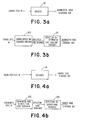
- Figures 3a, 3b expand upon the encoder 12 illustrated in Figures 1 and 2.
- the encoder 12 can be a simple lookup table or data array which is addressable via the given characters of the given source code. Upon receiving the address, the table or array provides the corresponding augmented code sequence out.
- Encoder 12 may also be a hardware implementation, a firm ware implementation, or a software implementation of the algorithm for generating the variable length code from a given source code.
- Figure 3b illustrates a source code to augmented code sequence encoder that utilizes the intermediate depletion code representation which may be useful in data handling or storage.
- the incoming source code is converted to the depleted block codes by the source-depletion sequence encoder 20 to generate a depletion code sequence.
- the depletion to augmented code sequence encoder 21 may be either a lookup table or a hardware, firm ware, or software implementation of the algorithm for generating the augmented variable code from the depletion code as hereinbefore previously described.
- Figure 4a illustrates the decoder 14 of Figures 1 and 2 which receives the augmented code and provides a source code sequence.
- the decoder 14 is a lookup table or data array that is addressable by the variable length augmented code to provide a source code sequence out.
- the decoder may include a synchronizing means for reestablishing synchronization.
- Figure 4b represents an augmented-code to source-code decoder using an intermediate depletion-code representation wherein the augmented code is converted to depletion code by either a lookup table or hardware, firm ware, or software implementing an algorithm for converting the augmented code to a given depletion code.
- the depletion code is then furnished to the depletion to source code decoder 24 which is conventionally a lookup table or data array.
- Figure 5 illustrates an augmented code to source code decoder with code synchronization.
- an optional error, detection and correction system for reestablishing synchronization after error detection is also disclosed.
- the optional error detection and correction system operates independently of the self synchronizing nature of the augmented codes.
- Many computer manufacturers provide specific characters, phase encoding, or parity detection systems to indicate transmission errors.
- the present invention operates independently of these optional error coding detection and correction systems.
- Figure 5a illustrates the manner in which the error detection system is incorporated into the decoding system.
- the decoder 14 receives an augmented code sequence in and provides a source code sequence out. Attached to decoder 14 is a code synchronization monitor and decoder controller 25. There are actually two devices indicated at 25.
- the first device is a code synchronization means which provides initial synchronization or resynchronization in the event of an error or break in communication.
- the code synchronization monitor lists each of the non-prefix characters used in generating the augmented code in a sequential lookup table with separate levels for each level of augmented code C ...to c q used in creating the augmented code.
- the monitor then examines each bit received in the order of occurance until a non-prefix bit from the first level of augmentation is received.
- the monitor advances through the lookup table to the highest level at which the non-prefixing character is found in the lookup table.
- the match search is then expanded from a single bit to the number of bits present in the highest level where the non-prefixing character is found.
- decoder controller Upon establishing the match at the C q level, the decoder controller reestablishes synchronization of decoder 14. It should be noted that decoder l4.may request assistance from the code synchronization monitor, or the code synchronization monitor may be triggered by the optional error detection and correction system 24.
- Figure 5b is an illustration of an augmented code to source code decoder with an intermediate depletion code representation.
- the intermediate depletion to source code decoder provides the ability to use the source code for data storage in the event it is desired to capture an incoming file, or for subsequent CPU processing in the event the central processor is using the depletion code characters rather than other conventional codes such as the ASCII code or EBCDIC code.
- the depleted block codes may be used as general purpose characters in the computer rather than the ASCII or EBCDIC characters. In some environments, it may be desirable to send the depleted block codes along a parallel bus path such as indicated at 26 when the computer is used in a particularly noisy environment.
- the depletion to source code decoder 23 provides a conversion between the depletion code and the source code when it is necessary to convert to a more conventional source code device such as ASCII for a peripheral such as a printer or a CRT display.
- a more conventional source code device such as ASCII for a peripheral such as a printer or a CRT display.
- the operation of the code synchronization monitor and decoder controller 25 is as previously described with respect to Figure 5a.
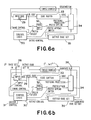
- Figure 6a and 6b disclose block diagrams for forming single and multiple levels of augmentation on a source code character set.
- the devices disclosed in Figures 6a and 6b are identical except for the multiple level of augmentations performed.
- the device illustrated in Figure 6b will generate the augmented codes to be loaded in the ROM lookup table of Figure 10.
- the base character set n indicated at 28 may be binary, or may be any additional initial character set C that is desired to be augmented.
- the additional base character set is supplied to the input code means 29, and control logic 30 selects through the system control 31, the prefix that is to be deleted from the initial code set and added to the replicated code set.
- the code symbol to become a prefix is directed by the control logic 30 to the prefix buffer 32, and the remaining members of the input code set are written into the code buffer 33.
- the first character set C 0 , minus the deleted character set is then transmitted out of the code buffer and through the prefixing processor 34 to the output code set 35.
- the remaining portion of the augmented first level C 0 is then formed by control logic 30 which writes the input code set in 29 back into code buffer 33.
- the prefixing processor 34 As the original set C passes through the prefixing processor 34 the second time, it affixes the prefix present in prefix buffer 32 to each character read into the output code set 35.
- the output code set present in 35 represents the first level augmentation C 1 .
- C is then routed by control logic 30 back to the input code set via bus 36. The process is then repeated with code set C to provide a second level of augmentation.
- the levels of augmentation are determined by the control logic and system control 31. Thus, the operator may select both the deleted codes and the level of augmentation to be performed to create the variable length augmented code set.
- prefix buffer 32 may also be stored for each level of augmentation, and these prefixes may be utilized to create the masker prefix codes used in the depletion code sequence.
- the input code set 29 provides a means for receiving the original character set C 0 and subsequent character sets C 1 ... to C q-1 to be augmented.
- the control logic 30, code buffer 33, prefix buffer 32, prefixing processor 34, and the output code set 35 provide a means for writing the character sets C to C q-1 twice over to form a first half and a second half which duplicates the first half.
- a means is provided for deleting a character in the first half through either control logic 30 or system control 31.
- a prefixing processor 34 prefixes the deleted character to each character symbol in the second half as it passes from code buffer 33 to output code set 35.
- the control logic means 30 sequences the input code means, the buffer means and the prefixing processor q times to form a variable length augmented code of: wherein n represents a number of symbols in the original character set and C q represents the number of variable length augmented code symbols formed in the output code set 35 at the completion of q augmentations.
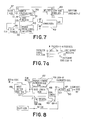
- Figure 7 is an illustration of one means of generating fixed length depletion codes or block codes that may be used in data processing systems or for data storage.
- the clock generator generates three signals, C 1 , e 2 , and C 3 , the interrelationship of which is illustrated in Figure 7a.
- Signal C 3 is used to count out the number of symbols m+1 to be used in the final depletion code wherein 2 (m+1) is equal to or greater than the desired number of characters to be used in data storage and manipulation.
- Clock generator 37 also generates a series of pulses for scan counter 38 for each pulse sent to the depletion code counter 39.
- a number of masked prefix codes are listed in the ROM device 40.
- Scan counter 38 is used to index the prefix codes listed in ROM 40 and provide a first signal representative of the length of the prefix code to the code masker 41.
- comparator 42 The appropriate number of pulses, and the position of those pulses as determined by code masker 41 is then furnished to comparator 42 along the signal line indicated at input a. Simultaneously, the prefix code is transmitted to comparator 42 along input line b. The comparator then compares the signal on input a and input b, and when the signals are not equal, it enables the depletion code output register 43 to load a valid depletion code from the depletion code counter 39. The entire process is repeated with each load pulse from clock generator 37 along signal line c 2 .
- FIG 8 illustrates a block diagram of depletion to augmented code sequence encoder as previously described in Figure 3b.
- the depletion code is first stored in input buffer 46 which then simultaneously indexes two ROM lookup tables, 47 and 48.
- ROM 47 contains a variable length augmented code symbol that corresponds to each of the depleted codes.
- ROM 48 contains the length in digits of the variable length codes stored at the same address in ROM 47.
- the output of ROM 48 relating to the code length is then fed to counter 49 which sends a control pulse and a code length signal to shift register 50 to prepare the register for receiving the new augmented code from ROM table 47.
- a load signal is returned to the input buffer in code register 46 to load a new depletion code for translation.
- Figure 9a is a block diagram illustrating one means that will translate the augmented code into depletion code by means of a ROM lookup table.
- the augmented code being of variable length is first loaded in the input code buffer 51. Inasmuch as the length of the augmented code will vary, the elapsed time used to translate the code will vary, and some means is needed to restart the loading sequence with each new word. In addition, it is impossible for the input code buffer 51 to know when a complete word has been assembled inasmuch as the length of the word is, at this point, variable.
- ROM lookup table 52 contains both the augmented code by length, and its corresponding depletion code.
- Each of the bits is examined in order until a match is found for the augmented code, and when the match has been ascertained, the code length for that match is fed over data bus 53 to the counter 54.
- Counter 54 then supplies a control pulse back to control logic 55 indicating that a match has been found for the augmented code, and signalling control logic 55 for a new word to be loaded from input code buffer 51 to the ROM table 52.
- an augmented code having seven levels of augmentation will result in 129 variable length code symbols, the longest of which is 15 bits.
- ROM 52 will always be reloaded to at least 15 bits from input code buffer 51 each time control logic 55 indicates a new word.
- the number of bits loaded from input code buffer 51 to ROM 52 will vary from word to word as the words are translated.
- ROM 52 identifies a match, the corresponding depletion code is provided to output buffer 56, and the entire process is repeated beginning with the variable loading between input code buffer 51 and ROM table 52.
- Figure 9b illustrates a block diagram of a decoding process in which an input sequence of augmented codes is decoded to a sequence of depletion codes by a RO M prefix listing.
- the ROM listing must be large enough to contain C q characters for both the augmented code and the depletion code. When used in the ASCII environment, the ROM would then contain seven levels of augmentation and depletion and 129 characters.
- the device illustrated in 9b need only store 7 prefix values in the ROM prefix list. The remainder of the conversion between the augmented code and the depletion code is generated either by hardware, by firm ware, or by software implementation on a general purpose processor. The operation of Figure 9 will be hereinafter described with reference to the prefix listing on page 38 utilizing the following prefix code previously discussed on page 38.
- the prefix codes 101, 100...0 represent the prefix codes for seven levels of augmentation.
- the augmented variable length code is 1100101.
- This variable length code is received by the input buffer 57 and control logic 58 is activated.
- the seven prefix codes noted above are listed in the ROM prefix listing, together with the number of characters occupied by each of the prefixes and the designated position represented by each in the depleted block code. The operation is essentially the inverse of the operation previously described on page 38.
- the control logic 58 calls for the highest level prefix for the most significant bit which in the case illustrated is 101. This prefix is then supplied by the ROM prefix listing 59 to the comparator 60.
- the prefix length is supplied along the masked length circuit to code masker 61.
- control logic 58 writes the variable length word present in the input buffer into the code masker 61.
- Code masker 61 then sends the three most significant bits to the comparator 60 which compares the three most significant bits in the input buffer with the seventh level prefix from the ROM prefix listing 59. As indicated previously, the three most significant bits in the input buffer are 110, and the seventh level depletion is 101. Since comparator 60 does not find a match, it signals the control logic that no match is found, and control logic 58 then disables the prefix selection, and a 0 is provided to the left most designated position of the depletion code in depletion code register 62.
- Control logic 58 then initiates the search for the sixth level of augmentation and ROM prefix listing 59 provides the sixth level listing of 100 to the comparator 60 and a mask length of three most significant bits to the code masker 61. Inasmuch as the three most significant bits present in the code masker are still 110, comparator 60 will find no match, and will signal control logic 58 which will in turn disable the prefix selection code and cause a second zero to be entered into the second most significant bit position, at depletion code register 62. Each prefix is associated or designated to a specific bit location in the depleted block code, both the highest level prefix designated to the most significant bit. Control logic 58 then calls for the fifth level depletion prefix code which can be seen from the foregoing table is 11.
- ROM prefix listing 59 will forward 11 to comparator 60, and signal code masker 61 that only the two most significant digits are to be examined. Code masker 61 will then select the two most significant digits from the augmented input signal which are 11, and comparator 60 will find a match. The match is then communicated to control logic 58 over the comparator output, and control logic 58 will then load a 1 into the depletion code 62 indicating that a prefix exists for that position. Control logic 58 will then index the code masker 61 two positions and will send the fourth level prefix 01 to the comparator 60. Code masker 61 will then examine the third and fourth positions from the left and input buffer 57 will provide 00 to comparator 60.
- Comparator 60 will again indicate that no match is found and control logic 58 will signal a 0 to be loaded in the designated position of the depletion code. Control logic 58 will then select the third level prefix code 00 which will be furnished to comparator 60 and code masker 61 will again furnish 00 to comparator 60. Comparator 60 will then signal a match to control logic 58 which will again load a 1 in the designated position of depletion code resister indicating that a prefix code exists for this position in the depletion code. Control logic 58 again loads the prefix code for the second level depletion which is a single 1, and indexes the code masker 61 to examine the fifth digit from the left, inasmuch as matches have been found for 11 and 00.
- ROM prefix listing 59 provides a 1 to comparator 60 and code masker will also find a 1 for the fifth position of the augmented code. Comparator 60 will signal a match to control logic 58 which will provide a significant bit or 1 to the depletion code 62 indicating a prefix exists for the sixth position of the augmented code, as read from the left. Finally, the control logic 58 will signal the ROM prefix list to send the first level prefix code 0 to comparator 60, and will index the code masker to the sixth position of the augmented code. Inasmuch as this position is also a 0, comparator 60 will again find the match and will signal control logic 58 which will place a 1 in the seventh position of the depletion code indicating the prefix exists for this position.
- control logic 58 will transmit the literal code for the least significant bit to the least most significant bit portion of depletion code 62 and will simultaneously signal that the output of the depletion code is ready to send.
- a new augmented code may be loaded in input buffer 57.
- Figure 10 illustrates a block diagram of an encoder using read only memory to translate source code into augmented code.
- the operation of this circuit is essentially the same as the operation of the circuit described in Figure 8.
- the source code is first loaded in input buffer 63 which simultaneously accesses two ROM lookup tables 64 and 65.
- ROM lookup table 64 contains the variable length augmented code symbol assigned to the incoming source code.
- the code length R O M 65 contains the length of the variable length augmented code present in ROM lookup table 64.
- the code length is then supplied to counter 66 which signals shift register 67 to accept an augmented code corresponding to the length of the variable length augmented code present in ROM 64.
- a new source code character is then loaded in input buffer 63.
Landscapes
- Engineering & Computer Science (AREA)
- Signal Processing (AREA)
- Computer Networks & Wireless Communication (AREA)
- Compression, Expansion, Code Conversion, And Decoders (AREA)
- Dc Digital Transmission (AREA)
- Synchronisation In Digital Transmission Systems (AREA)
- Detection And Prevention Of Errors In Transmission (AREA)
- Communication Control (AREA)
Priority Applications (1)
| Application Number | Priority Date | Filing Date | Title |
|---|---|---|---|
| AT84102240T ATE83104T1 (de) | 1983-03-04 | 1984-03-02 | Anordnung zur kodierung und dekodierung von sequentiellen nachrichten in datenverarbeitungssystemen. |
Applications Claiming Priority (2)
| Application Number | Priority Date | Filing Date | Title |
|---|---|---|---|
| NZ203481 | 1983-03-04 | ||
| NZ20348183 | 1983-03-04 |
Publications (3)
| Publication Number | Publication Date |
|---|---|
| EP0118121A2 true EP0118121A2 (de) | 1984-09-12 |
| EP0118121A3 EP0118121A3 (en) | 1988-07-27 |
| EP0118121B1 EP0118121B1 (de) | 1992-12-02 |
Family
ID=19920266
Family Applications (1)
| Application Number | Title | Priority Date | Filing Date |
|---|---|---|---|
| EP84102240A Expired - Lifetime EP0118121B1 (de) | 1983-03-04 | 1984-03-02 | Anordnung zur Kodierung und Dekodierung von sequentiellen Nachrichten in Datenverarbeitungssystemen |
Country Status (5)
| Country | Link |
|---|---|
| US (1) | US4670890A (de) |
| EP (1) | EP0118121B1 (de) |
| JP (1) | JPS59196650A (de) |
| AT (1) | ATE83104T1 (de) |
| DE (1) | DE3485998D1 (de) |
Families Citing this family (20)
| Publication number | Priority date | Publication date | Assignee | Title |
|---|---|---|---|---|
| GB8528890D0 (en) * | 1985-11-23 | 1986-01-02 | Int Computers Ltd | Data transmission system |
| US4754457A (en) * | 1986-09-03 | 1988-06-28 | Motorola, Inc. | Digital sequence polarity detection with adaptive synchronization |
| US5184125A (en) * | 1989-06-28 | 1993-02-02 | Digital Equipment Corporation | Data encoding and demodulation system |
| US5080479A (en) * | 1990-07-30 | 1992-01-14 | Rosenberg Stanley L | Automatic implanting of identification data in any recorded medium |
| GB2263565B (en) * | 1992-01-23 | 1995-08-30 | Intel Corp | Microprocessor with apparatus for parallel execution of instructions |
| SG45269A1 (en) * | 1992-02-06 | 1998-01-16 | Intel Corp | End bit markers for instruction decode |
| CA2136633A1 (en) * | 1992-06-12 | 1993-12-23 | James D. Allbery, Jr. | Intelligent process control communication system and method |
| DE69316009T2 (de) * | 1992-06-12 | 1998-04-23 | Dow Benelux | Sicheres frontendverbindungssystem und verfahren fur prozesssteuerungsrechner |
| ATE260486T1 (de) * | 1992-07-31 | 2004-03-15 | Ibm | Auffindung von zeichenketten in einer datenbank von zeichenketten |
| JP3474005B2 (ja) * | 1994-10-13 | 2003-12-08 | 沖電気工業株式会社 | 動画像符号化方法及び動画像復号方法 |
| JP2001044854A (ja) * | 1999-07-29 | 2001-02-16 | Fujitsu Ltd | 符号化支援装置、復号化支援装置、無線送信機および無線受信機 |
| DE19959178A1 (de) * | 1999-12-08 | 2001-06-13 | Siemens Ag | Verfahren und Anordnung zur Decodierung von Informationen |
| US6868111B1 (en) * | 2000-11-28 | 2005-03-15 | Umbrella Capital, Llc | Methods and systems for identifying transmitted codewords after loss of synchronization in spread spectrum communication systems |
| US7218252B2 (en) * | 2004-02-25 | 2007-05-15 | Computer Associates Think, Inc. | System and method for character conversion between character sets |
| US7649478B1 (en) * | 2005-11-03 | 2010-01-19 | Hyoungsoo Yoon | Data entry using sequential keystrokes |
| US7738717B1 (en) * | 2006-06-27 | 2010-06-15 | Verizon Services Corp. | Systems and methods for optimizing bit utilization in data encoding |
| US20080240227A1 (en) * | 2007-03-30 | 2008-10-02 | Wan Wade K | Bitstream processing using marker codes with offset values |
| US20090295607A1 (en) * | 2008-06-02 | 2009-12-03 | The Hong Kong University Of Science And Technology | Finding a variable length code with optimal error recovery |
| CN101505155B (zh) * | 2009-02-19 | 2012-07-04 | 中兴通讯股份有限公司 | 实现前缀码构造的装置和方法 |
| RU2614585C1 (ru) * | 2016-03-28 | 2017-03-28 | Игорь Борисович Дунаев | Способ и система для формирования восьмиточечной сигнально-кодовой конструкции |
Family Cites Families (1)
| Publication number | Priority date | Publication date | Assignee | Title |
|---|---|---|---|---|
| US3716851A (en) * | 1971-02-09 | 1973-02-13 | Bell Telephone Labor Inc | Self-synchronizing sequential encoding systems |
-
1984
- 1984-03-01 US US06/585,330 patent/US4670890A/en not_active Expired - Fee Related
- 1984-03-02 EP EP84102240A patent/EP0118121B1/de not_active Expired - Lifetime
- 1984-03-02 AT AT84102240T patent/ATE83104T1/de not_active IP Right Cessation
- 1984-03-02 DE DE8484102240T patent/DE3485998D1/de not_active Expired - Lifetime
- 1984-03-05 JP JP59042795A patent/JPS59196650A/ja active Pending
Also Published As
| Publication number | Publication date |
|---|---|
| EP0118121A3 (en) | 1988-07-27 |
| DE3485998D1 (de) | 1993-01-14 |
| US4670890A (en) | 1987-06-02 |
| JPS59196650A (ja) | 1984-11-08 |
| EP0118121B1 (de) | 1992-12-02 |
| ATE83104T1 (de) | 1992-12-15 |
Similar Documents
| Publication | Publication Date | Title |
|---|---|---|
| EP0118121A2 (de) | Anordnung zur Kodierung und Dekodierung von sequentiellen Nachrichten in Datenverarbeitungssystemen | |
| US3196351A (en) | Permutation code signaling | |
| US4425645A (en) | Digital data transmission with parity bit word lock-on | |
| EP0166560A2 (de) | Vielfachdimensionscodierung für Fehlerverminderung | |
| EP0273676A2 (de) | Orthogonales Fehlerkorrektursystem für eine Spur | |
| JP2002335160A (ja) | 変調符号化方法 | |
| JPS6037834A (ja) | 誤り訂正符号の復号方法および復号器 | |
| Hossein et al. | Weakly mutually uncorrelated codes | |
| US7286670B2 (en) | Method and apparatus for chaotic opportunistic lossless compression of data | |
| Escott et al. | Binary Huffman equivalent codes with a short synchronizing codeword | |
| US5136290A (en) | Message expansion decoder and decoding method for a communication channel | |
| US5034742A (en) | Message compression encoder and encoding method for a communication channel | |
| JP3664091B2 (ja) | 変調方法、変調装置、復調方法、復調装置、情報記録媒体に記録する方法、情報伝送方法および情報伝送装置 | |
| JPS63195743A (ja) | 遷移の誤りを検出する装置 | |
| JPH08501429A (ja) | データの符号化 | |
| Aviran et al. | Optimal parsing trees for run-length coding of biased data | |
| JPH08256182A (ja) | 部分応答チャンネルのためのマッチングしたスペクトルゼロコード | |
| US6198755B1 (en) | Time multiplexing/demultiplexing method | |
| JPS586344B2 (ja) | フゴウカソウチ | |
| JPH11145841A (ja) | 変調装置および方法、復調装置および方法、並びに伝送媒体 | |
| USRE33041E (en) | Multi-dimensional coding for error reduction | |
| Swart | Distance-preserving mappings and trellis codes with permutation sequences | |
| Swart | Coding and bounds for correcting insertion/deletion errors | |
| US5173902A (en) | Method of establishing an inverse pilot-sequence for deinterleaving as used in digital transmission | |
| JP3083532B2 (ja) | 情報信号復号装置 |
Legal Events
| Date | Code | Title | Description |
|---|---|---|---|
| PUAI | Public reference made under article 153(3) epc to a published international application that has entered the european phase |
Free format text: ORIGINAL CODE: 0009012 |
|
| AK | Designated contracting states |
Designated state(s): AT BE CH DE FR GB IT LI LU NL SE |
|
| PUAL | Search report despatched |
Free format text: ORIGINAL CODE: 0009013 |
|
| AK | Designated contracting states |
Kind code of ref document: A3 Designated state(s): AT BE CH DE FR GB IT LI LU NL SE |
|
| 17P | Request for examination filed |
Effective date: 19890116 |
|
| RAP1 | Party data changed (applicant data changed or rights of an application transferred) |
Owner name: TITCHENER, MARK RENFREW, PROF. DR. |
|
| RIN1 | Information on inventor provided before grant (corrected) |
Inventor name: TITCHENER, MARK RENFREW, PROF. DR. |
|
| 17Q | First examination report despatched |
Effective date: 19900219 |
|
| DIN1 | Information on inventor provided before grant (deleted) | ||
| RAP1 | Party data changed (applicant data changed or rights of an application transferred) |
Owner name: TITCHENER RESEARCH LIMITED |
|
| GRAA | (expected) grant |
Free format text: ORIGINAL CODE: 0009210 |
|
| AK | Designated contracting states |
Kind code of ref document: B1 Designated state(s): AT BE CH DE FR GB IT LI LU NL SE |
|
| PG25 | Lapsed in a contracting state [announced via postgrant information from national office to epo] |
Ref country code: SE Effective date: 19921202 Ref country code: NL Effective date: 19921202 Ref country code: LI Effective date: 19921202 Ref country code: IT Free format text: LAPSE BECAUSE OF FAILURE TO SUBMIT A TRANSLATION OF THE DESCRIPTION OR TO PAY THE FEE WITHIN THE PRESCRIBED TIME-LIMIT;WARNING: LAPSES OF ITALIAN PATENTS WITH EFFECTIVE DATE BEFORE 2007 MAY HAVE OCCURRED AT ANY TIME BEFORE 2007. THE CORRECT EFFECTIVE DATE MAY BE DIFFERENT FROM THE ONE RECORDED. Effective date: 19921202 Ref country code: FR Effective date: 19921202 Ref country code: DE Effective date: 19921202 Ref country code: CH Effective date: 19921202 Ref country code: BE Effective date: 19921202 Ref country code: AT Effective date: 19921202 |
|
| REF | Corresponds to: |
Ref document number: 83104 Country of ref document: AT Date of ref document: 19921215 Kind code of ref document: T |
|
| REF | Corresponds to: |
Ref document number: 3485998 Country of ref document: DE Date of ref document: 19930114 |
|
| REG | Reference to a national code |
Ref country code: CH Ref legal event code: PL |
|
| PG25 | Lapsed in a contracting state [announced via postgrant information from national office to epo] |
Ref country code: LU Free format text: LAPSE BECAUSE OF NON-PAYMENT OF DUE FEES Effective date: 19930331 |
|
| EN | Fr: translation not filed | ||
| NLV1 | Nl: lapsed or annulled due to failure to fulfill the requirements of art. 29p and 29m of the patents act | ||
| PLBE | No opposition filed within time limit |
Free format text: ORIGINAL CODE: 0009261 |
|
| STAA | Information on the status of an ep patent application or granted ep patent |
Free format text: STATUS: NO OPPOSITION FILED WITHIN TIME LIMIT |
|
| 26N | No opposition filed | ||
| PGFP | Annual fee paid to national office [announced via postgrant information from national office to epo] |
Ref country code: GB Payment date: 19940222 Year of fee payment: 11 |
|
| PG25 | Lapsed in a contracting state [announced via postgrant information from national office to epo] |
Ref country code: GB Effective date: 19950302 |
|
| GBPC | Gb: european patent ceased through non-payment of renewal fee |
Effective date: 19950302 |