EP0118184A1 - Verfahren zum Betätigen eines mit einem stufenlosen Getriebe vereinigten Motors - Google Patents
Verfahren zum Betätigen eines mit einem stufenlosen Getriebe vereinigten Motors Download PDFInfo
- Publication number
- EP0118184A1 EP0118184A1 EP84300494A EP84300494A EP0118184A1 EP 0118184 A1 EP0118184 A1 EP 0118184A1 EP 84300494 A EP84300494 A EP 84300494A EP 84300494 A EP84300494 A EP 84300494A EP 0118184 A1 EP0118184 A1 EP 0118184A1
- Authority
- EP
- European Patent Office
- Prior art keywords
- rpm
- transmission ratio
- engine
- steady state
- actual
- Prior art date
- Legal status (The legal status is an assumption and is not a legal conclusion. Google has not performed a legal analysis and makes no representation as to the accuracy of the status listed.)
- Granted
Links
- 230000005540 biological transmission Effects 0.000 title claims abstract description 66
- 238000000034 method Methods 0.000 title claims abstract description 23
- 230000001052 transient effect Effects 0.000 claims abstract description 23
- 239000000446 fuel Substances 0.000 abstract description 6
- 230000003247 decreasing effect Effects 0.000 abstract description 4
- 239000012530 fluid Substances 0.000 description 18
- 230000001133 acceleration Effects 0.000 description 7
- 230000006870 function Effects 0.000 description 5
- 238000004891 communication Methods 0.000 description 4
- 230000006835 compression Effects 0.000 description 4
- 238000007906 compression Methods 0.000 description 4
- 230000007423 decrease Effects 0.000 description 4
- 239000002826 coolant Substances 0.000 description 3
- 230000000750 progressive effect Effects 0.000 description 3
- 238000013459 approach Methods 0.000 description 2
- 238000010276 construction Methods 0.000 description 2
- 230000001419 dependent effect Effects 0.000 description 1
- 238000010586 diagram Methods 0.000 description 1
- 238000006073 displacement reaction Methods 0.000 description 1
Images



Classifications
-
- B—PERFORMING OPERATIONS; TRANSPORTING
- B60—VEHICLES IN GENERAL
- B60W—CONJOINT CONTROL OF VEHICLE SUB-UNITS OF DIFFERENT TYPE OR DIFFERENT FUNCTION; CONTROL SYSTEMS SPECIALLY ADAPTED FOR HYBRID VEHICLES; ROAD VEHICLE DRIVE CONTROL SYSTEMS FOR PURPOSES NOT RELATED TO THE CONTROL OF A PARTICULAR SUB-UNIT
- B60W10/00—Conjoint control of vehicle sub-units of different type or different function
- B60W10/04—Conjoint control of vehicle sub-units of different type or different function including control of propulsion units
- B60W10/06—Conjoint control of vehicle sub-units of different type or different function including control of propulsion units including control of combustion engines
-
- B—PERFORMING OPERATIONS; TRANSPORTING
- B60—VEHICLES IN GENERAL
- B60W—CONJOINT CONTROL OF VEHICLE SUB-UNITS OF DIFFERENT TYPE OR DIFFERENT FUNCTION; CONTROL SYSTEMS SPECIALLY ADAPTED FOR HYBRID VEHICLES; ROAD VEHICLE DRIVE CONTROL SYSTEMS FOR PURPOSES NOT RELATED TO THE CONTROL OF A PARTICULAR SUB-UNIT
- B60W10/00—Conjoint control of vehicle sub-units of different type or different function
- B60W10/04—Conjoint control of vehicle sub-units of different type or different function including control of propulsion units
-
- B—PERFORMING OPERATIONS; TRANSPORTING
- B60—VEHICLES IN GENERAL
- B60W—CONJOINT CONTROL OF VEHICLE SUB-UNITS OF DIFFERENT TYPE OR DIFFERENT FUNCTION; CONTROL SYSTEMS SPECIALLY ADAPTED FOR HYBRID VEHICLES; ROAD VEHICLE DRIVE CONTROL SYSTEMS FOR PURPOSES NOT RELATED TO THE CONTROL OF A PARTICULAR SUB-UNIT
- B60W10/00—Conjoint control of vehicle sub-units of different type or different function
- B60W10/10—Conjoint control of vehicle sub-units of different type or different function including control of change-speed gearings
- B60W10/101—Infinitely variable gearings
-
- B—PERFORMING OPERATIONS; TRANSPORTING
- B60—VEHICLES IN GENERAL
- B60W—CONJOINT CONTROL OF VEHICLE SUB-UNITS OF DIFFERENT TYPE OR DIFFERENT FUNCTION; CONTROL SYSTEMS SPECIALLY ADAPTED FOR HYBRID VEHICLES; ROAD VEHICLE DRIVE CONTROL SYSTEMS FOR PURPOSES NOT RELATED TO THE CONTROL OF A PARTICULAR SUB-UNIT
- B60W30/00—Purposes of road vehicle drive control systems not related to the control of a particular sub-unit, e.g. of systems using conjoint control of vehicle sub-units
- B60W30/18—Propelling the vehicle
-
- B—PERFORMING OPERATIONS; TRANSPORTING
- B60—VEHICLES IN GENERAL
- B60W—CONJOINT CONTROL OF VEHICLE SUB-UNITS OF DIFFERENT TYPE OR DIFFERENT FUNCTION; CONTROL SYSTEMS SPECIALLY ADAPTED FOR HYBRID VEHICLES; ROAD VEHICLE DRIVE CONTROL SYSTEMS FOR PURPOSES NOT RELATED TO THE CONTROL OF A PARTICULAR SUB-UNIT
- B60W30/00—Purposes of road vehicle drive control systems not related to the control of a particular sub-unit, e.g. of systems using conjoint control of vehicle sub-units
- B60W30/18—Propelling the vehicle
- B60W30/1819—Propulsion control with control means using analogue circuits, relays or mechanical links
-
- F—MECHANICAL ENGINEERING; LIGHTING; HEATING; WEAPONS; BLASTING
- F16—ENGINEERING ELEMENTS AND UNITS; GENERAL MEASURES FOR PRODUCING AND MAINTAINING EFFECTIVE FUNCTIONING OF MACHINES OR INSTALLATIONS; THERMAL INSULATION IN GENERAL
- F16H—GEARING
- F16H61/00—Control functions within control units of change-speed- or reversing-gearings for conveying rotary motion ; Control of exclusively fluid gearing, friction gearing, gearings with endless flexible members or other particular types of gearing
- F16H61/66—Control functions within control units of change-speed- or reversing-gearings for conveying rotary motion ; Control of exclusively fluid gearing, friction gearing, gearings with endless flexible members or other particular types of gearing specially adapted for continuously variable gearings
-
- F—MECHANICAL ENGINEERING; LIGHTING; HEATING; WEAPONS; BLASTING
- F16—ENGINEERING ELEMENTS AND UNITS; GENERAL MEASURES FOR PRODUCING AND MAINTAINING EFFECTIVE FUNCTIONING OF MACHINES OR INSTALLATIONS; THERMAL INSULATION IN GENERAL
- F16H—GEARING
- F16H61/00—Control functions within control units of change-speed- or reversing-gearings for conveying rotary motion ; Control of exclusively fluid gearing, friction gearing, gearings with endless flexible members or other particular types of gearing
- F16H61/66—Control functions within control units of change-speed- or reversing-gearings for conveying rotary motion ; Control of exclusively fluid gearing, friction gearing, gearings with endless flexible members or other particular types of gearing specially adapted for continuously variable gearings
- F16H61/662—Control functions within control units of change-speed- or reversing-gearings for conveying rotary motion ; Control of exclusively fluid gearing, friction gearing, gearings with endless flexible members or other particular types of gearing specially adapted for continuously variable gearings with endless flexible members
- F16H61/66254—Control functions within control units of change-speed- or reversing-gearings for conveying rotary motion ; Control of exclusively fluid gearing, friction gearing, gearings with endless flexible members or other particular types of gearing specially adapted for continuously variable gearings with endless flexible members controlling of shifting being influenced by a signal derived from the engine and the main coupling
- F16H61/66259—Control functions within control units of change-speed- or reversing-gearings for conveying rotary motion ; Control of exclusively fluid gearing, friction gearing, gearings with endless flexible members or other particular types of gearing specially adapted for continuously variable gearings with endless flexible members controlling of shifting being influenced by a signal derived from the engine and the main coupling using electrical or electronical sensing or control means
Definitions
- the present invention relates to a method for controlling an engine installed with a continuously variable transmission (hereinafter referred to as CVT), and more particularly to a method for controlling the speed of the engine during a transient shifting period.
- CVT continuously variable transmission
- a continuously variable transmission having a V-belt extending between driving and driven pulleys, with one or both of the pulleys being able to adjust the size of.their respective V-shaped grooves, which hold the V-belt, thereby controlling the rotational speed ratio between the driving and driven pulleys.
- the size of the V-shaped groove is varied by changing the amount of pressure of fluid fed into a hydraulic cylinder associated with either of the pulleys.
- the effective diameter of the pulley can be varied by changing the amount of such pressure thereby allowing for a continuously varying ratio of the effective diameter of the driving pulley to that of the driven diameter.
- the V-shaped grooves in the driving and driven pulleys are each defined by an area between a fixed portion of the pulley and a movable portion of the pulley, the size of the V-shaped groove being dependent upon the pressure of fluid fed into the aforesaid hydraulic cylinders.
- a hydraulic apparatus is provided in order to provide hydraulic pressure to each of the movable pulleys.
- a prior hydraulic apparatus is designed in a manner which provides for the engine rpm to be a function of the amount of throttle opening whilst maintaining a minimum fuel consumption.
- the engine speed immediately increases. This generally results in an increase in the fuel consumption of the engine during a transient shifting period.
- An object of the present invention is to provide a method for controlling an engine having a CVT so that the fuel consumption of an engine is decreased during a transient shifting condition.
- a change in the amount of throttle opening is first detected. Then, an estimated engine rpm under a steady state, non- shifting condition is determined as a function of the actual amount of throttle opening, to obtain a minimum fuel consumption. A comparison is then made between the engine rpm at the point when the throttle just opens and the estimated steady state rpm corresponding to the actual amount of throttle opening. The engine rpm is controlled in accordance with the magnitude of the difference between the actual and estimated values of-rpm.
- the transmission ratio between the driving and driven pulleys may be the control parameter of the method instead of the engine rpm.
- FIG. 1 illustrates a schematic view of a vehicle transmission including a hydraulic apparatus employing a method of engine control according to the present invention.
- An engine 1 is connected through a crank shaft 2 and a clutch 3 with a shaft 5.
- the shaft 5 is an input shaft connected to a CVT 4.
- the CVT 4 comprises a pulley 6 and a pulley 7.
- the pulley 6 is a driving pulley mounted on a driving and input shaft 5 which is driven by the engine 1.
- the other pulley 7 is a driven pulley mounted on a driven and output shaft 8.
- the torque of the shaft 8 is transmitted to the wheels of a vehicle or the like.
- a torque transmitting continuous V-belt 9 extends between the pulleys 6 and 7.
- the driving pulley 6 comprises a movable member 6a, which is axially displaceable on and rotates with the input shaft 5, and a member 6b, which is fixed to and rotates with the input shaft 5.
- the movable member 6a is axially displaced by pressure exerted upon it within a hydraulic cylinder 6c.
- the width between the members 6a and 6b is decreased. This results in an increase in the effective diameter of the driving pulley 6.
- the RPM ratio "e" i.e. (the rotating speed of the driven pulley 7)/(the rotating speed of the driving pulley 6, RPM in /RPM out ) is increased.
- the RPM in is governed by the engine speed RPM, represented by RPM .
- the driven pulley 7 comprises a movable member 7a, which is axially displaceable on and rotates with the output shaft 8, and a non-movable member 7b, which is fixed to and rotates with the output shaft 8.
- the movable member 7a is axially displaced by pressure exerted upon it within a hydraulic cylinder 7c.
- the width between the members 7a and 7b is decreased. This results in an increase in the effective diameter of the driven pulley 7.
- the hydraulic pressure in the cylinder 7c is controlled to be as small as possible while maintaining a torque necessary to keep the belt from slipping while rotating around the driving pulley 6 and the driven pulley 7.
- the hydraulic pressure within the cylinder 6c is varied to adjust the RPM ratio.
- the amount of pressure in the hydraulic cylinder 6c is designed to be smaller than that of the hydraulic pressure in the hydraulic cylinder 7c.
- the CVT 4 is supplied with hydraulic fluid by using the following procedure: A hydraulic fluid pump 14, driven by a motor, pumps hydraulic fluid from a reservoir 15, through a filter 60 and a check valve 61, into a passage 62.
- the check valve 61 only allows hydraulic fluid to flow in a single direction, from the filter 60 and into the passage 62.
- a regulator valve 16 controls the pressure supplied to a passage 18 by adjusting the amount of fluid drained from the system, thereby generating a specific line pressure in the passage 18.
- the regulator valve 16 supplies line pressure through the passage 18 to the hydraulic cylinder 7c of the driven pulley 7 and to a flow control valve 19.
- the flow control valve 19 is a three port connection valve, and includes an inlet port 20 communicating with the passage 18, a drain port 22 communicating with a drain passage 21 and an outlet port 23 communicating through a passage 63 with the hydraulic cylinder 6c of the driving pulley 6. When the flow control valve 19 is in a first position 19A, the inlet port 20 communicates with the outlet port 23.
- a sensor 71 detects the rotational speed (RPM. ) of the driving pulley 6 .
- a sensor 72 detects the rotational speed (RPM ) of the out driven pulley 7.
- a coolant temperature sensor 73 is mounted adjacent a cylinder block of the engine 1 and detects the temperature of the engine cool ant.
- a throttle opening sensor 74 detects the amount of the throttle opening which varies in proportion to the amount of displacement of an accelerator pedal.
- a sensor 76 mounted near a passenger seat 77, detects the position of a shift lever of the transmission.
- the signals detected by the foregoing sensors are inputted to an electronic control unit (hereinafter referred to as ECU) 70.
- the ECU 70 outputs a control signal to the regulator valve 16 and the control valve 19.
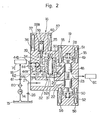
- FIG. 2 shows a detailed construction of the regulator valve 16 and the flow control valve 19.
- both valves 16 and 19 are provided in the same valve body 28.
- the regulator valve 16 comprises a valve spool 32, a puppot shaped valve member 36 and a relief valve 44.
- the valve spool 32 slides in a bore 30, thereby opening or closing a port 31 defined between the passage 18 and the drain passage 21.
- the valve spool 32 comprises a radially extending portion 45 and a head portion 32a.
- the head portion 32a has a small hole 42 therein.
- a chamber 46 is provided and defined between the radially extending portion 45 and an inner wall of the valve body.
- a compression coil spring 43 is located between the head portion 32a of the valve spool 32 and an inner wall of the valve body.
- the spring 43 biases the valve spool 32 in a direction which tends to close the port 31.
- the puppot shaped valve member 36 controls the flow of hydraulic fluid at a port 39 which connects a passage 34 with an oil chamber 35.
- a plunger 38 is fixed to the member 36, and slides in a bore 38a.
- a compression coil spring 40 is provided between the plunger 38 and an inner wall of the valve body. The spring 40 biases the valve member 36 in a manner which closes the port 39.
- a first solenoid 37 is positioned around the plunger 38 in the valve body 28 and functionally pulls the plunger 38 against the biasing force of the spring 40, whenever the solenoid 37 is actuated.
- An orifice 33 is provided in the passage 34, which communicates with the passage 18.
- a relief valve 44 is also provided in the passage 34 and comprises a check ball 44a and a spring 44b, which biases the ball 44a in a direction which tends to close a port 44c.
- the pressure in the chamber 46 exceeds a predetermined value, the ball 44a is displaced against the force of the spring 44b. In this condition, the oil in the passage 34 returns through the port 44c to the passage 18.
- the flow control valve 19 is provided in a position between the regulator valve 16 and the cylinder 6c of the driving pulley.
- the valve 19 comprises a valve spool 48, plungers 49 and 50, a second solenoid 55 and a third solenoid 56.
- the valve spool 48 controls the communication between the ports 20, 22 and 23.
- the plungers 49 and 50 are fixed to each end of the spool 48, respectively.
- a compression spring 51 biases the plunger 49 in a direction which tends to open the drain port 22.
- Another compression spring 52 is provided in a position opposite to that of the spring 51 and biases the plunger 50 in a direction which tends to close the drain port 22.
- the second solenoid 55 is provided around the plunger 49 in the valve body 28.
- the solenoid 55 pulls the plunger 49 by electromagnetic force against the biasing force of the spring 51.
- the third solenoid 56 is provided around the plunger 50 in the valve body 28. When the solenoid 56 is actuated, the solenoid 56 pulls the plunger 50 by electromagnetic force against the biasing force of the spring 52.
- the hydraulic fluid pump 14 pumps fluid from the reservoir 15 through the filter 60 and the check valve 61 and into the passage 62.
- the solenoid 37 pulls the plunger 38 against the biasing force of the .spring 40. Consequently, the pointed end of the valve member 36 lifts up, and the opening area of the port 39 increases.
- the chamber 35 communicates via the small hole 42 with the drain passage 21, the volume of the fluid drained increases when the opening area of the port 39 increases. In this condition, the hydraulic pressure in the chamber 46 decreases.
- valve spool 48 of the flow control valve 19 When electric current actuates both the second and third solenoids 55 and 56, the valve spool 48 of the flow control valve 19 is neutrally positioned, as shown in Figure 2, and corresponds to the second position 19B, as shown in Figure 1.
- the RPM ratios between the driving and driven pulleys are controlled by varying the amount of hydraulic fluid supplied to or drained from the hydraulic cylinder 6c of the driving pulley 6.
- the ECU 70 controls the regulator valve 16 and the flow control valve 19 in accordance with the signals detected by the various sensors.
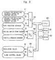
- Figure 3 shows that the ECU 70 functions as a digital computer and comprises a central processing unit (hereinafter referred to as CPU) 80 which carries out arithmetic and logic processing functions, an inter-face (hereinafter referred to as 1/F) 83, an analog-digital converter (hereinafter referred to as A/D) 84, a random-access memory 81 (hereinafter referred to as RAM) 81 which temporarily stores the calculated data of the CPU 80, a read-only memory (hereinafter referred to as ROM) 82 which stores a predetermined control program and arithmetic constants therein and a digital-analog converter (hereinafter referred to as D/A) 85.
- CPU central processing unit
- A/D analog-digital converter
- RAM random-access memory
- ROM read-only memory
- D/A digital-analog converter
- the I/F 83 receives an output signal from the sensor 71 corresponding to the rotational speed of the driving pulley 6 (RPM in ), an output signal from the sensor 72 corresponding to the rotational speed of the driven pulley 7 (RPM out ) and an output from the shift position sensor 76.
- the A/D 84 receives output signals from the coolant temperature sensor 73 and the throttle opening sensor 74.
- the CPU 80 a microprocessor, then compares the outputs received against any stored information and issues an output to the D/A 85 which subsequently outputs any appropriate instructions to the regulator valve 16 and the flow control valve 19.
- the ROM memory means 82 works in conjunction with the CPU data processing means 80 in the following manner:
- the ROM 82 stores a data map which includes the desired engine speed in a transient shifting condition, as shown in Figure 5, and data relating to the amount of throttle opening.
- the CPU data processing means 80 compares the actual operating conditions to the data stored in the ROM 82, and if appropriate, outputs a signal which results in the regulator valve 16 and the flow control valve 19 being controlled.
- Figure 4 illustrates a graph showing the relationship between the desired engine speed (RPM ) in a steady driving state and the amount of throttle opening ( ⁇ .
- the desired engine speed (RPM os ) is selected so that the amount of fuel consumed is a minimum.
- FIG. 5(a) illustrates a graph showing the relationship between a desired engine speed (RPM ot ) in a transient shifting condition of the engine and a time "t" occurring during the acceleration stage.
- Figure 5(b) illustrates a graph showing the relationship between the amount of throttle opening and a time "t” occurring during the acceleration stage.
- the throttle opening ( ⁇ ) increases from a value ⁇ 1 to a value ⁇ 2 when the time equals zero.
- the ECU 70 compares the engine speed RPM , , which corresponds to a throttle opening of ⁇ 1 , with the engine speed RPM ot2 , which corresponds to a throttle opening ⁇ 2 .
- RPM a is a constant and the magnitude of the difference between RPM os and RPM ot is compared to RPM . Then the desired engine speed in a transient acceleration shifting condition (RPM ot ) varies as indicated by the solid line shown in Figure 5(a). This variation is further discussed below.
- RPM ot corresponds to a previously calculated RPM ot , which is reinserted into equation (2) so that a progressive change in engine speed can be realized.
- Equation (2) results in a different engine speed approximately every 10m seconds; RPM is the desired engine speed at steady state conditions when the throttle opening is defined by ⁇ 1 ; C 1 and C 2 are constants. Note that when the time "t" is equal to t 1 , RPM ot increases to RPM ot3 and when the time "t" is equal to t 2 , RPM ot increases to RPM ot2 .
- Equation (4) results in a different engine speed approximately every 10m seconds;
- RPM os is the desired engine speed at steady state conditions when the present throttle opening is defined by ⁇ 1 ;
- D 1 and D 2 are constants; and part of the right side of equation (4) is defined by equation (5): D 1 and D 2 are determined so that the RPM ot on the left side of equation (4) can be gradually varied.
- FIG. 6 shows a flow chart illustrating the operation of the program according to the present invention.
- This program is an interruption program which is performed after a prescribed timing signal is issued.
- the ECU 70 commences the operation when the vehicle's main power switch is turned on.
- the first step 90 determines whether
- step 91 the desired engine speed during a transient shifting condition (RPM ot ) is calculated by the equation (4): If the program proceeded to step 92, a timer "Tm” is set to be zero. The timer “Tm” counts a clock pulse. The program then proceeds to step 93. In step 93, the ECU 70 reads the values, t 1 , B, C 1 and C 2 . Step 94 then determines whether the timer "Tm" is less than t 1 or not. If the timer "Tm" is less than t 1 , then the program proceeds to step 95.
- step 98 the desired engine speed during a transient condition (RPM ot ) is calculated by using the following equation:
- RPM os is the desired engine speed in a steady state condition when the present throttle opening is equal to e ;
- RPM' ot is the desired engine speed resulting from the previous calculation in step 98; and
- ⁇ RPM b is a constant. If
- FIG 7 (a) illustrates a graph showing the relationship between the desired engine speed during a transient deceleration shifting condition (RPM ot ) and a time "t”.
- Figure 7(b) illustrates a graph showing the relationship between an amount of throttle opening ( 6 ) and the time "t".
- the ECU 70 compares the engine speed RPM otl , which corresponds to the throttle opening ⁇ 1 , with the engine speed RPM ot2 , which corresponds to the throttle opening ⁇ 2 .
- Equation (7) results in a different engine speed approximately every 10 millisecond; RPM is the desired engine speed at steady state conditions when the throttle opening is defined by ⁇ 1 ; and E 1 and E 2 are constants.
- the engine speed (RPM e ) is utilized as a parameter of the program.
- the transmission ratio is defined by the following equations: where, e os is the desired transmission ratio in a steady state condition; and, where, e ot is the desired transmission ratio in a transient shifting condition.
- the actual transmission ratio "e” is calculated by the ratio (RPM out / RPM in ).
Landscapes
- Engineering & Computer Science (AREA)
- Mechanical Engineering (AREA)
- Chemical & Material Sciences (AREA)
- Combustion & Propulsion (AREA)
- Transportation (AREA)
- General Engineering & Computer Science (AREA)
- Automation & Control Theory (AREA)
- Control Of Transmission Device (AREA)
Applications Claiming Priority (2)
| Application Number | Priority Date | Filing Date | Title |
|---|---|---|---|
| JP58017550A JPS59144849A (ja) | 1983-02-07 | 1983-02-07 | 車両用無段変速機の制御方法 |
| JP17550/83 | 1983-02-07 |
Publications (2)
| Publication Number | Publication Date |
|---|---|
| EP0118184A1 true EP0118184A1 (de) | 1984-09-12 |
| EP0118184B1 EP0118184B1 (de) | 1988-05-11 |
Family
ID=11947020
Family Applications (1)
| Application Number | Title | Priority Date | Filing Date |
|---|---|---|---|
| EP84300494A Expired EP0118184B1 (de) | 1983-02-07 | 1984-01-26 | Verfahren zum Betätigen eines mit einem stufenlosen Getriebe vereinigten Motors |
Country Status (4)
| Country | Link |
|---|---|
| US (1) | US4594916A (de) |
| EP (1) | EP0118184B1 (de) |
| JP (1) | JPS59144849A (de) |
| DE (1) | DE3471144D1 (de) |
Cited By (7)
| Publication number | Priority date | Publication date | Assignee | Title |
|---|---|---|---|---|
| FR2570459A1 (fr) * | 1984-09-14 | 1986-03-21 | Nippon Seiko Kk | Appareil de reglage de transmission pour une transmission infiniment variable |
| EP0182616A1 (de) * | 1984-11-16 | 1986-05-28 | Fuji Jukogyo Kabushiki Kaisha | Steuerung für ein stufenloses Getriebe |
| EP0210663A3 (en) * | 1985-08-02 | 1987-11-11 | Kabushiki Kaisha Toyota Chuo Kenkyusho | Revolution speed ratio control system for a continuously variable transmission |
| EP0228817A3 (en) * | 1985-11-29 | 1987-11-11 | Kabushiki Kaisha Toyota Chuo Kenkyusho | Hydraulic control apparatus for stepless transmission |
| EP0127292B1 (de) * | 1983-05-23 | 1988-06-15 | Toyota Jidosha Kabushiki Kaisha | Verfahren zum Steuern eines Motors mit einem stufenlosen Getriebe |
| US5109730A (en) * | 1989-01-19 | 1992-05-05 | Deere & Company | Control system for shifting a gearbox |
| WO1994005934A1 (de) * | 1992-09-04 | 1994-03-17 | Zf Friedrichshafen Aktiengesellschaft | Vorrichtung zur regelung des übersetzungsverhältnisses eines stufenlosen getriebes |
Families Citing this family (16)
| Publication number | Priority date | Publication date | Assignee | Title |
|---|---|---|---|---|
| JPS60256661A (ja) * | 1984-06-01 | 1985-12-18 | Toyota Motor Corp | 車両用無段変速機の制御装置 |
| JPS6127357A (ja) * | 1984-07-18 | 1986-02-06 | Toyota Motor Corp | 車両用無段変速機の制御装置 |
| JPS61119856A (ja) * | 1984-09-25 | 1986-06-07 | Toyota Motor Corp | 無段変速機を備えた車両の駆動力制御装置 |
| JPS61278432A (ja) * | 1985-06-03 | 1986-12-09 | Toyota Motor Corp | 無段変速機の速度比制御方法 |
| EP0239365B1 (de) * | 1986-03-25 | 1990-12-05 | Fuji Jukogyo Kabushiki Kaisha | Steuerung für das Übersetzungsverhältnis eines stufenlosen Antriebes |
| JPS62227825A (ja) * | 1986-03-28 | 1987-10-06 | Fuji Heavy Ind Ltd | 無段変速機の制御装置 |
| JPH0765661B2 (ja) * | 1986-09-08 | 1995-07-19 | 日産自動車株式会社 | 無段変速機の変速制御装置 |
| JPH07102791B2 (ja) * | 1986-12-11 | 1995-11-08 | トヨタ自動車株式会社 | 車両用無段変速機の制御装置 |
| US5115395A (en) * | 1987-03-13 | 1992-05-19 | Borg-Warner Automotive, Inc. | Pulse width modulation technique |
| JPS6444394A (en) * | 1987-08-11 | 1989-02-16 | Honda Motor Co Ltd | Controller for non-stage transmission |
| JPH01108464A (ja) * | 1987-10-20 | 1989-04-25 | Honda Motor Co Ltd | 車両用無段変速機の変速制御方法 |
| JPH07117157B2 (ja) * | 1987-11-16 | 1995-12-18 | 本田技研工業株式会社 | 車両用無段変速機の変速制御方法 |
| JP2706790B2 (ja) * | 1988-11-30 | 1998-01-28 | スズキ株式会社 | 連続可変変速機の回転数制御装置 |
| US5006093A (en) * | 1989-02-13 | 1991-04-09 | Toyota Jidosha Kabushiki Kaisha | Hydraulic control apparatus for vehicle power transmitting system having continuously variable transmission |
| JP2006077642A (ja) * | 2004-09-08 | 2006-03-23 | Honda Motor Co Ltd | 船外機のエンジン回転数制御装置 |
| US7832297B2 (en) | 2005-04-19 | 2010-11-16 | Hewatt Chris B | Method and apparatus for gyroscopic propulsion |
Citations (6)
| Publication number | Priority date | Publication date | Assignee | Title |
|---|---|---|---|---|
| US3036426A (en) * | 1958-08-25 | 1962-05-29 | Citroen Sa Andre | Regulator means for driving automotive vehicles equipped with infinitely variable-speed drive |
| US3362262A (en) * | 1964-06-29 | 1968-01-09 | Citroen Sa Andre | Regulators for driving automotive vehicles equipped with infinitely variable-speed drve |
| GB1277825A (en) * | 1968-12-05 | 1972-06-14 | Daimler Benz Ag | Improvements relating to power units for vehicles |
| US3814224A (en) * | 1970-09-19 | 1974-06-04 | Zahnradfabrik Friedrichshafen | Fuel-supply control for automotive transmissions and the like |
| DE2239874B2 (de) * | 1971-09-01 | 1976-12-02 | General Motors Corp., Detroit, Mich. (V.St.A.) | Steuereinrichtung fuer einen kraftfahrzeugantrieb |
| GB2066919A (en) * | 1979-12-22 | 1981-07-15 | Automotive Prod Co Ltd | Clutch control apparatus |
Family Cites Families (3)
| Publication number | Priority date | Publication date | Assignee | Title |
|---|---|---|---|---|
| JPS5638416B2 (de) * | 1973-09-05 | 1981-09-07 | ||
| US4091690A (en) * | 1976-09-28 | 1978-05-30 | Aisin Seiki Kabushiki Kaisha | Method for controlling continuously variable drive ratio transmissions and a system therefor |
| FR2464853B1 (fr) * | 1979-09-12 | 1987-07-31 | Bosch Gmbh Robert | Installation de commande pour variateur de vitesse continu de vehicule automobile |
-
1983
- 1983-02-07 JP JP58017550A patent/JPS59144849A/ja active Granted
-
1984
- 1984-01-26 EP EP84300494A patent/EP0118184B1/de not_active Expired
- 1984-01-26 DE DE8484300494T patent/DE3471144D1/de not_active Expired
- 1984-01-30 US US06/574,737 patent/US4594916A/en not_active Expired - Lifetime
Patent Citations (6)
| Publication number | Priority date | Publication date | Assignee | Title |
|---|---|---|---|---|
| US3036426A (en) * | 1958-08-25 | 1962-05-29 | Citroen Sa Andre | Regulator means for driving automotive vehicles equipped with infinitely variable-speed drive |
| US3362262A (en) * | 1964-06-29 | 1968-01-09 | Citroen Sa Andre | Regulators for driving automotive vehicles equipped with infinitely variable-speed drve |
| GB1277825A (en) * | 1968-12-05 | 1972-06-14 | Daimler Benz Ag | Improvements relating to power units for vehicles |
| US3814224A (en) * | 1970-09-19 | 1974-06-04 | Zahnradfabrik Friedrichshafen | Fuel-supply control for automotive transmissions and the like |
| DE2239874B2 (de) * | 1971-09-01 | 1976-12-02 | General Motors Corp., Detroit, Mich. (V.St.A.) | Steuereinrichtung fuer einen kraftfahrzeugantrieb |
| GB2066919A (en) * | 1979-12-22 | 1981-07-15 | Automotive Prod Co Ltd | Clutch control apparatus |
Cited By (8)
| Publication number | Priority date | Publication date | Assignee | Title |
|---|---|---|---|---|
| EP0127292B1 (de) * | 1983-05-23 | 1988-06-15 | Toyota Jidosha Kabushiki Kaisha | Verfahren zum Steuern eines Motors mit einem stufenlosen Getriebe |
| FR2570459A1 (fr) * | 1984-09-14 | 1986-03-21 | Nippon Seiko Kk | Appareil de reglage de transmission pour une transmission infiniment variable |
| EP0182616A1 (de) * | 1984-11-16 | 1986-05-28 | Fuji Jukogyo Kabushiki Kaisha | Steuerung für ein stufenloses Getriebe |
| EP0210663A3 (en) * | 1985-08-02 | 1987-11-11 | Kabushiki Kaisha Toyota Chuo Kenkyusho | Revolution speed ratio control system for a continuously variable transmission |
| EP0228817A3 (en) * | 1985-11-29 | 1987-11-11 | Kabushiki Kaisha Toyota Chuo Kenkyusho | Hydraulic control apparatus for stepless transmission |
| US4798561A (en) * | 1985-11-29 | 1989-01-17 | Kabushiki Kaisha Toyota Chuo Kenkyusho | Hydraulic control apparatus for stepless transmission |
| US5109730A (en) * | 1989-01-19 | 1992-05-05 | Deere & Company | Control system for shifting a gearbox |
| WO1994005934A1 (de) * | 1992-09-04 | 1994-03-17 | Zf Friedrichshafen Aktiengesellschaft | Vorrichtung zur regelung des übersetzungsverhältnisses eines stufenlosen getriebes |
Also Published As
| Publication number | Publication date |
|---|---|
| JPS59144849A (ja) | 1984-08-20 |
| DE3471144D1 (en) | 1988-06-23 |
| JPH0335536B2 (de) | 1991-05-28 |
| EP0118184B1 (de) | 1988-05-11 |
| US4594916A (en) | 1986-06-17 |
Similar Documents
| Publication | Publication Date | Title |
|---|---|---|
| EP0118184B1 (de) | Verfahren zum Betätigen eines mit einem stufenlosen Getriebe vereinigten Motors | |
| US4663990A (en) | Method for controlling continuously variable transmission | |
| US4584907A (en) | Method for controlling a rate of changing an RPM ratio in a continuously variable transmission | |
| US4764156A (en) | System for controlling transmission ratio of a continuously variable transmission for a motor vehicle | |
| EP0061735B1 (de) | Steuerungssystem für stufenlos regelbare Riemengetriebe | |
| US4716790A (en) | Continuously variable transmission control system responsive to passenger compartment noise or vibration | |
| EP0140355B1 (de) | Verfahren und Vorrichtung zum Steuern eines hydraulisch betätigbaren stufenlosen Keilriemengetriebes | |
| US4782934A (en) | Control system for a continuously variable transmission | |
| US4727771A (en) | Method for controllig a controlling a continuously variable transmission | |
| EP0127292B1 (de) | Verfahren zum Steuern eines Motors mit einem stufenlosen Getriebe | |
| EP0225747B1 (de) | Steuereinrichtung für den Leitungsdruck eines stufenlos verstellbaren Getriebes | |
| EP0117069B1 (de) | Steuermethode für ein stufenlos regelbares Getriebe | |
| EP0092228A1 (de) | Verfahren und Vorrichtung zum Verstellen des Übersetzungsverhältnisses eines stufenlosen Getriebes | |
| EP0421202B1 (de) | Verfahren zur Steuerung eines stufenlos arbeitenden Getriebes | |
| US4803900A (en) | Transmission ratio control system for a continuously variable transmission | |
| US4619629A (en) | Hydraulic pressure control apparatus for a continuously variable transmission | |
| US5820514A (en) | Continuously variable transmission controller and control method | |
| US5114383A (en) | Apparatus for controlling continuous variable transmission | |
| US4601680A (en) | Control apparatus for use of a continuously variable transmission | |
| US4747325A (en) | Transmission ratio control system for a continuously variable transmission | |
| US4759236A (en) | System for controlling the pressure of oil in a system for a continuously variable transmission | |
| EP0228263B1 (de) | Steuervorrichtung für ein stufenlos regelbares Getriebe | |
| US4708031A (en) | Transmission ratio control system for a continuously variable transmission | |
| EP0233781B1 (de) | Steuerung des Übersetzungsverhältnisses eines stufenlos regelbaren Antriebes | |
| US4942783A (en) | Transmission ration control system for a continuously variable transmission |
Legal Events
| Date | Code | Title | Description |
|---|---|---|---|
| PUAI | Public reference made under article 153(3) epc to a published international application that has entered the european phase |
Free format text: ORIGINAL CODE: 0009012 |
|
| AK | Designated contracting states |
Designated state(s): DE FR GB |
|
| 17P | Request for examination filed |
Effective date: 19840809 |
|
| GRAA | (expected) grant |
Free format text: ORIGINAL CODE: 0009210 |
|
| AK | Designated contracting states |
Kind code of ref document: B1 Designated state(s): DE FR GB |
|
| REF | Corresponds to: |
Ref document number: 3471144 Country of ref document: DE Date of ref document: 19880623 |
|
| ET | Fr: translation filed | ||
| PLBE | No opposition filed within time limit |
Free format text: ORIGINAL CODE: 0009261 |
|
| STAA | Information on the status of an ep patent application or granted ep patent |
Free format text: STATUS: NO OPPOSITION FILED WITHIN TIME LIMIT |
|
| 26N | No opposition filed | ||
| REG | Reference to a national code |
Ref country code: GB Ref legal event code: 746 |
|
| REG | Reference to a national code |
Ref country code: FR Ref legal event code: DL |
|
| REG | Reference to a national code |
Ref country code: GB Ref legal event code: IF02 |
|
| PGFP | Annual fee paid to national office [announced via postgrant information from national office to epo] |
Ref country code: FR Payment date: 20030110 Year of fee payment: 20 |
|
| PGFP | Annual fee paid to national office [announced via postgrant information from national office to epo] |
Ref country code: GB Payment date: 20030122 Year of fee payment: 20 |
|
| PGFP | Annual fee paid to national office [announced via postgrant information from national office to epo] |
Ref country code: DE Payment date: 20030206 Year of fee payment: 20 |
|
| PG25 | Lapsed in a contracting state [announced via postgrant information from national office to epo] |
Ref country code: GB Free format text: LAPSE BECAUSE OF EXPIRATION OF PROTECTION Effective date: 20040125 |
|
| REG | Reference to a national code |
Ref country code: GB Ref legal event code: PE20 |