EP0118192A1 - Fibre optique monomode avec polarisation - Google Patents
Fibre optique monomode avec polarisation Download PDFInfo
- Publication number
- EP0118192A1 EP0118192A1 EP84300553A EP84300553A EP0118192A1 EP 0118192 A1 EP0118192 A1 EP 0118192A1 EP 84300553 A EP84300553 A EP 84300553A EP 84300553 A EP84300553 A EP 84300553A EP 0118192 A1 EP0118192 A1 EP 0118192A1
- Authority
- EP
- European Patent Office
- Prior art keywords
- region
- optical fiber
- central core
- cladding
- core region
- Prior art date
- Legal status (The legal status is an assumption and is not a legal conclusion. Google has not performed a legal analysis and makes no representation as to the accuracy of the status listed.)
- Granted
Links
- 239000013307 optical fiber Substances 0.000 title claims abstract description 19
- 239000000835 fiber Substances 0.000 claims abstract description 65
- 238000005253 cladding Methods 0.000 claims abstract description 47
- 230000010287 polarization Effects 0.000 claims abstract description 35
- 230000005641 tunneling Effects 0.000 claims abstract description 10
- 230000002238 attenuated effect Effects 0.000 claims abstract description 4
- VYPSYNLAJGMNEJ-UHFFFAOYSA-N Silicium dioxide Chemical compound O=[Si]=O VYPSYNLAJGMNEJ-UHFFFAOYSA-N 0.000 claims description 35
- 229910052681 coesite Inorganic materials 0.000 claims description 23
- 229910052906 cristobalite Inorganic materials 0.000 claims description 23
- 229910052682 stishovite Inorganic materials 0.000 claims description 23
- 229910052905 tridymite Inorganic materials 0.000 claims description 23
- 239000000377 silicon dioxide Substances 0.000 claims description 9
- 238000005452 bending Methods 0.000 claims description 7
- ZOXJGFHDIHLPTG-UHFFFAOYSA-N Boron Chemical compound [B] ZOXJGFHDIHLPTG-UHFFFAOYSA-N 0.000 claims description 4
- 229910052796 boron Inorganic materials 0.000 claims description 4
- 230000000644 propagated effect Effects 0.000 claims description 3
- 229910052732 germanium Inorganic materials 0.000 claims description 2
- GNPVGFCGXDBREM-UHFFFAOYSA-N germanium atom Chemical compound [Ge] GNPVGFCGXDBREM-UHFFFAOYSA-N 0.000 claims description 2
- 239000002019 doping agent Substances 0.000 claims 2
- BHEPBYXIRTUNPN-UHFFFAOYSA-N hydridophosphorus(.) (triplet) Chemical compound [PH] BHEPBYXIRTUNPN-UHFFFAOYSA-N 0.000 claims 1
- 230000001902 propagating effect Effects 0.000 claims 1
- 239000010410 layer Substances 0.000 description 24
- 239000000758 substrate Substances 0.000 description 7
- 230000008033 biological extinction Effects 0.000 description 2
- 230000008878 coupling Effects 0.000 description 2
- 238000010168 coupling process Methods 0.000 description 2
- 238000005859 coupling reaction Methods 0.000 description 2
- 230000007423 decrease Effects 0.000 description 2
- 238000003780 insertion Methods 0.000 description 2
- 230000037431 insertion Effects 0.000 description 2
- 238000004519 manufacturing process Methods 0.000 description 2
- 238000000034 method Methods 0.000 description 2
- 230000003287 optical effect Effects 0.000 description 2
- 238000001069 Raman spectroscopy Methods 0.000 description 1
- 230000009471 action Effects 0.000 description 1
- 230000002411 adverse Effects 0.000 description 1
- 230000008901 benefit Effects 0.000 description 1
- 230000005540 biological transmission Effects 0.000 description 1
- 239000012792 core layer Substances 0.000 description 1
- 230000003247 decreasing effect Effects 0.000 description 1
- 238000000151 deposition Methods 0.000 description 1
- 238000009826 distribution Methods 0.000 description 1
- 230000000694 effects Effects 0.000 description 1
- 230000005284 excitation Effects 0.000 description 1
- 238000012986 modification Methods 0.000 description 1
- 230000004048 modification Effects 0.000 description 1
Images

Classifications
-
- C—CHEMISTRY; METALLURGY
- C03—GLASS; MINERAL OR SLAG WOOL
- C03C—CHEMICAL COMPOSITION OF GLASSES, GLAZES OR VITREOUS ENAMELS; SURFACE TREATMENT OF GLASS; SURFACE TREATMENT OF FIBRES OR FILAMENTS MADE FROM GLASS, MINERALS OR SLAGS; JOINING GLASS TO GLASS OR OTHER MATERIALS
- C03C3/00—Glass compositions
- C03C3/04—Glass compositions containing silica
- C03C3/06—Glass compositions containing silica with more than 90% silica by weight, e.g. quartz
-
- G—PHYSICS
- G02—OPTICS
- G02B—OPTICAL ELEMENTS, SYSTEMS OR APPARATUS
- G02B6/00—Light guides; Structural details of arrangements comprising light guides and other optical elements, e.g. couplings
- G02B6/24—Coupling light guides
- G02B6/26—Optical coupling means
- G02B6/28—Optical coupling means having data bus means, i.e. plural waveguides interconnected and providing an inherently bidirectional system by mixing and splitting signals
- G02B6/2804—Optical coupling means having data bus means, i.e. plural waveguides interconnected and providing an inherently bidirectional system by mixing and splitting signals forming multipart couplers without wavelength selective elements, e.g. "T" couplers, star couplers
-
- G—PHYSICS
- G02—OPTICS
- G02B—OPTICAL ELEMENTS, SYSTEMS OR APPARATUS
- G02B6/00—Light guides; Structural details of arrangements comprising light guides and other optical elements, e.g. couplings
- G02B6/10—Light guides; Structural details of arrangements comprising light guides and other optical elements, e.g. couplings of the optical waveguide type
- G02B6/105—Light guides; Structural details of arrangements comprising light guides and other optical elements, e.g. couplings of the optical waveguide type having optical polarisation effects
Definitions
- the present invention relates to a single-mode single-polarization (SMSP) optical fibers.
- SMSP single-mode single-polarization
- Optical waveguides capable of transmitting power with only one direction of polarization are desirable in many different applications, such as fiber sensors, in-line fiber devices, Raman lasers, and the like.
- an ordinary axially symmetrical single-mode fiber is a "two- mode" fiber because two orthogonally polarized HE modes can be propagated in it. This fact results in the instability of the polarization state of the propagated mode when geometrical or dielectric perturbations exist in the fiber.
- polarization-preserving fibers as distinguished from single polarization fibers, have been developed, where these fibers may be categorized into three basic types; (1) elliptical-core fibers, (2) stress-induced birefringent fibers, and (3) side-pit fibers.
- U. S. Patent 4,274,854 issued to W. Pleibel et al on June 23, 1981 discloses a prior art method of fabricating a polarization-preserving optical fiber which produces a stress-induced birefringence therein.
- the method includes depositing the cladding layers and the core layer within a specially-shaped substrate tube, collapsing the resultant product into a preform and drawing a fiber therefrom.
- the difference in thermal expansion among the various layers combined with their inherent non- circularity, provide the stress-induced birefringence and hence the polarization-preserving properties of the resultant optical fiber.
- the two orthogonally polarized HEn modes have cutoff wavelengths which differ so that in a certain narrow frequency range one mode is attenuated while the other is transmitted.
- both polarizations propagate and the fiber will preserve linear polarization along both principal axes.
- the effective birefringence is geometrical in nature and is controlled by the index difference between the core, the cladding, and the side pits.
- the predicted single-polarization bandwidth is about 2.5%. It was suggested by Okoshi et al that for a practical single-polarization fiber a relative index difference of approximately 2% would be required.
- stress-induced birefringence is utilized to split the two polarizations of the fundamental mode and a cladding structure is included which attenuates one polarization by tunneling.
- An in-line fiber polarizer can be formed in accordance with the present invention which has significantly low insertion loss, low coupling loss and high extinction ratio.
- a polarizer may be employed, for example, in a fiber isolator, multiplexer, filter, tunable optical fiber, or fiber attenuator.
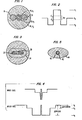
- FIG. 1 illustrates a cross-sectional view of a fiber polarizer formed in accordance with the present invention.
- a core region 10 is surrounded by a cladding layer 12, and a pair of stress lobes 14 and 16 are disposed, one on each side of cladding layer 12 in a silica substrate 18.
- core region 10, cladding layer 12, and stress lobes 14 and 16 are illustrated as having circular cross-sections, it is to be understood that each component may have an alternative cross-sectional shape, for example, elliptical, and remain within the scope of the present invention.
- core region 10 may comprise germanium-doped Si0 2' cladding layer 12 may comprise flourine-doped Si0 2 , and stress lobes 14 and 16 may comprise boron/germanium-doped Si0 2 .
- the refractive index of cladding layer 12, denoted n 2 , and the refractive index of silica substrate 18, denoted n 3 must be less than the refractive index, n l , of core 10, and, in particular, n 2 ⁇ n 3 ⁇ n l .
- the refractive index of stress lobes 14 and 16 may be the same as or less than that of substrate 18. If the refractive index of stress lobes 14 and 16 is greater than that of substrate 18, tunneling will take place into the stress lobes.
- a refractive index profile illustrated in FIG. 2 is helpful in explaining the basic principle of operation of a fiber polarizer formed in accordance with the present invention.
- the profile illustrates three separate refractive indices where n l >n 3 >n 2 , and the guided polarization of the fundamental mode is denoted n 11 and the unguided polarization is denoted n 1 .
- the guided polarization n 11 is split from the unguided polarization n 1 by the above-defined amount 6n, the stress-induced birefringence.
- 6n can be approximately equal to 10% of n 3 -n l , or approximately 5x10 -4 .
- birefringence is directly related to bandwidth, where a larger 6n results in a wider operational bandwidth for the fiber polarizer.
- the stress induced by stress lobes 14 and 16 sufficiently splits the two polarizations so as to raise guided polarization n 11 above the refractive index n 3 of substrate 18, while forcing unguided polarization n l to drop below the refractive index n 3 and attenuate through tunneling.
- some birefringence will exist outside core region 10 which acts to reduce the operable bandwidth of the polarizer.
- the birefringence decreases with distance from core 10 so that maximum bandwidth requires a large inner cladding 12.
- this inner cladding region 12 should be narrow for rapid tunneling loss of the undesired polarization. Therefore, a trade-off exists between providing rapid tunneling loss and providing a large bandwidth.
- FIG. 3 A cross-sectional view of an alternative fiber polarizer which provides both large bandwidth and rapid tunneling loss is illustrated in FIG. 3.
- a core region 30 is surrounded by a highly elliptical inner cladding layer 32 which is in turn surrounded by an outer cladding layer 34.
- outer cladding layer 34 has an elliptical cross-section.
- core region 30 may comprise Si0 2' inner cladding layer 32 may comprise boron doped Si0 2' and outer cladding layer 34 may comprise fluorine-doped Si0 2 .
- the refractive indices of inner cladding layer 32 and outer cladding layer 34 denoted n 2 and n 3 , respectively, must be less than the refractive index, n l , of core region 30, and in particular n 2 ⁇ n 3 ⁇ n l .
- Inner cladding layer 32 has a sufficiently high ellipticity such that the minor axis of inner cladding layer 32, is essentially equal to the radius of core region 30. This large ellipticity of inner cladding layer 32 thereby induces a large stress on the fiber, sufficient to significantly separate the two polarizations of the fundamental mode, denoted n 11 and n 1 .
- inner cladding 32 in association with its highly elliptical cross-section, provides both the necessary low refractive index cladding and stress-induced birefringence to form a fiber polarizer in accordance with the present invention.
- the embodiment as illustrated has the advantage that the birefringence falls off very quickly outside core region 30 along the minor axis of inner cladding 32 and, therefore, the operable bandwidth is little affected by the presence of birefringence outside core region 30.
- core region 30 may comprise Si02
- inner cladding layer 32 may comprise boron-doped Si0 2'
- outer cladding layer 34 may comprise flourine-doped Si0 2 .
- the extinction ratio of a 1.2m section of fiber polarizer formed in accordance with the present invention is approximately 30dB at 633nm, where insertion loss is approximately 2.3dB, including end reflections and coupling loss.
- FIG. 4 The refractive index profile for a fiber polarizer formed in accordance with the embodiment of the present invention illustrated in FIG. 3 is shown in FIG. 4, where both the profile related to the major axis of the fiber and the profile related to the minor axis of the fiber are illustrated.
- the fiber comprises a doped (for example, germanium) silica core region 40, a low index cladding layer 42, and a non-circular outer cladding region 44, where outer region 44 may comprise boron-doped Si0 2 and cladding layer 42 may comprise flourine-doped Si0 2 .
- tunneling occurs between core region 40 and outer region 44.
- Cladding layer 42 functions to decrease the loss at longer wavelengths due to the presence of boron in the outer region 44.
- FIG. 6 A graph illustrating fiber output power versus wavelength for unpolarized white light excitation of a single-mode single-polarization fiber formed in accordance with the present invention is illustrated in FIG. 6.
- Curve A is associated with the transmitted polarization of propagation n 11 and curve B is associated with the suppressed polarization of propagation n l .
- Curve B is associated with the suppressed polarization of propagation n l .
- the two polarizations of the fundamental mode begin to split significantly, and when the input light has a wavelength of approximately 0.56 micrometers, the undesired polarization of propagation is suppressed, that is, has negligible output power.
- This split between the two polarizations of the fundamental mode exists over the bandwidth, C, illustrated in FIG. 6, thereby yielding a fiber polarizer comprising a significantly larger bandwidth than available with prior art devices.
- the fiber polarizer may be bent to include a predetermined bending radius or wrapped around a rod of predetermined diameter, where the operating wavelength of the polarizer shifts as a function of the bending radius. Therefore, a fiber polarizer may be tuned to a desired wavelength of operation merely by bending, or wrapping, the fiber polarizer.
- the transmission data of FIG. 6 were obtained with four turns of a polarizer fiber, formed in accordance with the present invention, wound with a 1.5 cm bending radius. The same fiber may be wound on a 14 cm diameter rod, and will function as a polarizer between 0.6 and 0.64 ⁇ m.
Landscapes
- Physics & Mathematics (AREA)
- General Physics & Mathematics (AREA)
- Optics & Photonics (AREA)
- Chemical & Material Sciences (AREA)
- Chemical Kinetics & Catalysis (AREA)
- Engineering & Computer Science (AREA)
- Life Sciences & Earth Sciences (AREA)
- General Chemical & Material Sciences (AREA)
- Geochemistry & Mineralogy (AREA)
- Materials Engineering (AREA)
- Organic Chemistry (AREA)
- Optical Fibers, Optical Fiber Cores, And Optical Fiber Bundles (AREA)
- Glass Compositions (AREA)
Applications Claiming Priority (2)
| Application Number | Priority Date | Filing Date | Title |
|---|---|---|---|
| US06/464,059 US4515436A (en) | 1983-02-04 | 1983-02-04 | Single-mode single-polarization optical fiber |
| US464059 | 2009-05-11 |
Publications (2)
| Publication Number | Publication Date |
|---|---|
| EP0118192A1 true EP0118192A1 (fr) | 1984-09-12 |
| EP0118192B1 EP0118192B1 (fr) | 1991-08-28 |
Family
ID=23842379
Family Applications (1)
| Application Number | Title | Priority Date | Filing Date |
|---|---|---|---|
| EP84300553A Expired - Lifetime EP0118192B1 (fr) | 1983-02-04 | 1984-01-30 | Fibre optique monomode avec polarisation |
Country Status (5)
| Country | Link |
|---|---|
| US (1) | US4515436A (fr) |
| EP (1) | EP0118192B1 (fr) |
| JP (1) | JPS59148005A (fr) |
| KR (1) | KR910000718B1 (fr) |
| DE (1) | DE3484964D1 (fr) |
Cited By (1)
| Publication number | Priority date | Publication date | Assignee | Title |
|---|---|---|---|---|
| AU593421B2 (en) * | 1987-04-28 | 1990-02-08 | Hughes Aircraft Company | An improved polarization preserving optical fiber and method of manufacturing |
Families Citing this family (35)
| Publication number | Priority date | Publication date | Assignee | Title |
|---|---|---|---|---|
| JPS59202401A (ja) * | 1983-05-02 | 1984-11-16 | Sumitomo Electric Ind Ltd | 光フアイバおよびその製造方法 |
| EP0129972B1 (fr) * | 1983-05-26 | 1987-11-19 | Plessey Overseas Limited | Dispositifs optiques de détection à lumière polarisée |
| US4607912A (en) * | 1983-12-07 | 1986-08-26 | The United States Of America As Represented By The Secretary Of The Navy | In-line optical fiber polarizer |
| US4681399A (en) * | 1984-10-01 | 1987-07-21 | Polaroid Corporation | Stressed core optical fiber and method |
| US4723828A (en) * | 1984-11-09 | 1988-02-09 | Northern Telecom Limited | Bandwidth enhancement of multimode optical transmisson lines |
| US4664473A (en) * | 1985-04-01 | 1987-05-12 | Corning Glass Works | Optical fiber formed of MgO--Al2 O3 --SiO2 glass |
| GB2209846B (en) * | 1987-09-17 | 1992-03-04 | Pirelli General Plc | Optical fibre wavelength filter having two cores |
| JPH01237507A (ja) * | 1987-12-04 | 1989-09-22 | Nippon Telegr & Teleph Corp <Ntt> | 絶対単一偏波光ファイバ |
| US4830463A (en) * | 1988-02-08 | 1989-05-16 | American Telephone And Telegraph Company, At&T Bell Laboratories | Article comprising silica-based glass containing aluminum and phorphorus |
| EP0346723A1 (fr) * | 1988-06-14 | 1989-12-20 | The Boeing Company | Procédé et dispositif de préparation d'une fibre optique revêtue à section transversale façonnée |
| US5056888A (en) * | 1989-07-17 | 1991-10-15 | Minnesota Mining And Manufacturing Company | Single-mode, single-polarization optical fiber |
| US5074642A (en) * | 1989-11-14 | 1991-12-24 | Hicks John W | Multifiber endoscope with fibers having different indices of refraction |
| US5452394A (en) * | 1994-02-24 | 1995-09-19 | Huang; Hung-Chia | Practical circular-polarization maintaining optical fiber |
| GB9703078D0 (en) * | 1997-02-14 | 1997-04-02 | Univ Southampton | Optical fibre and optical fibre device |
| US6157763A (en) * | 1998-01-28 | 2000-12-05 | Sdl, Inc. | Double-clad optical fiber with improved inner cladding geometry |
| US6778747B1 (en) | 1998-09-09 | 2004-08-17 | Corning Incorporated | Radially varying and azimuthally asymmetric optical waveguide fiber |
| US6229937B1 (en) | 1998-09-17 | 2001-05-08 | Corning Incorporated | Circularly polarized fiber in optical circuits |
| AU6137899A (en) * | 1998-09-17 | 2000-04-03 | Corning Incorporated | Circularly polarized fiber in optical circuits |
| US6724528B2 (en) | 2001-02-27 | 2004-04-20 | The United States Of America As Represented By The Secretary Of The Navy | Polarization-maintaining optical fiber amplifier employing externally applied stress-induced birefringence |
| US6563995B2 (en) | 2001-04-02 | 2003-05-13 | Lightwave Electronics | Optical wavelength filtering apparatus with depressed-index claddings |
| AU2002318475A1 (en) * | 2001-06-19 | 2003-01-02 | Stockeryale, Inc. | Fiber optic possessing shear stress in core |
| US6909538B2 (en) | 2002-03-08 | 2005-06-21 | Lightwave Electronics | Fiber amplifiers with depressed cladding and their uses in Er-doped fiber amplifiers for the S-band |
| US6970631B2 (en) | 2002-06-05 | 2005-11-29 | Lightwave Electronics | Suppression of cladding mode loss in fiber amplifiers with distributed suppression of amplified spontaneous emission (ASE) |
| US6995900B2 (en) * | 2003-01-21 | 2006-02-07 | Jds Uniphase Corporation | Method of making a short-pass fiber with controlled cut-off wavelength |
| US6744939B2 (en) * | 2002-05-20 | 2004-06-01 | Fitel Usa Corp. | Polarization maintaining optical fiber connector and method of tuning (PM connector) |
| US20040258340A1 (en) * | 2003-06-19 | 2004-12-23 | Paolucci Dora M. | Radiation tuned wavelength filtering device |
| US20040258341A1 (en) * | 2003-06-19 | 2004-12-23 | Paolucci Dora M. | Optical waveguide with radiation-tuned birefringence |
| US7724422B2 (en) * | 2004-01-30 | 2010-05-25 | Nufern | Method and apparatus for providing light having a selected polarization with an optical fiber |
| US20050226580A1 (en) * | 2004-04-08 | 2005-10-13 | Samson Bryce N | Optical fiber for handling higher powers |
| US7272287B2 (en) * | 2005-05-11 | 2007-09-18 | Fitel Usa Corp | Optical fiber filter for suppression of amplified spontaneous emission |
| US7770869B2 (en) * | 2006-05-18 | 2010-08-10 | Tt Technologies, Inc. | Portable winch |
| US20100247912A1 (en) * | 2009-03-24 | 2010-09-30 | Gapontsev Valentin P | Method for Manufacturing LMA Optical Preforms and Fibers |
| US20100284054A1 (en) * | 2009-05-08 | 2010-11-11 | Honeywell International Inc. | Modulation of unpolarized light |
| US8434330B2 (en) * | 2009-10-22 | 2013-05-07 | Ofs Fitel, Llc | Techniques for manufacturing birefringent optical fiber |
| US8369672B2 (en) * | 2010-04-27 | 2013-02-05 | Verrillon, Inc. | Single-polarization fiber |
Citations (4)
| Publication number | Priority date | Publication date | Assignee | Title |
|---|---|---|---|---|
| EP0032390A2 (fr) * | 1980-01-11 | 1981-07-22 | Hitachi, Ltd. | Procédé pour la fabrication d'une préforme pour une fibre optique |
| DE3123607A1 (de) * | 1980-06-18 | 1982-04-15 | International Standard Electric Corp., 10022 New York, N.Y. | Optischer monomode-wellenleiter in form einer glasfaser mit spannungsdoppelbrechung |
| DE3035153A1 (de) * | 1980-09-18 | 1982-04-22 | Licentia Patent-Verwaltungs-Gmbh, 6000 Frankfurt | Verfahren und anordnung zur stabilisierung eines polarisationszustandes in einer lichtleitfaser |
| EP0067017A1 (fr) * | 1981-05-29 | 1982-12-15 | Hitachi, Ltd. | Fibre optique qui conserve le plan de la polarisation et procédure de sa fabrication |
Family Cites Families (16)
| Publication number | Priority date | Publication date | Assignee | Title |
|---|---|---|---|---|
| US3535017A (en) * | 1968-01-08 | 1970-10-20 | Bell Telephone Labor Inc | Optical fiber waveguide structures |
| US3659916A (en) * | 1970-07-28 | 1972-05-02 | Bell Telephone Labor Inc | Single-mode dielectric waveguide |
| US3997241A (en) * | 1973-06-07 | 1976-12-14 | Hitachi, Ltd. | Optical waveguide transmitting light wave energy in single mode |
| JPS5250246A (en) * | 1975-10-20 | 1977-04-22 | Hitachi Ltd | Light transmitting line |
| JPS5258547A (en) * | 1975-11-10 | 1977-05-14 | Hitachi Ltd | Light transmission fiber |
| US4134642A (en) * | 1976-04-16 | 1979-01-16 | Northern Telecom Limited | Optical fibre with increased security |
| DE2635656A1 (de) * | 1976-08-07 | 1978-02-09 | Jenaer Glaswerk Schott & Gen | Faseroptische systeme mit uebersprecheffekten |
| US4106847A (en) * | 1976-09-07 | 1978-08-15 | Bell Telephone Laboratories, Incorporated | Noncircular symmetric optical fiber waveguide having minimum modal dispersion |
| DE2735312C2 (de) * | 1977-08-05 | 1982-06-03 | Licentia Patent-Verwaltungs-Gmbh, 6000 Frankfurt | Monomodelichtleiter |
| US4274854A (en) * | 1978-01-13 | 1981-06-23 | Bell Telephone Laboratories, Incorporated | Polarization-preserving optical fiber |
| US4179189A (en) * | 1978-01-13 | 1979-12-18 | Bell Telephone Laboratories, Incorporated | Single polarization optical fibers and methods of fabrication |
| JPS5565909A (en) * | 1978-11-13 | 1980-05-17 | Nippon Telegr & Teleph Corp <Ntt> | Optical fiber |
| US4307938A (en) * | 1979-06-19 | 1981-12-29 | Andrew Corporation | Dielectric waveguide with elongate cross-section |
| US4395270A (en) * | 1981-04-13 | 1983-07-26 | Corning Glass Works | Method of fabricating a polarization retaining single-mode optical waveguide |
| US4478489A (en) * | 1981-04-13 | 1984-10-23 | Corning Glass Works | Polarization retaining single-mode optical waveguide |
| JPS5835503A (ja) * | 1981-08-27 | 1983-03-02 | Nippon Telegr & Teleph Corp <Ntt> | 零偏波分散単一直線偏波光フアイバ |
-
1983
- 1983-02-04 US US06/464,059 patent/US4515436A/en not_active Expired - Lifetime
-
1984
- 1984-01-30 DE DE8484300553T patent/DE3484964D1/de not_active Expired - Lifetime
- 1984-01-30 EP EP84300553A patent/EP0118192B1/fr not_active Expired - Lifetime
- 1984-02-01 KR KR1019840000453A patent/KR910000718B1/ko not_active Expired
- 1984-02-03 JP JP59017224A patent/JPS59148005A/ja not_active Expired - Lifetime
Patent Citations (4)
| Publication number | Priority date | Publication date | Assignee | Title |
|---|---|---|---|---|
| EP0032390A2 (fr) * | 1980-01-11 | 1981-07-22 | Hitachi, Ltd. | Procédé pour la fabrication d'une préforme pour une fibre optique |
| DE3123607A1 (de) * | 1980-06-18 | 1982-04-15 | International Standard Electric Corp., 10022 New York, N.Y. | Optischer monomode-wellenleiter in form einer glasfaser mit spannungsdoppelbrechung |
| DE3035153A1 (de) * | 1980-09-18 | 1982-04-22 | Licentia Patent-Verwaltungs-Gmbh, 6000 Frankfurt | Verfahren und anordnung zur stabilisierung eines polarisationszustandes in einer lichtleitfaser |
| EP0067017A1 (fr) * | 1981-05-29 | 1982-12-15 | Hitachi, Ltd. | Fibre optique qui conserve le plan de la polarisation et procédure de sa fabrication |
Non-Patent Citations (6)
| Title |
|---|
| ELECTRONICS LETTERS, vol. 17, no. 17, 1981 S. MITACHI et al. "Fluoride-glass-cladded optical fibres for mid-infra-red ray transmission", pages 591-592 * |
| ELECTRONICS LETTERS, vol. 18, no. 24, 1982 R.D. BIRCH et al. "Fabrication of polarisation-maintaining fibres using gas-phase etching", pages 1036-1038 * |
| IEEE TRANSACTIONS ON QUANTUM ELECTRONICS, vol. QE-18, no. 4, 1982 D.N. PAYNE et al. "Development of low- and high-birefringence optical fibers", pages 477-488 * |
| IEEE TRANSACTIONS ON QUANTUM ELECTRONICS, vol. QE-18, no. 4, 1982 K. OKAMOTO et al. "Linearly single polarization fibers with zero polarization mode dispersion", pages 496-503 * |
| NUCLEAR SCIENCE, vol. NS-25, no. 6, 1978 S. SHARE et al. "The effect of temperature on the response of class-clad optical waveguides to ionizing radiation", pages 1288-1292 * |
| SOVIET JOURNAL OF QUANTUM ELECTRONICS, vol. 11, no. 11, 1981 A. GUR'YANOV et al. "Polarization properties of single-mode fiber-optic waveguides with weak birefringence", pages 1509-1512 * |
Cited By (1)
| Publication number | Priority date | Publication date | Assignee | Title |
|---|---|---|---|---|
| AU593421B2 (en) * | 1987-04-28 | 1990-02-08 | Hughes Aircraft Company | An improved polarization preserving optical fiber and method of manufacturing |
Also Published As
| Publication number | Publication date |
|---|---|
| KR910000718B1 (ko) | 1991-01-31 |
| US4515436A (en) | 1985-05-07 |
| JPS59148005A (ja) | 1984-08-24 |
| DE3484964D1 (de) | 1991-10-02 |
| EP0118192B1 (fr) | 1991-08-28 |
| KR840007547A (ko) | 1984-12-08 |
Similar Documents
| Publication | Publication Date | Title |
|---|---|---|
| US4515436A (en) | Single-mode single-polarization optical fiber | |
| JP3410374B2 (ja) | クラッディング励起ファイバの構造 | |
| US4307938A (en) | Dielectric waveguide with elongate cross-section | |
| US7289687B2 (en) | Polarization-maintaining optical fiber | |
| US7711238B2 (en) | Optical fiber and optical fiber coupler, erbium-doped optical fiber amplifier, and optical waveguide using the same | |
| EP0319319B1 (fr) | Fibre optique à polarisation unique | |
| US4549781A (en) | Polarization-retaining single-mode optical waveguide | |
| JP2003515781A (ja) | 径を拡大した光導波路、グレーティングおよびレーザ | |
| EP0860733B1 (fr) | Filtre à guide d'onde optique auto-accordant | |
| US6463195B1 (en) | Method of manufacturing polarization-maintaining optical fiber coupler | |
| JP2007536578A (ja) | 中実型単一偏波ファイバ及び装置 | |
| US6088494A (en) | Aperiodic Mach-Zehnder optical filters | |
| US20060239610A1 (en) | Apparatus for propagating optical radiation | |
| RU2627018C1 (ru) | Радиационно-стойкий одномодовый световод с большим линейным двулучепреломлением для волоконно-оптического гироскопа | |
| JPS6236203B2 (fr) | ||
| Morishita et al. | In-line optical fibre filters using dispersive materials | |
| US5946432A (en) | Periodic mach-zehnder optical filters | |
| WO2002103411A2 (fr) | Procede servant a induire des proprietes optiques de contrainte de cisaillement ainsi que la reduction ou l'elimination de la birefringence accidentelle dans des materiaux a transmission optique | |
| Maseer et al. | Double-Bulge Mode-Mismatch fiber Interferometer with a Hybrid Waist Region: An Intracavity Filter and Sensing Element in Erbium-Doped Fiber Laser | |
| KR101968846B1 (ko) | 수모드 광섬유를 이용한 소형 무편광기 | |
| RU2223522C2 (ru) | Одномодовый однополяризационный световод | |
| Edvold et al. | High-birefringent and high-gain erbium-doped polarization-maintaining fiber | |
| JPH0350505A (ja) | 単一偏波光ファイバ | |
| Monteiro et al. | A spot reflection alignment system for fabrication of polarization‐maintaining optical fiber couplers | |
| Gambling et al. | Optical Fibre Sensors-Chapter 8: Principles and Components |
Legal Events
| Date | Code | Title | Description |
|---|---|---|---|
| PUAI | Public reference made under article 153(3) epc to a published international application that has entered the european phase |
Free format text: ORIGINAL CODE: 0009012 |
|
| AK | Designated contracting states |
Designated state(s): DE FR GB IT NL |
|
| 17P | Request for examination filed |
Effective date: 19850213 |
|
| 17Q | First examination report despatched |
Effective date: 19860227 |
|
| GRAA | (expected) grant |
Free format text: ORIGINAL CODE: 0009210 |
|
| AK | Designated contracting states |
Kind code of ref document: B1 Designated state(s): DE FR GB IT NL |
|
| REF | Corresponds to: |
Ref document number: 3484964 Country of ref document: DE Date of ref document: 19911002 |
|
| ET | Fr: translation filed | ||
| ITF | It: translation for a ep patent filed | ||
| PLBE | No opposition filed within time limit |
Free format text: ORIGINAL CODE: 0009261 |
|
| STAA | Information on the status of an ep patent application or granted ep patent |
Free format text: STATUS: NO OPPOSITION FILED WITHIN TIME LIMIT |
|
| 26N | No opposition filed | ||
| PGFP | Annual fee paid to national office [announced via postgrant information from national office to epo] |
Ref country code: FR Payment date: 20001218 Year of fee payment: 18 |
|
| PGFP | Annual fee paid to national office [announced via postgrant information from national office to epo] |
Ref country code: GB Payment date: 20001228 Year of fee payment: 18 |
|
| PGFP | Annual fee paid to national office [announced via postgrant information from national office to epo] |
Ref country code: NL Payment date: 20010109 Year of fee payment: 18 |
|
| REG | Reference to a national code |
Ref country code: GB Ref legal event code: IF02 |
|
| PG25 | Lapsed in a contracting state [announced via postgrant information from national office to epo] |
Ref country code: GB Free format text: LAPSE BECAUSE OF NON-PAYMENT OF DUE FEES Effective date: 20020130 |
|
| PG25 | Lapsed in a contracting state [announced via postgrant information from national office to epo] |
Ref country code: NL Free format text: LAPSE BECAUSE OF NON-PAYMENT OF DUE FEES Effective date: 20020801 |
|
| GBPC | Gb: european patent ceased through non-payment of renewal fee |
Effective date: 20020130 |
|
| PG25 | Lapsed in a contracting state [announced via postgrant information from national office to epo] |
Ref country code: FR Free format text: LAPSE BECAUSE OF NON-PAYMENT OF DUE FEES Effective date: 20020930 |
|
| NLV4 | Nl: lapsed or anulled due to non-payment of the annual fee |
Effective date: 20020801 |
|
| REG | Reference to a national code |
Ref country code: FR Ref legal event code: ST |
|
| PGFP | Annual fee paid to national office [announced via postgrant information from national office to epo] |
Ref country code: DE Payment date: 20030131 Year of fee payment: 20 |