EP0118200A2 - Diebstahlsicherungsalarmvorrichtung für Videokassettenrecorder - Google Patents
Diebstahlsicherungsalarmvorrichtung für Videokassettenrecorder Download PDFInfo
- Publication number
- EP0118200A2 EP0118200A2 EP84300628A EP84300628A EP0118200A2 EP 0118200 A2 EP0118200 A2 EP 0118200A2 EP 84300628 A EP84300628 A EP 84300628A EP 84300628 A EP84300628 A EP 84300628A EP 0118200 A2 EP0118200 A2 EP 0118200A2
- Authority
- EP
- European Patent Office
- Prior art keywords
- housing
- operative position
- lock
- abutment member
- cassette
- Prior art date
- Legal status (The legal status is an assumption and is not a legal conclusion. Google has not performed a legal analysis and makes no representation as to the accuracy of the status listed.)
- Withdrawn
Links
Images

Classifications
-
- G—PHYSICS
- G08—SIGNALLING
- G08B—SIGNALLING SYSTEMS, e.g. PERSONAL CALLING SYSTEMS; ORDER TELEGRAPHS; ALARM SYSTEMS
- G08B13/00—Burglar, theft or intruder alarms
- G08B13/02—Mechanical actuation
- G08B13/14—Mechanical actuation by lifting or attempted removal of hand-portable articles
- G08B13/149—Mechanical actuation by lifting or attempted removal of hand-portable articles with electric, magnetic, capacitive switch actuation
-
- G—PHYSICS
- G11—INFORMATION STORAGE
- G11B—INFORMATION STORAGE BASED ON RELATIVE MOVEMENT BETWEEN RECORD CARRIER AND TRANSDUCER
- G11B33/00—Constructional parts, details or accessories not provided for in the other groups of this subclass
- G11B33/005—Means for locking the disc or cassette receiving slot, e.g. dummy cassettes locked in the slot
-
- Y—GENERAL TAGGING OF NEW TECHNOLOGICAL DEVELOPMENTS; GENERAL TAGGING OF CROSS-SECTIONAL TECHNOLOGIES SPANNING OVER SEVERAL SECTIONS OF THE IPC; TECHNICAL SUBJECTS COVERED BY FORMER USPC CROSS-REFERENCE ART COLLECTIONS [XRACs] AND DIGESTS
- Y10—TECHNICAL SUBJECTS COVERED BY FORMER USPC
- Y10T—TECHNICAL SUBJECTS COVERED BY FORMER US CLASSIFICATION
- Y10T70/00—Locks
- Y10T70/50—Special application
- Y10T70/5009—For portable articles
Definitions
- This invention relates to anti-theft alarm devices for video cassette recorders.
- pressure mats have been provided to receive thereon video cassette recorders, such mats incorporating electrical circuits actuation of which is dependent upon the presence or otherwise of outside pressure on the mat.
- an alarm device associated with the circuit is deactivated because of the weight of the recorder.
- the state of the circuit is altered and the alarm is activated.
- Such mats as well as being clearly visible, rely for their operation upon the resiliency of the material of the mat which must be such as to effect a change in state of the circuit on removal of pressure therefrom.
- the continuous presence of a heavy machine in one position on the mat can cause compaction of the material of the mat such that the resiliency initially inherent therein is reduced or eliminated whereby the mat fails to operate on removal of the machine therefrom.
- anti-theft devices comprise housings for attachment to the body of the machine, said housings containing movement-sensitive switches which, on any displacement of the video cassette recorder from a normal rest position, are actuated to complete an electrical warning circuit.
- Such switches may be, for example, mercury tilt switches or hydroswitches.
- said housings may contain ultrasonic Doppler systems including transmitters and receivers so arranged that any interruption of the transmitted sound waves, be it by movement of the machine itself or as a result of the interference of a moving object remote from the machine, caus es actuation of a warning mechanism.
- an anti-theft alarm device for a video cassette recorder comprising a housing for location in the cassette-receiving mechanism of the recorder, an abutment member mounted in said housing and movable, by means of a control mechanism operable from externally of the housing, between an inoperative position within the housing and an operative position projecting from the housing, and a battery-operated, movement-sensitive electrical switching mechanism contained within said housing and including a switch movable between an inoperative position and an operative position, and a warning mechanism the circuit of which is completed on movement of said switch to its operative position, the arrangement being such that, on location of the housing in the cassette-receiving mechanism and with the abutment member in its operative position,'said member co-operates with the recorder to prevent removal of the housing from the cassette-receiving mechanism other than by actuation of said control mechanism to move the abutment member to its inoperative position and subsequent withdrawal of the device from said cassette-receiving mechanism.
- the housing is inserted into the cassette-receiving mechanism and is then moved into position within the machine equivalent to the 'play' position for a standard video cassette, the control mechanism having been operated to move the abutment member into a position projecting from the housing and engaging with an edge of, for example, the cassette-receiving mechanism.
- the cir- cuitof the electrical switching mechanism is open but is ⁇ primed for movement of the switch to its operative position. If the video cassette recorder is displaced from its rest position, the switch is moved to its operative position and the associated warning mechanism, which is preferably of an audible nature, is actuated.
- depression of the 'eject' control on the recorder will then present the housing for removal from the cassette-receiving mechanism but, because of the cooperation between the abutment member and the recorder, the housing cannot be removed without first of all retracting the abutment member by operation of the associated control mechanism.
- This control mechanism is preferably a key-operated lock and it will thus be appreciated that anyone, such as a potential thief, without the correct key cannot remove the alarm device nor can he deactivate it.
- the key-operated lock may include a movable member co-operating with the abutment member such that rotation of the key in the lock between a rest position and a displaced position effects displacement of said movable member and consequential movement of the abutment member between its inoperative position and its operative position.
- the abutment member is resiliently-biased towards its operative position such that said abutment member can be displaced from its operative position to its inoperative position by the application thereto of a force opposing the resilient bias and independently of actuation of the control mechanism.
- the movable member of the lock further co-operates with the electrical switching mechanism in such a manner that, with the lock in its rest position, the circuit of said switching mechanism is broken and with the lock in its displaced position, said circuit is primed for completion by the switch on subsequent movement of said switch from its inoperative position to its operative position.
- the circuit of the electrical switching mechanism may include a time delay such that said circuit cannot be completed by movement of the switch from its inoperative position to its operative position for a predetermined period after initial rotation of the lock to its displaced position.
- the key-hole of the lock projects inwardly of the housing from the front face of said housing, while the abutment member, in its operative position, projects downwardly through the bottom surface of the housing and co-operates with an edge of the cassette-receiving mechanism.
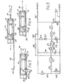
- the illustrated device comprises a housing indicated generally at 2 and including upper and lower portions 4,6.
- the housing 2 is of generally rectangular configuration and of dimensions substantially the same as those of a conventional video cassette, either of the Beta or VHS type, while the lower portion 6 of the housing is formed with conventionally- spaced capstan-receiving holes 8,10, all for reasons which will become apparent.
- a cylindrical lock 12 operated by a key 14, the key-hole end of the lock being substantially flush with the front face of the housing and the other end of the lock carrying a first projection 16 movable, on rotation of the key 14, between first and second positions within the housing.
- An abutment member 18 is mounted in the housing 2 to be pivotal about a substantially horizontal axis 20, the member 18 including a body portion 22 having a substantially vertical front face and an upwardly and rearwardly inclined lower face 24.
- the member 18 further includes a step-like upper portion 26, a lower surface of the upper step of which engages with the projection 16 of the lock 12.
- a spring 28 engages with the upper surface of the lower step of the portion 26 of the member 18 to urge said member towards an operative position shown in Figs. 1 and 3 in which the body portion 22 extends through a slot in the lower surface of the housing 2, said position being determined by engagement of the lower surface of the lower step of the portion 26 of the member 18 with the inner face of the bottom wall of the portion 6 of the housing 2.
- abutment member in its inoperative position within the housing 2, as in Figs. 2 and 4, or in its operative position projecting from the housing 2, as in Figs. 1 and 3, is determined by the position of the first projection 16, which position is in turn determined by the position of the lock 12.
- the arrangement so far described operates as follows.
- the tray of the cassette-receiving mechanism of a video cassette recorder is shown at 30 in Figs. 2 to 4 and the housing 2 is inserted into the tray 30 in the manner of a conventional cassette.
- the abutment member 18 can be in its inoperative position within the housing 2 as shown in Fig. 2.
- the key 14 is turned in the lock 12 whereby the abutment member 18 projects from the housing 2 to engage with an edge 32 of the tray 30 to prevent removal from the tray other than by reverse rotation of the key 14.
- the cassette-receiving mechanism, together with the housing 2 are then pushed into an operative 'play' or 'record' position within the recorder, the capstans of the recorder passing through the holes 8,10 in the lower portion 6 of the housing 2.
- the abutment member 18 may initially be in its operative position projecting from the housing 2, engagement of said member 18 with the tray 30 during loading of the housing 2 into the cassette-receiving mechanism biasing said member 18 into its inoperative position. As soon as the member 18 passes the edge 32 of the tray 30, said member springs into its operative position to engage with said edge and prevent removal of the housing 2 from the recorder other than by use of the key 14.
- an electrical switching mechanism powered by a battery 34 and including a movement-sensitive electric switch 'N', which may be, for example, a mercury tilt switch, hydroswitch or the like which reacts to any displacement thereof, and an audible electro-mechanical alarm 'A' actuation of which is dependent upon the condition of the switch 'N'.
- a movement-sensitive electric switch 'N' which may be, for example, a mercury tilt switch, hydroswitch or the like which reacts to any displacement thereof, and an audible electro-mechanical alarm 'A' actuation of which is dependent upon the condition of the switch 'N'.
- the switching mechanisms further includes an 'on-off' switch 'SW' located adjacent the other end of the lock 12, said end of the lock carrying, as well as the first projection 16, a further projection 36 adapted to co-operate with the switch 'SW'.
- the arrangement is such that, with the lock 12 in its first position as shown in Figs. 2 and 4, the projection 36 engages with the switch 'SW' to open said switch and de-activate the electrical switching mechanism. With the lock in its second position, as shown in Figs. 1 and 3, the switch 'SW' is closed to activate the circuit, actuation of the alarm 'A' then being dependent upon the condition of the switch 'N'.
- Fig. 5 which illustrates the circuit of the electrical switching mechanism and which is totally contained within the housing 2
- the components 'N', 'A' and 'SW' are as detailed above, with the contacts N/C of the switch 'N' being those normally closed with said switch in its normal undisturbed condition and the contacts N/0 being those normally open with the switch in said condition.
- the remaining components of the circuit are as follows:
- the circuit comprises four main sections, namely
- This stage of the circuit consists of a voltage divider comprising resistors Rl and R2 such that the divided voltage is fed into the NAND Schmitt gate IC 1 via resistor R3.
- the contacts N/C open - i.e. the tilt switch N actuated - the output from IC 1 is 'high', while the consequential closing of contacts N/0 to short- circuit resistor R2 results in the input to IC 1 being 'low', further causing the output from IC 1 to be 'high'.
- This stage of the circuit consists of resistor R4, capacitor 'C' and the NAND Schmitt gate IC 2 .
- capacitor 'C' charges up at a predetermined rate set by resistor R4, the voltage being fed to input IP 1 of gate IC 2 .
- IC 2 transmits any signal received from IC 1 , a 'high' on the input IP2 of IC 2 resulting in a 'low' at the output from IC 2 .
- the gate IC 3 merely inverts the output from IC 2 .
- This stage of the circuit consists of the thyristor 'Th' and resistor R7.
- the thyristor 'Th' starts conducting and the alarm 'A' is actuated.
- the resistor R8 is connected between the cathode of the thyristor and ground to prevent the thyristor from turning off as would otherwise happen because of the type of electromechanical alarm used.
- This stage of the circuit consists of resistors R9 and R10, Zener diode 'ZD', light-emitting diode 'LED' and the push-button 'PB'.
- resistor R9 acts as a load across the voltage supply and if the supply battery is still well charged, there will only be a slight voltage drop causing the diode 'ZD' to conduct and the diode 'LED' to light up. If the battery is low, the voltage drop is much bigger and at a certain predetermined level, the diode 'ZD' does not conduct and the diode 'LED' does not light up, indicating that the battery needs changing.
- the push button 'PB' and diode 'LED' can be seen to be mounted in the front wall of the housing 2.
- This alarm can only be switched off by ejecting the cassette-receiving mechanism to present the front wall of the housing 2 for insertion of the key 14 into the lock 12 whereby the switch 'SW' can be turned to the 'off' position. Turning of the switch 'SW' is accompanied by movement of the abutment member 18 to its inoperative position whereby the housing 2 can be withdrawn from the recorder.
- an anti-theft alarm device which is completely self-contained within a housing 2 and which can be located within a recorder so as not to be visible to a potential thief. Any unauthorised movement of the machine will activate the audible alarm which cannot be turned off without the correct key 14 for the lock 12.
Landscapes
- Physics & Mathematics (AREA)
- General Physics & Mathematics (AREA)
- Burglar Alarm Systems (AREA)
Applications Claiming Priority (2)
| Application Number | Priority Date | Filing Date | Title |
|---|---|---|---|
| GB8303028 | 1983-02-03 | ||
| GB8303028A GB8303028D0 (en) | 1983-02-03 | 1983-02-03 | Video theft alarm |
Publications (2)
| Publication Number | Publication Date |
|---|---|
| EP0118200A2 true EP0118200A2 (de) | 1984-09-12 |
| EP0118200A3 EP0118200A3 (de) | 1985-10-02 |
Family
ID=10537430
Family Applications (1)
| Application Number | Title | Priority Date | Filing Date |
|---|---|---|---|
| EP19840300628 Withdrawn EP0118200A3 (de) | 1983-02-03 | 1984-02-01 | Diebstahlsicherungsalarmvorrichtung für Videokassettenrecorder |
Country Status (3)
| Country | Link |
|---|---|
| US (1) | US4563673A (de) |
| EP (1) | EP0118200A3 (de) |
| GB (1) | GB8303028D0 (de) |
Cited By (6)
| Publication number | Priority date | Publication date | Assignee | Title |
|---|---|---|---|---|
| WO1985005725A1 (en) * | 1984-06-06 | 1985-12-19 | Tor Andersen | Means for cassette |
| EP0169353A3 (de) * | 1984-07-19 | 1986-03-19 | Reinhard Barnowsky | Vorrichtung zum Schutz von Video-Recordern vor unbefugter Benutzung |
| EP0205015A3 (de) * | 1985-06-08 | 1987-06-03 | Blaupunkt-Werke GmbH | Mechanische Diebstahl-Sicherung für elektronische Zusatzgeräte mit Kassetten-Laufwerk in Kraftfahrzeugen |
| US4964286A (en) * | 1987-12-10 | 1990-10-23 | Michael Poyer | Security device for a video recorder or player |
| GB2296597A (en) * | 1994-11-30 | 1996-07-03 | Terence Ronald Green | Anti-tamper device for a cassette recorder |
| EP0806770A1 (de) * | 1996-05-10 | 1997-11-12 | Terence Ronald Green | Vorrichtung zum Schutz gegen unbefugte Handhabung |
Families Citing this family (10)
| Publication number | Priority date | Publication date | Assignee | Title |
|---|---|---|---|---|
| SE456956B (sv) * | 1984-05-16 | 1988-11-14 | Lockia Ab | Saekerhetsanordning foer avspelningsapparater |
| US4628713A (en) * | 1985-03-29 | 1986-12-16 | Tape-Lock Company | Lock for video tape cassettes |
| US4800361A (en) * | 1987-07-13 | 1989-01-24 | Greif Jonathan D | Anti-theft alarm system for motor vehicles |
| BE1000782A6 (fr) * | 1988-03-02 | 1989-04-04 | Staar Sa | Dispositif detectant la presence d'un disque et eventuellement certaines de ses caracteristiques. |
| US5319394A (en) | 1991-02-11 | 1994-06-07 | Dukek Randy R | System for recording and modifying behavior of passenger in passenger vehicles |
| US5142269A (en) * | 1991-04-01 | 1992-08-25 | Charles T. Rush | Electronic component theft sensor and security system |
| US5282182A (en) | 1991-11-12 | 1994-01-25 | Kreuzer Monroe E | Video monitor and housing assembly |
| US5406435A (en) * | 1993-11-09 | 1995-04-11 | Guastavino; Thomas D. | Devices for preventing video cassettes from being inserted into a video cassette recorder |
| US5434559A (en) * | 1994-07-11 | 1995-07-18 | Smiley; Al W. | Anti-theft alarm and method for protecting movable articles |
| CN104933815A (zh) * | 2015-07-10 | 2015-09-23 | 吴华明 | 一种防盗预警方法及装置 |
Family Cites Families (7)
| Publication number | Priority date | Publication date | Assignee | Title |
|---|---|---|---|---|
| US3644921A (en) * | 1969-12-30 | 1972-02-22 | Cat Products Inc | Alarm with trundle switch |
| US4023157A (en) * | 1975-08-14 | 1977-05-10 | Engineering Systems Corporation | Theft alarm for portable articles |
| SE391554B (sv) * | 1975-11-17 | 1977-02-21 | Telcefo Security Prod Ab | Sett att forhindra obehorigt utnyttjande av bandspelare jemte anordning for utovande av settet |
| US4188648A (en) * | 1978-09-05 | 1980-02-12 | Memorex Corporation | Data security apparatus for magnetic recording disc drive |
| US4327360A (en) * | 1980-06-10 | 1982-04-27 | Brown E B | Alarm device responsive to movement of protected object, power source condition and alarm ground path |
| US4316181A (en) * | 1980-11-17 | 1982-02-16 | James Primont | Theft prevention system for business machines |
| SE8200912L (sv) * | 1982-02-16 | 1983-08-17 | Indwest Ab | Anordning som er avsedd for kassettapparater |
-
1983
- 1983-02-03 GB GB8303028A patent/GB8303028D0/en active Pending
-
1984
- 1984-02-01 EP EP19840300628 patent/EP0118200A3/de not_active Withdrawn
- 1984-04-03 US US06/596,300 patent/US4563673A/en not_active Expired - Fee Related
Cited By (8)
| Publication number | Priority date | Publication date | Assignee | Title |
|---|---|---|---|---|
| WO1985005725A1 (en) * | 1984-06-06 | 1985-12-19 | Tor Andersen | Means for cassette |
| EP0169353A3 (de) * | 1984-07-19 | 1986-03-19 | Reinhard Barnowsky | Vorrichtung zum Schutz von Video-Recordern vor unbefugter Benutzung |
| EP0205015A3 (de) * | 1985-06-08 | 1987-06-03 | Blaupunkt-Werke GmbH | Mechanische Diebstahl-Sicherung für elektronische Zusatzgeräte mit Kassetten-Laufwerk in Kraftfahrzeugen |
| US4964286A (en) * | 1987-12-10 | 1990-10-23 | Michael Poyer | Security device for a video recorder or player |
| GB2296597A (en) * | 1994-11-30 | 1996-07-03 | Terence Ronald Green | Anti-tamper device for a cassette recorder |
| US5673573A (en) * | 1994-11-30 | 1997-10-07 | Green; Terence R. | Anti-tamper device for audio and computer devices having cassette or diskette receiving slot |
| GB2296597B (en) * | 1994-11-30 | 1998-10-28 | Terence Ronald Green | Anti-tamper device |
| EP0806770A1 (de) * | 1996-05-10 | 1997-11-12 | Terence Ronald Green | Vorrichtung zum Schutz gegen unbefugte Handhabung |
Also Published As
| Publication number | Publication date |
|---|---|
| EP0118200A3 (de) | 1985-10-02 |
| GB8303028D0 (en) | 1983-03-09 |
| US4563673A (en) | 1986-01-07 |
Similar Documents
| Publication | Publication Date | Title |
|---|---|---|
| US4563673A (en) | Anti-theft alarm device for video cassette recorder | |
| US5838225A (en) | Anti-theft alarm for electrically operated devices | |
| EP0580297B1 (de) | Antidiebstahlvorrichtung | |
| US4720128A (en) | Magnetic emergency exit door lock with time delay | |
| US5767773A (en) | Theft preventive apparatus and radio wave receiving signaling device | |
| US4620182A (en) | Security apparatus for retail goods | |
| US5959532A (en) | Theft preventive apparatus and radio wave receiving signaling device | |
| US3575640A (en) | Automatic water supply system | |
| US5705975A (en) | Anti-theft device for electronic apparatuses | |
| US4896139A (en) | Self-contained burglar alarm device for sliding windows, doors and the like | |
| US4335370A (en) | Vehicle security device | |
| US4982587A (en) | Electronically self-latching cylinder lock | |
| CA2254695A1 (en) | Anti-theft alarm for portable electrically operated devices | |
| WO2002019292A1 (en) | Antitheft device | |
| US4059843A (en) | Overload and ground fault protective device | |
| US4168410A (en) | Motion sensing alarm switch | |
| US4943799A (en) | Portable alarm system with sealed enclosure | |
| GB2234856A (en) | Security device | |
| US4876532A (en) | Vending rack burglar alarm | |
| EP0513795A2 (de) | Automatisches Auswurfsystem für Autostereogerät mit abnehmbarem Vorderteil | |
| WO1995006924A1 (en) | Antitheft device | |
| US4002956A (en) | Automatic electronic lock off system for an appliance | |
| EP0127258A2 (de) | Sicherheitsüberwachungssystem für elektrisches Gerät | |
| US4052718A (en) | Enclosure alarm system | |
| GR3007518T3 (de) |
Legal Events
| Date | Code | Title | Description |
|---|---|---|---|
| PUAI | Public reference made under article 153(3) epc to a published international application that has entered the european phase |
Free format text: ORIGINAL CODE: 0009012 |
|
| AK | Designated contracting states |
Designated state(s): AT BE CH DE FR GB IT LI LU NL SE |
|
| PUAL | Search report despatched |
Free format text: ORIGINAL CODE: 0009013 |
|
| AK | Designated contracting states |
Designated state(s): AT BE CH DE FR GB IT LI LU NL SE |
|
| STAA | Information on the status of an ep patent application or granted ep patent |
Free format text: STATUS: THE APPLICATION IS DEEMED TO BE WITHDRAWN |
|
| 18D | Application deemed to be withdrawn |
Effective date: 19860602 |
|
| RIN1 | Information on inventor provided before grant (corrected) |
Inventor name: FECHNER, HEINZ JURGEN BERNHARD |