EP0118298A2 - Appareil de cylindre ébaucheur - Google Patents
Appareil de cylindre ébaucheur Download PDFInfo
- Publication number
- EP0118298A2 EP0118298A2 EP84301413A EP84301413A EP0118298A2 EP 0118298 A2 EP0118298 A2 EP 0118298A2 EP 84301413 A EP84301413 A EP 84301413A EP 84301413 A EP84301413 A EP 84301413A EP 0118298 A2 EP0118298 A2 EP 0118298A2
- Authority
- EP
- European Patent Office
- Prior art keywords
- cylinder
- piston
- cam track
- support member
- forming machine
- Prior art date
- Legal status (The legal status is an assumption and is not a legal conclusion. Google has not performed a legal analysis and makes no representation as to the accuracy of the status listed.)
- Withdrawn
Links
Images



Classifications
-
- C—CHEMISTRY; METALLURGY
- C03—GLASS; MINERAL OR SLAG WOOL
- C03B—MANUFACTURE, SHAPING, OR SUPPLEMENTARY PROCESSES
- C03B9/00—Blowing glass; Production of hollow glass articles
- C03B9/30—Details of blowing glass; Use of materials for the moulds
- C03B9/40—Gearing or controlling mechanisms specially adapted for glass-blowing machines
- C03B9/403—Hydraulic or pneumatic systems
- C03B9/406—Manifolds or regulating devices, e.g. valves
-
- C—CHEMISTRY; METALLURGY
- C03—GLASS; MINERAL OR SLAG WOOL
- C03B—MANUFACTURE, SHAPING, OR SUPPLEMENTARY PROCESSES
- C03B9/00—Blowing glass; Production of hollow glass articles
- C03B9/13—Blowing glass; Production of hollow glass articles in gob feeder machines
- C03B9/193—Blowing glass; Production of hollow glass articles in gob feeder machines in "press-and-blow" machines
- C03B9/195—Rotary-table machines
Definitions
- This invention relates generally to an improved blank cylinder apparatus. More particularly, this invention relates to an improved blank cylinder apparatus for use with a glass forming machine of the press and blow type which is a single table, continuous rotary motion maching having a plurality of individual forming units mounted for rotation about the axis of the machine.
- This type of machine is generally shown in U.S. Patent No. 1,979,211 which issued on October 30, 1934 to G. E. Rowe. Machines of this type are commonly used in the glass industry today and are known as the "Emhart H-28 Machine.”
- the type of machine shown in the 1,979,211 patent is a single gob machine. That is, at each forming unit, only one piece of ware is produced during a single cycle of each forming unit.
- the blank cylinder In order for a machine to run efficiently, it is necessary for the blank cylinder to be able to raise the blank molds into the pressing position in the shortest period of time and then return the blank molds to their lower position for further processing of the parison or preform formed during the pressing operation.
- Another object of the present invention is the provision of a blank cylinder mechanism having a cam design which reduces wear caused by acceleration.
- Still another object of the present invention is the provision of an improved blank cylinder having adjustment means to control the location of the blank molds in their delivery position.
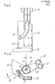
- a blank cylinder 2 includes a cam arm 4 which extends outwardly therefrom terminating in a cam roller 6 which extends into a cam track 8 in cam plate 10 which is mounted on a bracket member 12.
- a blank mold arm 13 is attached to and extends from the cylinder and contains the blank molds 15 as more fully described in U.S. Patent No. 4,339,264.
- Attached to the cam plate 8 is a mounting plate 14 which is attached to the cam plate 10 at its lower end and a neck ring support arm 16 of the machine at its upper end.
- the blank cylinder 2 is mounted on a piston rod 18 which has its lower end secured to the bracket member 12 and its upper end secured to the neck ring support arm 16.
- a piston member 20 is mounted on the piston rod 18.
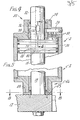
- the upper portion of the blank cylinder 2 includes a cylinder head 22 having a bushing 24 therein which includes a circular chamber 26 which communicates with a passage 28 in the cylinder head containing a plurality of check valves 30 which open into the interior of the cylinder 2 at the top of the piston member 20.
- the check valves 30 are so constructed that they will permit air from chamber 26 to flow into the interior of the cylinder 2 into the top of the piston but will prevent air from passing in the other direction.
- the operating air for the blank cylinder 2 is provided through conduits 32 and 34 within the piston rod 18.
- the air conduit 32 to raise a cylinder with respect to the piston, is shown particularly in Figures 4, 6 and 7.
- the conduit 32 includes a horizontal port 36 which, when the cylinder is in its down position, communicates with the circular chamber 26.
- Extending downwardly from the main port 36 is a double tapered slot 38 as particularly shown in Figures 5 and 7 the end portion of which terminates at approximately the upper portion of the piston member when the cylinder is in its downward position, as will be noted, the slot 38 tapers downward from its greatest depth to its lesser depth and has its sides 40 and 42 tapering inwardly.
- the operation of the mechanism is such that when the cylinder 2 is in its down position, air passes through conduit 32, through port 36, through passageway 28, through check valves 30 and enters the interior of the cylinder at the top of piston member 26 causing the cylinder 2 to raise.
- the bushing 24 passes the port 36 and slot 38, air is directly fed into the interior of the cylinder 2 from the port 36 rather than through passageway 28.
- air at the bottom of the piston member 26 is exhausted through port 44 and conduit 34.
- air is passed through conduit 34 and port 44 to the bottom of the piston member 26 causing the cylinder 2 to move downwardly. Air trapped at the top of the piston member 20 exits through port 36 and conduit 32.
- the bushing 24 begins to cover the port 36 and slot 38 resulting in a reduction of the area from which air can be exhausted. This provides a cushioning for the downward stroke of the cylinder 2.
- a bottom plate 45 is provided against which the lower head 46 of the cylinder 2 abuts.
- the bottom plate 45 is spaced from the bracket member 12 by means of a split shim member 48.
- Two screws 50 extend through the rear of the bottom plate 45 and shim member 48 and are threaded into the bracket member 12 and hold the bottom plate and shim on the bracket member.
- Two locating dowels 52 are provided at the front of the bottom plate 45 and shim 48 extending upwardly from the bracket member 12.
- each forming unit has one split shim 48 provided underneath the bottom plate 45, the thickness of and the number of the shims may be .varied to insure the proper positioning of the blank molds 15.
- cam profile 60 of the cam track 8 in cam plate 10 according to the present invention is basically J-shaped while the cam profile 62 used wILh the prior art as shown in U.S. Patent No. 4,339,264 has a generally S-shaped configuration.
- the cam profile 60 of cam track 8 according to Figure 11 is such that from points A to B the cam track is vertical and there is a straight downward motion of the cylinder 2. From points B to C the cam profile has an increasing radius around an axis to the left of and above the line indicated by B in Figure 11.
- the cam profile 62 includes a straight portion between the lines A and B but includes a radius in one direction between the lines B and C around one general axis and a radius from C to D opposite thereto.
- Such cam has been generally referred to as an S cam.
- cam track profile as shown in Figure 11 is such that as the blank cylinder moves downwardly, its rotational movement has generally a constant acceleration.
- Such a cam profile is can be, but is not limited to a normal trapazoid acceleration curve.
Landscapes
- Engineering & Computer Science (AREA)
- Chemical & Material Sciences (AREA)
- Mechanical Engineering (AREA)
- Manufacturing & Machinery (AREA)
- Materials Engineering (AREA)
- Organic Chemistry (AREA)
- Press Drives And Press Lines (AREA)
- Transmission Devices (AREA)
Applications Claiming Priority (2)
| Application Number | Priority Date | Filing Date | Title |
|---|---|---|---|
| US06/472,365 US4528017A (en) | 1983-03-04 | 1983-03-04 | Blank cylinder apparatus |
| US472365 | 1983-03-04 |
Publications (2)
| Publication Number | Publication Date |
|---|---|
| EP0118298A2 true EP0118298A2 (fr) | 1984-09-12 |
| EP0118298A3 EP0118298A3 (fr) | 1985-07-24 |
Family
ID=23875230
Family Applications (1)
| Application Number | Title | Priority Date | Filing Date |
|---|---|---|---|
| EP84301413A Withdrawn EP0118298A3 (fr) | 1983-03-04 | 1984-03-02 | Appareil de cylindre ébaucheur |
Country Status (2)
| Country | Link |
|---|---|
| US (1) | US4528017A (fr) |
| EP (1) | EP0118298A3 (fr) |
Cited By (2)
| Publication number | Priority date | Publication date | Assignee | Title |
|---|---|---|---|---|
| ITUB20153018A1 (it) * | 2015-08-07 | 2017-02-07 | Olivotto Glass Tech S P A | Testa porta-sbozzo per macchine rotanti atte alla fabbricazione di articoli di vetro cavo. |
| ITUB20153005A1 (it) * | 2015-08-07 | 2017-02-07 | Olivotto Glass Tech S P A | Testa porta-sbozzo con camma sagomata per giostre atte alla fabbricazione di articoli di vetro cavo. |
Families Citing this family (3)
| Publication number | Priority date | Publication date | Assignee | Title |
|---|---|---|---|---|
| GB9319193D0 (en) * | 1993-09-16 | 1993-11-03 | Emhart Glass Mach Invest | Mounting means for a baffle or the like in a glassware manufacturing machine |
| WO2020263068A1 (fr) | 2019-06-26 | 2020-12-30 | Vitro, S.A.B. De C.V. | Mécanisme rotolinéaire pour machines de formage d'articles en verre |
| US20250313085A1 (en) * | 2024-04-05 | 2025-10-09 | Muncie Power Products, Inc. | Adjustable shim |
Family Cites Families (7)
| Publication number | Priority date | Publication date | Assignee | Title |
|---|---|---|---|---|
| US1050287A (en) * | 1910-12-24 | 1913-01-14 | John J Olson | Air-cylinder. |
| US2366777A (en) * | 1941-03-29 | 1945-01-09 | Ralph C Farley | Hydraulic lifting mechanism |
| US2396787A (en) * | 1942-07-14 | 1946-03-19 | Morgan Construction Co | Switching mechanism |
| US2757484A (en) * | 1946-08-05 | 1956-08-07 | Henry C Daubenspeck | Bottle forming machine |
| US3477841A (en) * | 1966-07-19 | 1969-11-11 | Anchor Hocking Corp | Mold support for glassware forming machine |
| US4120683A (en) * | 1977-08-01 | 1978-10-17 | Owens-Illinois, Inc. | Funnel arm operating mechanism |
| US4339264A (en) * | 1980-08-18 | 1982-07-13 | Emhart Industries, Inc. | Glassware forming apparatus |
-
1983
- 1983-03-04 US US06/472,365 patent/US4528017A/en not_active Expired - Lifetime
-
1984
- 1984-03-02 EP EP84301413A patent/EP0118298A3/fr not_active Withdrawn
Cited By (2)
| Publication number | Priority date | Publication date | Assignee | Title |
|---|---|---|---|---|
| ITUB20153018A1 (it) * | 2015-08-07 | 2017-02-07 | Olivotto Glass Tech S P A | Testa porta-sbozzo per macchine rotanti atte alla fabbricazione di articoli di vetro cavo. |
| ITUB20153005A1 (it) * | 2015-08-07 | 2017-02-07 | Olivotto Glass Tech S P A | Testa porta-sbozzo con camma sagomata per giostre atte alla fabbricazione di articoli di vetro cavo. |
Also Published As
| Publication number | Publication date |
|---|---|
| EP0118298A3 (fr) | 1985-07-24 |
| US4528017A (en) | 1985-07-09 |
Similar Documents
| Publication | Publication Date | Title |
|---|---|---|
| US4009018A (en) | Glassware forming machine of the I. S. type with in-line mold motion | |
| WO1984003501A1 (fr) | Appareil ameliore a cylindre d'ebauche | |
| US2702444A (en) | Apparatus for forming glassware | |
| US3585018A (en) | Plunger aligning means | |
| US4120683A (en) | Funnel arm operating mechanism | |
| US4528017A (en) | Blank cylinder apparatus | |
| CA1216154A (fr) | Moule pour machine de mise en forme du verre | |
| US5588981A (en) | Apparatus for forming wide mouth glassware | |
| US4743286A (en) | Moving mechanism for use in a glassware manufacturing machine of the individual section type | |
| JPS635333B2 (fr) | ||
| EP0543495B1 (fr) | Mécanisme à utiliser dans une machine de fabrication d'objets en verre | |
| CA1116405A (fr) | Methode de faconnage de recipients en verre | |
| US4878935A (en) | Supporting mechanism for mould side portions in a glassware forming machine | |
| JP2520885B2 (ja) | ガラス製品成形機のバツフル支持装置 | |
| US4579575A (en) | Blow head supporting and moving mechanism of a glassware forming machine | |
| US3147105A (en) | Apparatus for molding glass | |
| US3271127A (en) | Parison forming apparatus | |
| EP0121346A1 (fr) | Refroidissement de moules de soufflage | |
| US4244726A (en) | Apparatus for manufacturing glass bottles | |
| US3413108A (en) | Glass forming machine having molds with movable bottom sections | |
| US2301139A (en) | Blowing air control for glassware forming machines | |
| US1859230A (en) | Manufacture of hollow glassware | |
| US4764197A (en) | Support for an operative member of a glassware forming machine | |
| US2365929A (en) | Machine for blowing hollow glassware | |
| US1852570A (en) | Glassware forming machine |
Legal Events
| Date | Code | Title | Description |
|---|---|---|---|
| PUAI | Public reference made under article 153(3) epc to a published international application that has entered the european phase |
Free format text: ORIGINAL CODE: 0009012 |
|
| AK | Designated contracting states |
Designated state(s): DE FR GB IT |
|
| PUAL | Search report despatched |
Free format text: ORIGINAL CODE: 0009013 |
|
| AK | Designated contracting states |
Designated state(s): DE FR GB IT |
|
| STAA | Information on the status of an ep patent application or granted ep patent |
Free format text: STATUS: THE APPLICATION IS DEEMED TO BE WITHDRAWN |
|
| 18D | Application deemed to be withdrawn |
Effective date: 19860325 |
|
| RIN1 | Information on inventor provided before grant (corrected) |
Inventor name: BECKWITH, BRUCE ROSCOE Inventor name: ABBOTT, VAUGHAN Inventor name: MUNGOVAN, JOHN PATRICK Inventor name: MILLS, ELDEN HALFORD Inventor name: KINGSBURY, CHARLES MASON |