EP0118322B1 - Von einer Klemme gebildete Mutter - Google Patents
Von einer Klemme gebildete Mutter Download PDFInfo
- Publication number
- EP0118322B1 EP0118322B1 EP84400061A EP84400061A EP0118322B1 EP 0118322 B1 EP0118322 B1 EP 0118322B1 EP 84400061 A EP84400061 A EP 84400061A EP 84400061 A EP84400061 A EP 84400061A EP 0118322 B1 EP0118322 B1 EP 0118322B1
- Authority
- EP
- European Patent Office
- Prior art keywords
- base
- opening
- panel
- fastener
- threaded element
- Prior art date
- Legal status (The legal status is an assumption and is not a legal conclusion. Google has not performed a legal analysis and makes no representation as to the accuracy of the status listed.)
- Expired
Links
Images
Classifications
-
- F—MECHANICAL ENGINEERING; LIGHTING; HEATING; WEAPONS; BLASTING
- F16—ENGINEERING ELEMENTS AND UNITS; GENERAL MEASURES FOR PRODUCING AND MAINTAINING EFFECTIVE FUNCTIONING OF MACHINES OR INSTALLATIONS; THERMAL INSULATION IN GENERAL
- F16B—DEVICES FOR FASTENING OR SECURING CONSTRUCTIONAL ELEMENTS OR MACHINE PARTS TOGETHER, e.g. NAILS, BOLTS, CIRCLIPS, CLAMPS, CLIPS OR WEDGES; JOINTS OR JOINTING
- F16B37/00—Nuts or like thread-engaging members
- F16B37/04—Devices for fastening nuts to surfaces, e.g. sheets, plates
- F16B37/041—Releasable devices
Definitions
- the present invention relates generally to a fastener for fixing a threaded element such as a screw or a bolt to an article such as for example a plate, a panel or the like.
- Fasteners of the above type are already known and which can be inserted by clipping onto the edge of a panel to which another panel can then be fixed after passing a screw through the fastener and the two panels.
- this fastener comprises a base extending by one or two elastic arms folded back to form with the base a clip capable of pinching the edge of a panel, said base comprising an elongated slot as well as two elastic branches which extend from the base on each side of this slot and then approach above the base so that the free edges of the branches define between them an elongated space in alignment with the elongated slot of the base.
- This fastener allows a threaded element, such as for example a screw, to move in an elongated opening of the panel to which the fastener is fixed, and to be received on the one hand in the slot of the base and of on the other hand between the free edges of the elastic branches, thereby allowing the fastening of the fastener due to the contact of the free edges of the elastic branches and the edges of the slot of the base with the threads of the threaded element.
- a threaded element such as for example a screw
- edges of the elastic branches and of the slot are rectilinear, so that the engagement of the threading of the threaded element with these edges does not provide the desired degree of fixation between the threaded element and the fastener.
- a fastener comprising a base extending by an elastic arm folded back to form with the base a clip capable of pinching the edge of a panel.
- the elastic arm allows the passage of a threaded element, while the base has an opening with branches with notched edges which extend on each side of this opening above the base to cooperate with the threaded element .
- the threaded element does not cooperate positively with the opening of the base, and the assembly to be produced may have solidity defects due to the fact that the threaded element is only screwed at the branches with notched edges.
- the present invention aims to provide an improved fastener which overcomes the above drawbacks and allows rigid attachment and without relative displacement of the threaded element in the fastener.
- the subject of the invention is an improved attachment in one piece for fixing an externally threaded element, such as a screw, to a panel or the like by means of an elongated orifice formed through this panel.
- this fastener being of the type comprising a base extending by at least one elastic arm folded over to form with the base a clip capable of pinching the edge of the panel, said base comprising an elongated opening, as well as two elastic branches which extend from the base on each side of this opening and then approach above the base so that the free edges of the branches define between them an elongated space substantially in alignment with the elongated opening of the base, characterized in that the free edges of the branches and the opposite edges of the elongated opening each have a plurality of parts in the form of arcuate notches facing each other in axial alignment with each other so that the el
- the threaded element comes into screw engagement with two arched notches in the elongated opening and then with two corresponding arched notches between the free edges of the
- the elastic arm extending the base is divided into two arms extending respectively to the opposite ends of the elongated opening of the base and in a direction orthogonal to this opening to allow passage between them to the threaded element.
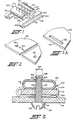
- the fastener 100 comprises a base 104 with an elongated slot 114 comprising two substantially parallel edges which are not identified and which can come into engagement with the threading of a threaded element inserted through the slot 114.
- Two arms 102 are provided. for the fastener 100, which arms extend the base 104, as seen at 106 and extend from a transverse side of the base 104 in the direction of the article up to respective free ends 108 which are spaced from the base 104 to produce an open-ended clip capable of receiving the flange 110 of the panel 112 of FIG. 1A, so as to be able to fix the fastener 100 on the panel 112 by cooperation between the arms 102 and the base 104.
- the arms 102 are spaced apart from one another transversely to the base 104 on the opposite ends of the slot 114 to leave a passage between them allowing the threaded element to be inserted through the elongated opening 130 of the panel 112 and to be received between the edges of the slot 114.
- the opening 130 is substantially parallel to the edge 110 of the panel 112 and that the arms 102 are oriented relative to the slot 114 of the base 104, so that said slot 114 and the opening 130 are aligned when the fastener 100 is clipped onto the edge 110 of the panel 112.
- the fastener 100 comprises a pair of elastic branches 118 and 120 which extend from the base 104 on the opposite sides of the slot 114 to free ends 117 and 119 which are spaced from one another and are located opposite and above the base 104, so as to provide between them an elongated space which is aligned with the slot 114 of the base 104.
- the free ends 117 and 119 include a plurality of spaced and opposite concave curved portions 124 and 126 whose open ends face each other so as to produce a plurality of openings capable of engaging with opposite circumferential portions of the thread of the threaded element.
- each opening of the slot 114 is aligned substantially axially with a corresponding opening between the free ends 117 and 119, so that a threaded element can be moved along the slot 114, then inserted into one of the openings associated with this slot, and finally received in a corresponding opening between the free ends 117 and 119.
- the fastener 100 allows the curved parts of the openings made in the slot 114 and between the free ends 117 and 119, to engage with circumferential parts opposite of the threading of the threaded element so as to make an engagement or a surface contact rather than a point contact which greatly strengthens the fixing of the threaded element to the fastener 100.
- Figure 2 shows a panel 44 which can be attached to the panel 112 of Figure 1A by means of the fastener 100 via one of the spaced holes 46 in the panel 44 or via the two holes 46 whose spacing 132 is less than the length of the orifice 130 in the panel 112 and of the slot 114 in the base 104.
- the attachment of the invention allows a certain degree of misalignment between the orifices in the panels 44 and 112 due to the possibility for the threaded element to move along the slot in the base.
- Figure 3 illustrates the attachment of the panel 44 of Figure 2 to the panel 112 of Figure 1A by means of the fastener 100 and the screw 134 having a thread 138 and a grooved head 136.
- the fastener 100 is clipped onto a edge of the panel 112 thanks to the arm 102 extending from the base 104 as described above.
- the clip 100 is mounted in such a way that the slot 114 (not shown in FIG. 3) of the base 104 is in alignment with the orifice 130 (not shown in FIG. 3) of the panel 112.
- the screw 134 is inserted into the orifice 46 and passes through the passage between the arms 102, so that the thread 138 comes into engagement with the curved parts 127 and 128 of one of the arcuate openings of the slot 114.
- fastener of the invention can be manufactured in several parts, said fastener is preferably made in a single piece stamped from a suitable plastic or metal sheet, while the arms and the elastic branches previously described are folded up as shown in the figures.
Landscapes
- Engineering & Computer Science (AREA)
- General Engineering & Computer Science (AREA)
- Mechanical Engineering (AREA)
- Insertion Pins And Rivets (AREA)
- Dowels (AREA)
- Clamps And Clips (AREA)
- Connection Of Plates (AREA)
- Gripping On Spindles (AREA)
- Joining Of Building Structures In Genera (AREA)
- Adhesives Or Adhesive Processes (AREA)
Claims (2)
Priority Applications (1)
| Application Number | Priority Date | Filing Date | Title |
|---|---|---|---|
| AT84400061T ATE27046T1 (de) | 1983-02-07 | 1984-01-12 | Von einer klemme gebildete mutter. |
Applications Claiming Priority (2)
| Application Number | Priority Date | Filing Date | Title |
|---|---|---|---|
| US46429883A | 1983-02-07 | 1983-02-07 | |
| US464298 | 1983-02-07 |
Publications (2)
| Publication Number | Publication Date |
|---|---|
| EP0118322A1 EP0118322A1 (de) | 1984-09-12 |
| EP0118322B1 true EP0118322B1 (de) | 1987-05-06 |
Family
ID=23843350
Family Applications (1)
| Application Number | Title | Priority Date | Filing Date |
|---|---|---|---|
| EP84400061A Expired EP0118322B1 (de) | 1983-02-07 | 1984-01-12 | Von einer Klemme gebildete Mutter |
Country Status (5)
| Country | Link |
|---|---|
| EP (1) | EP0118322B1 (de) |
| AT (1) | ATE27046T1 (de) |
| CA (1) | CA1229251A (de) |
| DE (2) | DE118322T1 (de) |
| ES (1) | ES277158Y (de) |
Families Citing this family (3)
| Publication number | Priority date | Publication date | Assignee | Title |
|---|---|---|---|---|
| DE19610898A1 (de) * | 1996-03-20 | 1997-09-25 | Hecralmat Fa | Montagescheibe mit Federwirkung und Abstandshaltung |
| DE19733771C1 (de) * | 1997-08-05 | 1999-06-10 | Raymond A & Cie | Lösbare Federmutter für Gewindebolzen |
| CA2846708C (en) | 2013-03-15 | 2017-12-12 | Pemko Manufacturing Company, Inc. | Vision lite and screw boss channel |
Family Cites Families (5)
| Publication number | Priority date | Publication date | Assignee | Title |
|---|---|---|---|---|
| US2797720A (en) * | 1953-12-14 | 1957-07-02 | Gen Motors Corp | Sheet metal nut with screw slot having frangible serrations |
| CH480549A (de) * | 1967-10-25 | 1969-10-31 | Underberg Emil Ewald Josef | Vorrichtung zum Befestigen von Teilen auf einer Unterlage mittels Schrauben |
| DE7007594U (de) * | 1970-03-03 | 1970-09-17 | Wieland Werke Ag | Schraubverbindung, insbesondere zur verwendung bei metallenen fenster- oder tuerrahmen. |
| DE2617940A1 (de) * | 1976-04-24 | 1977-11-03 | Daimler Benz Ag | Kaefigmutter |
| GB2102905B (en) * | 1981-07-27 | 1985-01-03 | Canning Brett Limited | Improvements in captive nuts |
-
1983
- 1983-12-08 CA CA000442872A patent/CA1229251A/en not_active Expired
-
1984
- 1984-01-12 DE DE198484400061T patent/DE118322T1/de active Pending
- 1984-01-12 DE DE8484400061T patent/DE3463556D1/de not_active Expired
- 1984-01-12 AT AT84400061T patent/ATE27046T1/de not_active IP Right Cessation
- 1984-01-12 EP EP84400061A patent/EP0118322B1/de not_active Expired
- 1984-01-27 ES ES1984277158U patent/ES277158Y/es not_active Expired
Also Published As
| Publication number | Publication date |
|---|---|
| DE118322T1 (de) | 1986-02-13 |
| ATE27046T1 (de) | 1987-05-15 |
| CA1229251A (en) | 1987-11-17 |
| EP0118322A1 (de) | 1984-09-12 |
| ES277158Y (es) | 1985-05-16 |
| DE3463556D1 (en) | 1987-06-11 |
| ES277158U (es) | 1984-11-16 |
Similar Documents
| Publication | Publication Date | Title |
|---|---|---|
| EP0199614B1 (de) | Klammerähnliches Befestigungsmittel | |
| FR2652131A1 (fr) | Piece plate ayant la faculte d'etirement elastique dans la direction longitudinale, son procede de fabrication et son application a un collier de serrage. | |
| EP0837256B1 (de) | Klammermutter für Profile | |
| FR2623835A1 (fr) | Suspente pour element d'ossature, en particulier pour plafond a ossature metallique | |
| EP0669470B1 (de) | Universelle Halterung, insbesondere für die Befestigung einer elektrischen Ausrüstung | |
| EP0407282B1 (de) | Klammerartige Mutter zum Montieren auf den Rand einer Platte oder dergleichen | |
| FR2979400A1 (fr) | Structure de fixation utilisant des pinces | |
| EP1230839A1 (de) | Anlage zum Aufbinden, insbesondere der Reben | |
| FR2689837A1 (fr) | Dispositif d'essuie-glace incorporant un déflecteur. | |
| EP0683327B1 (de) | Befestigungselement für Kabel, Rohre oder dergleichen | |
| EP0118322A1 (de) | Von einer Klemme gebildete Mutter | |
| FR2766905A1 (fr) | Profile a rainure(s) pour la mise en place d'au moins un accessoire | |
| FR2518192A1 (fr) | Dispositif d'assemblage de deux pieces, telles que deux profiles realises par exemple en alliage leger | |
| FR2719347A1 (fr) | Ecrou en forme de pince insérable sur le bord d'un panneau ou analogue. | |
| FR2659104A1 (fr) | Attache a ecrou incorpore en particulier pour la fixation provisoire d'un grillage sur des poteaux ou analogues. | |
| EP0348284B1 (de) | Schnürverschluss für Schuhe | |
| FR2649762A1 (fr) | Attache | |
| FR2627553A1 (fr) | Attache | |
| FR2655932A1 (fr) | Dispositif deflecteur pour balai d'essuie-glace. | |
| FR2583469A1 (fr) | Ecrou encage | |
| FR2796427A1 (fr) | Dispositif de premontage d'un ecrou pour ensemble de fixation du type vis-ecrou | |
| FR2653183A1 (fr) | Attache pour la fixation d'un element par exemple tubulaire sur une paroi quelconque. | |
| EP0077695B1 (de) | Befestigungselement mit Mutternhalterung | |
| FR2687439A1 (fr) | Ecrou a fut taraude et element tel que panneau muni de cet ecrou. | |
| EP0115239A1 (de) | Profilschiene und Mutter zum Befestigen von Geräten |
Legal Events
| Date | Code | Title | Description |
|---|---|---|---|
| PUAI | Public reference made under article 153(3) epc to a published international application that has entered the european phase |
Free format text: ORIGINAL CODE: 0009012 |
|
| AK | Designated contracting states |
Designated state(s): AT BE CH DE FR GB IT LI LU NL SE |
|
| 17P | Request for examination filed |
Effective date: 19841010 |
|
| ITCL | It: translation for ep claims filed |
Representative=s name: DE DOMINICIS & PARTNERS |
|
| TCAT | At: translation of patent claims filed | ||
| TCNL | Nl: translation of patent claims filed | ||
| DET | De: translation of patent claims | ||
| GRAA | (expected) grant |
Free format text: ORIGINAL CODE: 0009210 |
|
| AK | Designated contracting states |
Kind code of ref document: B1 Designated state(s): AT BE CH DE FR GB IT LI LU NL SE |
|
| PG25 | Lapsed in a contracting state [announced via postgrant information from national office to epo] |
Ref country code: NL Effective date: 19870506 Ref country code: AT Effective date: 19870506 |
|
| REF | Corresponds to: |
Ref document number: 27046 Country of ref document: AT Date of ref document: 19870515 Kind code of ref document: T |
|
| REF | Corresponds to: |
Ref document number: 3463556 Country of ref document: DE Date of ref document: 19870611 |
|
| ITF | It: translation for a ep patent filed | ||
| NLV1 | Nl: lapsed or annulled due to failure to fulfill the requirements of art. 29p and 29m of the patents act | ||
| PG25 | Lapsed in a contracting state [announced via postgrant information from national office to epo] |
Ref country code: LU Free format text: LAPSE BECAUSE OF NON-PAYMENT OF DUE FEES Effective date: 19880131 Ref country code: LI Effective date: 19880131 Ref country code: CH Effective date: 19880131 |
|
| PLBE | No opposition filed within time limit |
Free format text: ORIGINAL CODE: 0009261 |
|
| STAA | Information on the status of an ep patent application or granted ep patent |
Free format text: STATUS: NO OPPOSITION FILED WITHIN TIME LIMIT |
|
| 26N | No opposition filed | ||
| BERE | Be: lapsed |
Owner name: EATON COR. Effective date: 19880131 |
|
| REG | Reference to a national code |
Ref country code: CH Ref legal event code: PL |
|
| PG25 | Lapsed in a contracting state [announced via postgrant information from national office to epo] |
Ref country code: BE Effective date: 19890131 |
|
| ITTA | It: last paid annual fee | ||
| PGFP | Annual fee paid to national office [announced via postgrant information from national office to epo] |
Ref country code: FR Payment date: 19911122 Year of fee payment: 9 |
|
| PGFP | Annual fee paid to national office [announced via postgrant information from national office to epo] |
Ref country code: GB Payment date: 19920103 Year of fee payment: 9 |
|
| PGFP | Annual fee paid to national office [announced via postgrant information from national office to epo] |
Ref country code: SE Payment date: 19920122 Year of fee payment: 9 |
|
| PGFP | Annual fee paid to national office [announced via postgrant information from national office to epo] |
Ref country code: DE Payment date: 19920131 Year of fee payment: 9 |
|
| PG25 | Lapsed in a contracting state [announced via postgrant information from national office to epo] |
Ref country code: GB Effective date: 19930112 |
|
| PG25 | Lapsed in a contracting state [announced via postgrant information from national office to epo] |
Ref country code: SE Effective date: 19930113 |
|
| GBPC | Gb: european patent ceased through non-payment of renewal fee |
Effective date: 19930112 |
|
| PG25 | Lapsed in a contracting state [announced via postgrant information from national office to epo] |
Ref country code: FR Effective date: 19930930 |
|
| PG25 | Lapsed in a contracting state [announced via postgrant information from national office to epo] |
Ref country code: DE Effective date: 19931001 |
|
| REG | Reference to a national code |
Ref country code: FR Ref legal event code: ST |
|
| EUG | Se: european patent has lapsed |
Ref document number: 84400061.2 Effective date: 19930810 |