EP0118330B1 - Schneckenverdichter für Schlamm - Google Patents
Schneckenverdichter für Schlamm Download PDFInfo
- Publication number
- EP0118330B1 EP0118330B1 EP84400180A EP84400180A EP0118330B1 EP 0118330 B1 EP0118330 B1 EP 0118330B1 EP 84400180 A EP84400180 A EP 84400180A EP 84400180 A EP84400180 A EP 84400180A EP 0118330 B1 EP0118330 B1 EP 0118330B1
- Authority
- EP
- European Patent Office
- Prior art keywords
- suspension
- threads
- friction
- coefficient
- screw
- Prior art date
- Legal status (The legal status is an assumption and is not a legal conclusion. Google has not performed a legal analysis and makes no representation as to the accuracy of the status listed.)
- Expired
Links
- 230000008719 thickening Effects 0.000 title claims abstract description 25
- 239000010802 sludge Substances 0.000 title claims description 10
- 239000000725 suspension Substances 0.000 claims abstract description 51
- 239000007788 liquid Substances 0.000 claims abstract description 34
- 239000007787 solid Substances 0.000 claims abstract description 7
- 239000002245 particle Substances 0.000 claims description 5
- 230000007423 decrease Effects 0.000 claims description 3
- 230000000694 effects Effects 0.000 abstract description 7
- 238000000576 coating method Methods 0.000 description 14
- 239000011248 coating agent Substances 0.000 description 12
- 238000000034 method Methods 0.000 description 4
- 230000003247 decreasing effect Effects 0.000 description 3
- 239000000463 material Substances 0.000 description 3
- 238000012546 transfer Methods 0.000 description 3
- 238000011144 upstream manufacturing Methods 0.000 description 3
- 230000015572 biosynthetic process Effects 0.000 description 2
- 238000000926 separation method Methods 0.000 description 2
- 239000002562 thickening agent Substances 0.000 description 2
- 208000034699 Vitreous floaters Diseases 0.000 description 1
- 238000013459 approach Methods 0.000 description 1
- 238000005352 clarification Methods 0.000 description 1
- 239000004927 clay Substances 0.000 description 1
- 230000006835 compression Effects 0.000 description 1
- 238000007906 compression Methods 0.000 description 1
- 239000012141 concentrate Substances 0.000 description 1
- 239000000470 constituent Substances 0.000 description 1
- 229920001971 elastomer Polymers 0.000 description 1
- 238000000605 extraction Methods 0.000 description 1
- 238000005189 flocculation Methods 0.000 description 1
- 230000016615 flocculation Effects 0.000 description 1
- 239000011521 glass Substances 0.000 description 1
- 239000012535 impurity Substances 0.000 description 1
- 229910052500 inorganic mineral Inorganic materials 0.000 description 1
- 239000011707 mineral Substances 0.000 description 1
- 238000012986 modification Methods 0.000 description 1
- 230000004048 modification Effects 0.000 description 1
- 239000005416 organic matter Substances 0.000 description 1
- 238000012856 packing Methods 0.000 description 1
- 239000003973 paint Substances 0.000 description 1
- 238000005498 polishing Methods 0.000 description 1
- 229920001084 poly(chloroprene) Polymers 0.000 description 1
- 230000001737 promoting effect Effects 0.000 description 1
- 238000004064 recycling Methods 0.000 description 1
- 239000000126 substance Substances 0.000 description 1
- 238000012360 testing method Methods 0.000 description 1
- 239000002966 varnish Substances 0.000 description 1
Images
Classifications
-
- B—PERFORMING OPERATIONS; TRANSPORTING
- B30—PRESSES
- B30B—PRESSES IN GENERAL
- B30B9/00—Presses specially adapted for particular purposes
- B30B9/02—Presses specially adapted for particular purposes for squeezing-out liquid from liquid-containing material, e.g. juice from fruits, oil from oil-containing material
- B30B9/12—Presses specially adapted for particular purposes for squeezing-out liquid from liquid-containing material, e.g. juice from fruits, oil from oil-containing material using pressing worms or screws co-operating with a permeable casing
- B30B9/121—Screw constructions
-
- B—PERFORMING OPERATIONS; TRANSPORTING
- B01—PHYSICAL OR CHEMICAL PROCESSES OR APPARATUS IN GENERAL
- B01D—SEPARATION
- B01D21/00—Separation of suspended solid particles from liquids by sedimentation
- B01D21/24—Feed or discharge mechanisms for settling tanks
- B01D21/245—Discharge mechanisms for the sediments
-
- B—PERFORMING OPERATIONS; TRANSPORTING
- B30—PRESSES
- B30B—PRESSES IN GENERAL
- B30B9/00—Presses specially adapted for particular purposes
- B30B9/02—Presses specially adapted for particular purposes for squeezing-out liquid from liquid-containing material, e.g. juice from fruits, oil from oil-containing material
- B30B9/12—Presses specially adapted for particular purposes for squeezing-out liquid from liquid-containing material, e.g. juice from fruits, oil from oil-containing material using pressing worms or screws co-operating with a permeable casing
- B30B9/18—Presses specially adapted for particular purposes for squeezing-out liquid from liquid-containing material, e.g. juice from fruits, oil from oil-containing material using pressing worms or screws co-operating with a permeable casing with means for adjusting the outlet for the solid
Definitions
- the present invention relates to an improved apparatus for thickening a suspension of solid particles in a liquid, such as a possibly flocculated mud, which comprises a rotary worm extending longitudinally in a cylindrical enclosure provided with at least a suspension inlet to be thickened, a thickened suspension outlet situated in the vicinity of the anterior end of the screw and at least one outlet for thickening liquid.
- a rotary worm extending longitudinally in a cylindrical enclosure provided with at least a suspension inlet to be thickened, a thickened suspension outlet situated in the vicinity of the anterior end of the screw and at least one outlet for thickening liquid.
- the screw by its rotational movement, causes the suspension to transfer from the rear end to the front end of the cylinder, that is to say to the thickened suspension outlet at the level of which it forms, possibly in cooperation with appropriate means, a plug which prevents the ejection by this outlet of the thickening liquid and more or less slows down the outlet of the thickened suspension which therefore undergoes more compacting or less important.
- the suspension is pressed against the thrust face of the threads of the screw, which results in separation of the liquid and therefore a gradual thickening of the suspension, the separated thickening liquid being discharged towards the outlet.
- the pressure exerted by the screw on the suspension remains substantially constant throughout the thickening process, that is to say throughout the progression of the suspension from the end posterior to the 'anterior end of the cylindrical enclosure. It will be understood under these conditions that if the concentration of sludge is relatively easy in the rear part of the cylindrical enclosure where the viscosity of said sludge is low, this concentration is less and less easy to obtain as the viscosity of the sludge increases, that is to say as the latter progresses within the enclosure. This necessarily results in a limitation of the degree of thickening of the sludge leaving the device.
- DE-C-266 077 describes an endless screw apparatus for the transport of sludge apparatus in which the faces of the endless screw are provided with a rough coating intended to promote the separation between the clay constituents and the impurities contained in said sludge.
- DE-C-548 411 describes a worm screw press for extracting the oil contained in an oil-impregnated material, the threads of the worm screw being provided with grooves exerting a friction effect and grinding on said oil-impregnated material, favoring the extraction of the oil.
- the present invention provides a device of the type defined in the first paragraph of this description and which is characterized in that all or part of the threads of the screw have, on their thrust face , a coefficient of friction higher than that of the rear face of the threads.
- the coefficient of friction of the thrust face of the threads can be variable and increasing from the posterior end to the anterior end of the screw. Indeed, in the posterior zone of the enclosure where the suspension is very rich in liquid, the latter is fairly easily separated from the suspension due to the low viscosity of the latter. The coefficient of friction can therefore be lower in this posterior region than the coefficient of friction in the anterior region of the screw where the suspension has a high viscosity which, by nature, is difficult to concentrate.
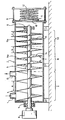
- the suspension to be thickened is brought by a tube 1 into the upstream part of a horizontal cylindrical enclosure 2 in which a worm screw 3 extends longitudinally, the tubing 1 opening into the enclosure 2 via the cylindrical wall 4 of the latter.
- the screw 3 is mounted for rotation in the enclosure 2 by means of two bearings 5, 6 with a minimum clearance between the top of the threads 7 of the screw and the enclosure 2.
- this screw 3 is brought into rotation by a motor 8 comprising appropriate means making it possible to adjust the speed of rotation of the screw 3 to the value, easily determinable by tests, making it possible to obtain the desired thickening under the best conditions.
- the screw 3 is with variable pitch (a> b> c), this pitch decreasing in successive stages I, II, III from the upstream end to the downstream end of the enclosure, considering the direction of progression of the suspension . It should also be noted that the last thread of the anterior end of the screw 3 is located at such a distance from the downstream side face 9 of the enclosure 2, so that it can form between this last thread and the face 9 a thickened suspension plug.
- the side face 9 is for its part provided with an opening 10 for the evacuation of the thickened suspension, which cooperates with a shutter 11 pressed by a spring 12 or any other equivalent means on the edges of the opening 10.
- the cylindrical wall 4 carries, in addition to the pipe 1, a pipe 13 for the outlet of thickening liquid, disposed downstream of said pipe 1.
- the suspension to be thickened entering the enclosure through the tubing 1 is transferred by the worm screw 3 towards the downstream end of the enclosure, that is to say towards the opening 10. During this transfer, the suspension is pressed against the thrust face of the threads of the screw, this face thus exerting pressure on said suspension, this pressure having the effect of expressing the liquid in the suspension.
- each thread 7 On the thrust face of each thread 7, it turns. therefore forms a suspension deposit less and less rich in liquid as one moves away from the tube 1, the liquid expelled from the suspension (thickening liquid) coming to take place between this deposit and the rear face of the next thread before moving away towards the pipe 13 which, to ensure good evacuation of said expelled liquid, is preferably disposed between two successive threads of the screw 3 and near the rear face of the downstream thread.
- This difficulty is overcome by the implementation of an endless screw 3 of which all or part of the threads have on their thrust face, a high coefficient of friction, as is explained below.
- the presence of said plug prevents the evacuation of the thickening liquid through the opening 10; therefore, as it separates from the suspension, this thickening liquid flows towards the tube 13. It should be noted, however, that the packing effect mentioned above can be obtained, although '' to a lesser degree, in the absence of the shutter 11 and the spring 12. In fact, there is also in this case formation of a thickened suspension plug between the last anterior thread of the screw and the opening 10, this plug slowing the outlet of the thickened suspension through said opening 10 and ensuring thereby the desired settlement.
- an endless screw in which all or part of the threads have, at least on their thrust face, a high coefficient of friction. It is however even more advantageous to use a screw whose threads have a thrust face having a coefficient of friction greater than that of the rear face of these same threads.
- the coating 15 advantageously has a coefficient of friction greater than that of the coating 14.
- the coatings in question can easily be chosen according to the nature of the solid particles and the desired coefficient of friction and they can by example be constituted by a layer of neoprene paint or by a thin layer of rubber.
- a physical treatment such as sanding to modify the surface condition of their thrust face, this treatment being good understood to give the thrust face of the threads of the bearing III a coefficient of friction greater than that given to the thrust face of the threads of the bearing II.
- a coating 14a and a coating 15a are deposited on the rear face corresponding to the bearings II and III respectively, making it possible to lower the coefficient of friction on this rear face, the coating 15a advantageously having a coefficient of friction lower than that of the coating 14a.
- the coatings in question can be easily determined as a function of the desired coefficient of friction and will generally consist of any material capable of forming a coating with a smooth surface such as glass or certain varnishes for example.
- another way of lowering the coefficient of friction of the rear face of the threads would be to modify the surface condition of this face (polishing for example).
- the tube 13 could be replaced by an opening in the cylindrical wall 4 and extending over a more or less long length of the enclosure 2; the cylindrical wall 4 could be formed over at least part of its length, by a filter grid through which the thickening liquid is discharged, this grid playing the same role as the tubing 13 and can therefore be substituted for the latter ;
- the pitch of the screw 3 instead of being decreasing in successive stages, could decrease continuously from the upstream end to the downstream end of the enclosure 2;
- the threads corresponding to the bearing I could also include, on their pushing face, a coating of a nature to increase the coefficient of friction and, on their rear face, a coating of a nature to lower the coefficient of friction, so that on said thrust face the coefficient of friction increases from the rear end to the front end of the screw and on said rear face the coefficient of friction decreases from the rear end to the front end of the screw;
- the friction coefficients in successive steps they could be varied continuously.
Landscapes
- Engineering & Computer Science (AREA)
- Mechanical Engineering (AREA)
- Chemical & Material Sciences (AREA)
- Chemical Kinetics & Catalysis (AREA)
- Centrifugal Separators (AREA)
- Treatment Of Sludge (AREA)
- Addition Polymer Or Copolymer, Post-Treatments, Or Chemical Modifications (AREA)
- Paper (AREA)
Claims (5)
Priority Applications (1)
| Application Number | Priority Date | Filing Date | Title |
|---|---|---|---|
| AT84400180T ATE26435T1 (de) | 1983-02-02 | 1984-01-27 | Schneckenverdichter fuer schlamm. |
Applications Claiming Priority (2)
| Application Number | Priority Date | Filing Date | Title |
|---|---|---|---|
| FR8301646 | 1983-02-02 | ||
| FR8301646A FR2540094B1 (fr) | 1983-02-02 | 1983-02-02 | Perfectionnement aux epaississeurs de boues a vis |
Publications (2)
| Publication Number | Publication Date |
|---|---|
| EP0118330A1 EP0118330A1 (de) | 1984-09-12 |
| EP0118330B1 true EP0118330B1 (de) | 1987-04-08 |
Family
ID=9285546
Family Applications (1)
| Application Number | Title | Priority Date | Filing Date |
|---|---|---|---|
| EP84400180A Expired EP0118330B1 (de) | 1983-02-02 | 1984-01-27 | Schneckenverdichter für Schlamm |
Country Status (8)
| Country | Link |
|---|---|
| US (1) | US4528098A (de) |
| EP (1) | EP0118330B1 (de) |
| AT (1) | ATE26435T1 (de) |
| CA (1) | CA1204734A (de) |
| DE (1) | DE3463031D1 (de) |
| FR (1) | FR2540094B1 (de) |
| IN (1) | IN161948B (de) |
| ZA (1) | ZA84747B (de) |
Families Citing this family (16)
| Publication number | Priority date | Publication date | Assignee | Title |
|---|---|---|---|---|
| US4720047A (en) * | 1986-12-12 | 1988-01-19 | Knight Manufacturing Corporation | Auger for conveying materials such as manure |
| CA1309954C (en) * | 1987-07-29 | 1992-11-10 | Yasuo Yamada | Deaerator for particulates |
| US5435494A (en) * | 1992-02-06 | 1995-07-25 | Knight Manufacturing Corp. | Spreader apparatus for spreading manure |
| JP3049167B2 (ja) * | 1992-02-06 | 2000-06-05 | ナイト マニファクチャリング コーポレイション | 施肥用の散布装置 |
| US5385403A (en) * | 1992-02-06 | 1995-01-31 | Knight Manufacturing Corp. | Mixing apparatus for mixing materials |
| US5494351A (en) * | 1992-10-14 | 1996-02-27 | Vapo Oy | Device and method for mixing peat and sludge |
| US5761888A (en) * | 1996-09-19 | 1998-06-09 | Carbonic Industries Corporation | Method and apparatus for conveying dry ice |
| SE507498C2 (sv) * | 1996-10-07 | 1998-06-15 | Spirac Engineering Ab | Separationsanordning försedd med transportspiral och silorgan |
| US6170580B1 (en) * | 1997-07-17 | 2001-01-09 | Jeffery Reddoch | Method and apparatus for collecting, defluidizing and disposing of oil and gas well drill cuttings |
| JPH11216313A (ja) * | 1998-02-03 | 1999-08-10 | Ishikawajima Harima Heavy Ind Co Ltd | 脱水濃縮装置 |
| US6241902B1 (en) | 1999-11-22 | 2001-06-05 | Wawcon, Inc. | Methods and apparatus for de-watering sludge |
| US7976259B2 (en) * | 2007-07-16 | 2011-07-12 | Joe David Craig | System for feeding biomass into a pressurized vessel |
| US20090022570A1 (en) * | 2007-07-16 | 2009-01-22 | Joe David Craig | System, method and apparatus for feeding biomass into a pressurized vessel |
| IT1393420B1 (it) * | 2009-03-19 | 2012-04-20 | Ceccarelli | Apparato per la compattazione e la disidratazione di rifiuti organici |
| US20160235110A1 (en) * | 2015-02-17 | 2016-08-18 | Frito-Lay North America, Inc. | Method and apparatus for controlling the flow of product over a product attrition bed |
| AT518550B1 (de) * | 2016-07-29 | 2017-11-15 | Andritz Ag Maschf | Schneckenpresse |
Family Cites Families (11)
| Publication number | Priority date | Publication date | Assignee | Title |
|---|---|---|---|---|
| DE548411C (de) * | 1932-04-15 | Fried Krupp Grusonwerk Akt Ges | Schneckenpresse fuer feuchtes Gut | |
| DE266077C (de) * | ||||
| FR1015977A (fr) * | 1950-04-05 | 1952-10-29 | Perfectionnements aux appareils de décantation | |
| US2701518A (en) * | 1950-10-23 | 1955-02-08 | Manuel C Mcdonald | Worm |
| DE1243914B (de) * | 1961-06-05 | 1967-07-06 | Bedrijven Van Het Nl I Voor Zu | Vorrichtung zum Abtrennen der Molke aus einem Bruch-Molke-Gemisch |
| FR1532464A (fr) * | 1967-05-26 | 1968-07-12 | Dispositif pour le traitement des matières fibreuses en vue de l'extraction des substances liquides qu'elles contiennent | |
| US3624729A (en) * | 1968-01-29 | 1971-11-30 | Maurice W Hoover | Continuous juice extractor |
| US3550526A (en) * | 1968-01-29 | 1970-12-29 | Maurice W Hoover | Continuous juice extractor |
| US3585924A (en) * | 1969-03-10 | 1971-06-22 | William J Nolan | Apparatus for the removal of liquids from fibrous materials |
| JPS5551000A (en) * | 1978-10-06 | 1980-04-14 | Sanshin Seisakusho:Kk | Screw press unit |
| US4380496A (en) * | 1979-03-22 | 1983-04-19 | Uop Inc. | Mechanical dewatering process utilizing a nonuniform screw conveyor |
-
1983
- 1983-02-02 FR FR8301646A patent/FR2540094B1/fr not_active Expired
-
1984
- 1984-01-26 US US06/573,880 patent/US4528098A/en not_active Expired - Fee Related
- 1984-01-27 DE DE8484400180T patent/DE3463031D1/de not_active Expired
- 1984-01-27 AT AT84400180T patent/ATE26435T1/de not_active IP Right Cessation
- 1984-01-27 EP EP84400180A patent/EP0118330B1/de not_active Expired
- 1984-01-30 IN IN63/CAL/84A patent/IN161948B/en unknown
- 1984-01-31 CA CA000446379A patent/CA1204734A/en not_active Expired
- 1984-02-01 ZA ZA84747A patent/ZA84747B/xx unknown
Also Published As
| Publication number | Publication date |
|---|---|
| FR2540094A1 (fr) | 1984-08-03 |
| IN161948B (de) | 1988-03-05 |
| US4528098A (en) | 1985-07-09 |
| EP0118330A1 (de) | 1984-09-12 |
| CA1204734A (en) | 1986-05-20 |
| ATE26435T1 (de) | 1987-04-15 |
| DE3463031D1 (en) | 1987-05-14 |
| FR2540094B1 (fr) | 1986-01-03 |
| ZA84747B (en) | 1984-09-26 |
Similar Documents
| Publication | Publication Date | Title |
|---|---|---|
| EP0118330B1 (de) | Schneckenverdichter für Schlamm | |
| CA1070866A (fr) | Procede pour le compactage et l'essorage des boues fluides chargees de matieres fibreuses | |
| EP0328555B1 (de) | Trennungs-verfahren und -vorrichtung einer dispergierten phase | |
| WO2002032539A1 (fr) | Installation de mesure de la concentration en materiau granulaire dense d"un ecoulement et systeme pour le traitement de l"eau incluant une telle installation | |
| FR2546419A1 (fr) | Appareillage pour deshydrater de la boue dans la zone de centrifugation d'une centrifugeuse a enveloppe pleine | |
| EP0243243B1 (de) | Verfahren und Vorrichtung zur Abscheidung von Komponenten aus einer Suspension | |
| FR2767521A1 (fr) | Procede et installation pour le traitement des eaux integrant un decanteur et un filtre multi-couches fonctionnant a grandes vitesses | |
| FR2954174A1 (fr) | Procede de potabilisation et/ou d'epuration d'eau comprenant l'elimination d'un compose cible et une filtration au sein d'un tambour filtrant | |
| EP0524039B1 (de) | Verfahren und Vorrichtung zur Wasserbehandlung | |
| FR2941225A1 (fr) | Dispositif d'enrobage avec un materiau polymere floculant a l'etat liquide de grains de ballast utilises pour le traitement de l'eau par floculation lestee, et installation correspondante. | |
| EP1027290B1 (de) | Verfahren zur physico-chemischen behandlung von wasser und einrichtung dafür | |
| FR2502512A1 (fr) | Appareil d'extraction de corps lourds etrangers de matieres moins denses telles que des recoltes, transportees dans un liquide | |
| FR2540485A1 (fr) | Epaississeur de boue comportant des moyens de decantation et des moyens d'essorage | |
| JP3874314B2 (ja) | 油中のスラッジ除去方法 | |
| WO2008093017A2 (fr) | Dispositif et procede de filtration d'eau, en particulier d'eaux de surface | |
| FR2591128A1 (fr) | Procede et dispositif pour enrichir la phase decantee dans les traitements de separation par flottation des matieres huileuses ou similaires contenues dans un liquide pollue. | |
| EP0808216B1 (de) | Verfahren und apparat zur elektrostatischen reinigung von organischen flüssigkeiten | |
| BE502917A (de) | ||
| FR2559777A1 (fr) | Procede de production d'un melange de charbon et d'eau, destine notamment a un haut fourneau, une chaudiere ou autres | |
| WO2020083782A1 (fr) | Procede de traitement par adsorption sur charbon actif sans etape de floculation et sans injection de coagulant | |
| CH364740A (fr) | Procédé de classement densimétrique de minerais, hydrotamis pour la mise en oeuvre de ce procédé et application de ce procédé | |
| FR2642326A1 (fr) | Dispositif d'epuration/filtration d'un melange fluide d'un composant a separer d'impuretes, notamment pour installation de plumage a la cire | |
| CH689348A5 (fr) | Installation de filtration de liquides avec des particules en suspension. | |
| CA2108900A1 (fr) | Procede et dispositif de purification d'un liquide electriquement non conducteur | |
| FR2487691A1 (fr) | Procede de separation de la phase solide d'une boue de forage |
Legal Events
| Date | Code | Title | Description |
|---|---|---|---|
| PUAI | Public reference made under article 153(3) epc to a published international application that has entered the european phase |
Free format text: ORIGINAL CODE: 0009012 |
|
| AK | Designated contracting states |
Designated state(s): AT BE CH DE GB IT LI LU NL SE |
|
| 17P | Request for examination filed |
Effective date: 19850123 |
|
| GRAA | (expected) grant |
Free format text: ORIGINAL CODE: 0009210 |
|
| AK | Designated contracting states |
Kind code of ref document: B1 Designated state(s): AT BE CH DE GB IT LI LU NL SE |
|
| PG25 | Lapsed in a contracting state [announced via postgrant information from national office to epo] |
Ref country code: AT Effective date: 19870408 |
|
| RAP1 | Party data changed (applicant data changed or rights of an application transferred) |
Owner name: SOCIETE ANONYME D'ETUDES DE RECHERCHES ET DE PRODU |
|
| REF | Corresponds to: |
Ref document number: 26435 Country of ref document: AT Date of ref document: 19870415 Kind code of ref document: T |
|
| ITF | It: translation for a ep patent filed | ||
| PG25 | Lapsed in a contracting state [announced via postgrant information from national office to epo] |
Ref country code: SE Effective date: 19870430 |
|
| REF | Corresponds to: |
Ref document number: 3463031 Country of ref document: DE Date of ref document: 19870514 |
|
| PG25 | Lapsed in a contracting state [announced via postgrant information from national office to epo] |
Ref country code: LU Free format text: LAPSE BECAUSE OF NON-PAYMENT OF DUE FEES Effective date: 19880131 |
|
| PLBE | No opposition filed within time limit |
Free format text: ORIGINAL CODE: 0009261 |
|
| STAA | Information on the status of an ep patent application or granted ep patent |
Free format text: STATUS: NO OPPOSITION FILED WITHIN TIME LIMIT |
|
| 26N | No opposition filed | ||
| PGFP | Annual fee paid to national office [announced via postgrant information from national office to epo] |
Ref country code: NL Payment date: 19890131 Year of fee payment: 8 |
|
| PGFP | Annual fee paid to national office [announced via postgrant information from national office to epo] |
Ref country code: LU Payment date: 19900119 Year of fee payment: 7 |
|
| PGFP | Annual fee paid to national office [announced via postgrant information from national office to epo] |
Ref country code: DE Payment date: 19900122 Year of fee payment: 7 |
|
| ITTA | It: last paid annual fee | ||
| PGFP | Annual fee paid to national office [announced via postgrant information from national office to epo] |
Ref country code: GB Payment date: 19900131 Year of fee payment: 7 |
|
| PGFP | Annual fee paid to national office [announced via postgrant information from national office to epo] |
Ref country code: BE Payment date: 19900213 Year of fee payment: 7 |
|
| PGFP | Annual fee paid to national office [announced via postgrant information from national office to epo] |
Ref country code: CH Payment date: 19900330 Year of fee payment: 7 |
|
| PG25 | Lapsed in a contracting state [announced via postgrant information from national office to epo] |
Ref country code: GB Effective date: 19910127 |
|
| PG25 | Lapsed in a contracting state [announced via postgrant information from national office to epo] |
Ref country code: LI Effective date: 19910131 Ref country code: CH Effective date: 19910131 Ref country code: BE Effective date: 19910131 |
|
| PG25 | Lapsed in a contracting state [announced via postgrant information from national office to epo] |
Ref country code: NL Effective date: 19910801 |
|
| NLV4 | Nl: lapsed or anulled due to non-payment of the annual fee | ||
| GBPC | Gb: european patent ceased through non-payment of renewal fee | ||
| REG | Reference to a national code |
Ref country code: CH Ref legal event code: PL |
|
| PG25 | Lapsed in a contracting state [announced via postgrant information from national office to epo] |
Ref country code: DE Effective date: 19911001 |