EP0118344A1 - Digitale Antriebssteuerung - Google Patents
Digitale Antriebssteuerung Download PDFInfo
- Publication number
- EP0118344A1 EP0118344A1 EP84400271A EP84400271A EP0118344A1 EP 0118344 A1 EP0118344 A1 EP 0118344A1 EP 84400271 A EP84400271 A EP 84400271A EP 84400271 A EP84400271 A EP 84400271A EP 0118344 A1 EP0118344 A1 EP 0118344A1
- Authority
- EP
- European Patent Office
- Prior art keywords
- piston
- valves
- valve
- source
- disc
- Prior art date
- Legal status (The legal status is an assumption and is not a legal conclusion. Google has not performed a legal analysis and makes no representation as to the accuracy of the status listed.)
- Withdrawn
Links
- 239000012530 fluid Substances 0.000 claims abstract description 12
- 238000006073 displacement reaction Methods 0.000 description 12
- 230000009471 action Effects 0.000 description 2
- 230000000295 complement effect Effects 0.000 description 2
- 229910000531 Co alloy Inorganic materials 0.000 description 1
- 229910000612 Sm alloy Inorganic materials 0.000 description 1
- 230000001133 acceleration Effects 0.000 description 1
- 230000000903 blocking effect Effects 0.000 description 1
- 238000006243 chemical reaction Methods 0.000 description 1
- 239000010941 cobalt Substances 0.000 description 1
- GUTLYIVDDKVIGB-UHFFFAOYSA-N cobalt atom Chemical compound [Co] GUTLYIVDDKVIGB-UHFFFAOYSA-N 0.000 description 1
- 238000011156 evaluation Methods 0.000 description 1
- 230000005284 excitation Effects 0.000 description 1
- 230000005484 gravity Effects 0.000 description 1
- 230000009474 immediate action Effects 0.000 description 1
- 239000007788 liquid Substances 0.000 description 1
- 239000000696 magnetic material Substances 0.000 description 1
- 239000000463 material Substances 0.000 description 1
- 229910052751 metal Inorganic materials 0.000 description 1
- 239000002184 metal Substances 0.000 description 1
- 230000004048 modification Effects 0.000 description 1
- 238000012986 modification Methods 0.000 description 1
- 210000000056 organ Anatomy 0.000 description 1
- 238000002604 ultrasonography Methods 0.000 description 1
- 238000010200 validation analysis Methods 0.000 description 1
Images

Classifications
-
- F—MECHANICAL ENGINEERING; LIGHTING; HEATING; WEAPONS; BLASTING
- F15—FLUID-PRESSURE ACTUATORS; HYDRAULICS OR PNEUMATICS IN GENERAL
- F15B—SYSTEMS ACTING BY MEANS OF FLUIDS IN GENERAL; FLUID-PRESSURE ACTUATORS, e.g. SERVOMOTORS; DETAILS OF FLUID-PRESSURE SYSTEMS, NOT OTHERWISE PROVIDED FOR
- F15B21/00—Common features of fluid actuator systems; Fluid-pressure actuator systems or details thereof, not covered by any other group of this subclass
- F15B21/08—Servomotor systems incorporating electrically operated control means
-
- F—MECHANICAL ENGINEERING; LIGHTING; HEATING; WEAPONS; BLASTING
- F15—FLUID-PRESSURE ACTUATORS; HYDRAULICS OR PNEUMATICS IN GENERAL
- F15B—SYSTEMS ACTING BY MEANS OF FLUIDS IN GENERAL; FLUID-PRESSURE ACTUATORS, e.g. SERVOMOTORS; DETAILS OF FLUID-PRESSURE SYSTEMS, NOT OTHERWISE PROVIDED FOR
- F15B13/00—Details of servomotor systems ; Valves for servomotor systems
- F15B13/02—Fluid distribution or supply devices characterised by their adaptation to the control of servomotors
- F15B13/04—Fluid distribution or supply devices characterised by their adaptation to the control of servomotors for use with a single servomotor
- F15B13/042—Fluid distribution or supply devices characterised by their adaptation to the control of servomotors for use with a single servomotor operated by fluid pressure
- F15B13/043—Fluid distribution or supply devices characterised by their adaptation to the control of servomotors for use with a single servomotor operated by fluid pressure with electrically-controlled pilot valves
Definitions
- the present invention relates to numerically controlled actuators.
- the prior art knows very many hydraulic (or more generally liquid) or pneumatic (or more generally gas) actuators into which a fluid is introduced under pressure into a cylinder and thus displaces the piston over a translation distance depending on the amount of fluid introduced and pressure (not counting in many cases, temperature).
- actuators There are also numerous differential actuators in which the quantities and / or the fluid pressures are varied on one side and / or the other of the piston.
- Other devices with several fluids and / or with multiple cylinders and pistons are also known. These actuators can, depending on their characteristics and the purposes sought, serve as actuators and actuators for actuators.
- German application 31 04 704 (NYSTROM) describes an actuator having a cylinder and piston assembly defining two chambers connected to a source of pressurized fluid by non-return elements and to the atmosphere by valves with fluid control.
- This classic system today is slow and imprecise in responses incompatible with computerization and in particular when applied in digital servomechanisms.
- the present invention therefore relates to actuators, the general principle of which is certainly known, but suitable for digital control by making use in particular of piezoelectric valves, which allows these actuators to be digitally controlled quickly and precisely by digitally actuating l 'organ whose control and adjustment are desired.
- one or the other of the complementary displacements situated on either side of the piston is fed into a cylinder from a source of constant pressure fluid and non-return valves.
- the exhaust is controlled on each side by a solenoid valve, preferably numerically controlled, which causes when one of the solenoid valves comes into action the return to the exhaust pressure of the corresponding cylinder capacity and the admission of gas from the source through the non-return valve.
- a flow limiter inserted in the gas supply allows the speed of return to the supply pressure of the displacement to be adjusted.
- the cylinder body 31 essentially comprises a cylinder 32 in which slides a piston 33 associated with a rod 34 (simple or as in the figure, symmetrical).
- the two complementary displacements 35 and 36 separated by the piston 33 are supplied with compressed gas at preferably constant pressure from a source not shown by an adjustable flow limiter 37 and two check valves or the like 38 and 39 bringing the fluid respectively to the displacements 35 and 36.
- the non-return devices 38 and 39 therefore allow the displacement of the displacements but do not allow the exhaust.
- This is done using two digital solenoid valves 40 and 41 corresponding respectively to the displacements 35 and 36. These solenoid valves communicate the displacements with a common pipe 42 allowing the escape at 43.
- the rod 34 can control any device and for example a control valve or butterfly.
- the two solenoid valves can be of the type shown in FIG. 2.
- the body 1 is mounted between one of the displacements 35 or 35 and the exhaust 42. This corresponds respectively in FIG. 2 to the indices 2 and 3 (or vice versa).
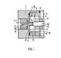
- valve itself is essentially constituted by the valve itself 4 whose central hole is normally closed by the ball 5.
- the valve is formed by a disc with good mechanical properties and sealed, for example made of thin metal. By way of illustration, for a disc whose diameter is of the order of 10 to 30 mm, the disc will have a thickness of the order of 0.10 to 0.40 mm, the ball having a diameter of the order of 1 to 3 mm.
- the disc 4 separates two cavities, preferably cylindrical coaxial, and of different diameters on the side 2 and on the side 3.
- the disc 4 is mounted on the section plane right separating the two cavities of different volumes. It rests against a seal 6 inserted in a circular groove and is glued against a toroidal piezoelectric cell 7 held in place by a locking plug 8 and a circular clip 9 which is placed in a corresponding groove in the body 1.
- a washer 10 d electrical supply is interposed between the piezoelectric toroid 7 and the blocking plug 8. The latter is drilled at 11 to connect the volume 3 and the space 12 between the plug 8 and the disc 4. All of these parts are substantially coaxial.
- the threaded cylindrical part 13 which carries at its end on the valve side a tubular sleeve 14 in which the ball 5 can move axially.
- the bottom of the sleeve 14 is made of hard material, for example a small circular anvil 15 on which the ball can bounce.
- the threaded piece 13 is provided at 16 with any screwing / unscrewing means for adjusting its sinking and therefore the distance between disc 4 and anvil 15 between which the ball moves.
- a lock nut 17 allows the piece to be locked in position threaded 13.
- All of the component parts of the valve are preferably made of non-magnetic materials, with the exception of the ball 5 and the screw 18, the central part of which extends at 20 to receive the O-ring magnet 19.
- Screw 18 and magnet 19 can be made of cobalt and samarium alloys.
- the screw 18 is drilled at 21 to allow communication between the volume 2 and the space 22 located between the disc 4 and the screw 18.
- the adjustment of the screw 18 allows that of the magnetic attraction forces acting as a return of the ball 5 against its seat in the disc 4.
- This seat can be produced for example by electroerosion or by ultrasound which gives sharp edges then we check the edge with a ball of the same diameter as ball 5 to create the seat.
- the radial vibrations of the toroidal cell 7 are reflected by the bulging of the disc 4 by an axial vibration of the central part of the disc and therefore of the seat of the ball 5 which bounces between this seat entering into vibration and the anvil 15.
- the position adjustment of the anvil 15 using the threaded part 13 allows to search conditions for entry into resonance of the ball at a harmonic of the frequency of the piezoelectric cell (of the order of 50 kHz) to give an evaluation by way of illustration.
- the amplitude of vibration of the ball is very low of the order of a few microns (5 to 10 p for example), the accelerations being of the order of a few hundred times that of gravity (250 to 350 g for example ).
- the opening is controlled by sending a train of pulses modulated at the desired frequency.
- the flow rate increases with the duration of the modulation pulse train and by varying the relative duration of the modulation pulse trains and the dead times separating the modulation pulse trains.
- This can be obtained by any conventional circuit, comprising for example an AND gate, receiving on the one hand the excitation frequency and on the other hand the modification slots, followed by the amplifier necessary to have the supply voltage of the piezoelectric cell.
- the admission of gas into chambers 35 and 36 takes place at constant pressure.
- the maximum flow rate of the intake is defined by the limiter 37 which makes it possible to set this maximum flow rate at a value slightly lower than the maximum flow rate offered by the valves 40 and 41.
- valves 40 and 41 By acting on the valves 40 and 41, it is therefore possible to control precise step-by-step movements of the rod 34 and of the devices which it can drive, which in particular makes it possible to perform digital actuation, as soon as pressure differences and no translation of the piston are substantially proportional.
Landscapes
- Engineering & Computer Science (AREA)
- Physics & Mathematics (AREA)
- Fluid Mechanics (AREA)
- Mechanical Engineering (AREA)
- General Engineering & Computer Science (AREA)
- Chemical & Material Sciences (AREA)
- Analytical Chemistry (AREA)
- Electrically Driven Valve-Operating Means (AREA)
- Control Of Fluid Pressure (AREA)
Applications Claiming Priority (2)
| Application Number | Priority Date | Filing Date | Title |
|---|---|---|---|
| FR8302303 | 1983-02-14 | ||
| FR8302303A FR2540945A1 (fr) | 1983-02-14 | 1983-02-14 | Actionneurs a commande numerique |
Publications (1)
| Publication Number | Publication Date |
|---|---|
| EP0118344A1 true EP0118344A1 (de) | 1984-09-12 |
Family
ID=9285879
Family Applications (1)
| Application Number | Title | Priority Date | Filing Date |
|---|---|---|---|
| EP84400271A Withdrawn EP0118344A1 (de) | 1983-02-14 | 1984-02-09 | Digitale Antriebssteuerung |
Country Status (2)
| Country | Link |
|---|---|
| EP (1) | EP0118344A1 (de) |
| FR (1) | FR2540945A1 (de) |
Cited By (5)
| Publication number | Priority date | Publication date | Assignee | Title |
|---|---|---|---|---|
| EP0366605A1 (de) * | 1988-10-25 | 1990-05-02 | GebràDer Sulzer Aktiengesellschaft | Elektrohydraulische oder -pneumatische Stellvorrichtung |
| FR2641829A1 (fr) * | 1989-01-19 | 1990-07-20 | Danfoss As | Servomecanisme commande par un fluide |
| DE19506469C1 (de) * | 1995-02-24 | 1996-04-18 | Honeywell Ag | Doppeltwirkender elektropneumatischer Stellungsregler |
| GB2541485A (en) * | 2016-04-14 | 2017-02-22 | Libertine Fpe Ltd | Actuator module |
| US10662801B2 (en) | 2015-08-21 | 2020-05-26 | Rolls-Royce Plc | Actuator control |
Families Citing this family (1)
| Publication number | Priority date | Publication date | Assignee | Title |
|---|---|---|---|---|
| CN119387552B (zh) * | 2024-10-30 | 2025-07-08 | 肇庆铸技科技有限公司 | 可自动修正的压铸局部加压控制装置 |
Citations (5)
| Publication number | Priority date | Publication date | Assignee | Title |
|---|---|---|---|---|
| US3465732A (en) * | 1967-10-19 | 1969-09-09 | Physics Int Co | Piezoelectric control valve |
| US3537355A (en) * | 1966-12-14 | 1970-11-03 | George N Bliss | Fluid-operated servomechanism |
| DE2446963A1 (de) * | 1974-10-02 | 1976-04-15 | Bosch Gmbh Robert | Stelleinrichtung |
| FR2498285A1 (fr) * | 1981-01-19 | 1982-07-23 | Missioux Jean Leon | Distributeur hydraulique ultra-rapide |
| DE3104704A1 (de) * | 1981-02-10 | 1982-08-26 | Per Henrik Gösta 59030 Borensberg Nyström | "servovorrichtung" |
-
1983
- 1983-02-14 FR FR8302303A patent/FR2540945A1/fr not_active Withdrawn
-
1984
- 1984-02-09 EP EP84400271A patent/EP0118344A1/de not_active Withdrawn
Patent Citations (5)
| Publication number | Priority date | Publication date | Assignee | Title |
|---|---|---|---|---|
| US3537355A (en) * | 1966-12-14 | 1970-11-03 | George N Bliss | Fluid-operated servomechanism |
| US3465732A (en) * | 1967-10-19 | 1969-09-09 | Physics Int Co | Piezoelectric control valve |
| DE2446963A1 (de) * | 1974-10-02 | 1976-04-15 | Bosch Gmbh Robert | Stelleinrichtung |
| FR2498285A1 (fr) * | 1981-01-19 | 1982-07-23 | Missioux Jean Leon | Distributeur hydraulique ultra-rapide |
| DE3104704A1 (de) * | 1981-02-10 | 1982-08-26 | Per Henrik Gösta 59030 Borensberg Nyström | "servovorrichtung" |
Cited By (9)
| Publication number | Priority date | Publication date | Assignee | Title |
|---|---|---|---|---|
| EP0366605A1 (de) * | 1988-10-25 | 1990-05-02 | GebràDer Sulzer Aktiengesellschaft | Elektrohydraulische oder -pneumatische Stellvorrichtung |
| CH675752A5 (de) * | 1988-10-25 | 1990-10-31 | Sulzer Ag | |
| US5148735A (en) * | 1988-10-25 | 1992-09-22 | Danfoss A/S | Electrohydraulic actuator |
| FR2641829A1 (fr) * | 1989-01-19 | 1990-07-20 | Danfoss As | Servomecanisme commande par un fluide |
| DE19506469C1 (de) * | 1995-02-24 | 1996-04-18 | Honeywell Ag | Doppeltwirkender elektropneumatischer Stellungsregler |
| US10662801B2 (en) | 2015-08-21 | 2020-05-26 | Rolls-Royce Plc | Actuator control |
| GB2541485A (en) * | 2016-04-14 | 2017-02-22 | Libertine Fpe Ltd | Actuator module |
| GB2541485B (en) * | 2016-04-14 | 2017-08-23 | Libertine Fpe Ltd | Actuator module |
| US11041512B2 (en) | 2016-04-14 | 2021-06-22 | Libertine Fpe Limited | Actuator module |
Also Published As
| Publication number | Publication date |
|---|---|
| FR2540945A1 (fr) | 1984-08-17 |
Similar Documents
| Publication | Publication Date | Title |
|---|---|---|
| FR2591695A1 (fr) | Amortisseur de vibrations a deux tubes | |
| FR2665497A1 (fr) | Amortisseur de vibrations. | |
| FR2760255A1 (fr) | Dispositif de transmission d'un mouvement, injecteur comportant un tel dispositif et procede d'ajustement d'un tel injecteur | |
| FR2588343A1 (fr) | Systeme d'amortissement d'oscillations avec au moins un amortisseur hydraulique reglable pour vehicules | |
| WO1999037943A1 (fr) | Vanne de reglage de debit | |
| FR2842269A1 (fr) | Amortisseur dynamique de type actif | |
| FR2756006A1 (fr) | Dispositif pour l'actionnement electromagnetique d'une soupape de changement de charge | |
| FR2649465A1 (fr) | Ensemble pour le passage de fluide | |
| EP0118344A1 (de) | Digitale Antriebssteuerung | |
| FR2817605A1 (fr) | Electrovanne proportionnelle pour circuit de liquide de refroidissement de moteur | |
| FR2586222A1 (fr) | Servo de frein pneumatique | |
| FR2689951A1 (fr) | Dispositif de liaison mécanique rigide à coupure de fréquence. | |
| FR2973092A1 (fr) | Dispositif d'obturation, regulateur de pression comportant un tel dispositif, dispositif d'injection diesel comportant un tel regulateur, moteur diesel et vehicule comportant un tel moteur | |
| FR2558913A1 (fr) | Organe de suspension de moteur | |
| FR2509466A1 (fr) | Capteur de deplacement inductif pour organe de reglage fluidique | |
| EP0117195A1 (de) | Elektromagnetisches Ventil mit piezoelektrischer Betätigung | |
| FR2914716A1 (fr) | Butee de compression hydraulique, notamment pour amortisseur hydraulique de suspension de vehicule automobile | |
| WO2016055385A1 (fr) | Injecteur de carburant | |
| EP0378947B1 (de) | Entlüftungsventil | |
| FR2821140A1 (fr) | Valve pneumatique pilotee | |
| FR2595433A1 (fr) | Dispositif de commande de deceleration | |
| FR2809155A1 (fr) | Vanne commandable notamment pour delivrer un debit pulse de fluide | |
| FR2503362A1 (fr) | Dispositif d'etalonnage des capteurs de pression en dynamique | |
| FR2507257A1 (fr) | Dispositif de positionnement | |
| FR2466374A1 (fr) | Regulateur de force de freinage reglable automatiquement en fonction de la charge |
Legal Events
| Date | Code | Title | Description |
|---|---|---|---|
| PUAI | Public reference made under article 153(3) epc to a published international application that has entered the european phase |
Free format text: ORIGINAL CODE: 0009012 |
|
| AK | Designated contracting states |
Designated state(s): AT BE CH DE GB IT LI LU NL SE |
|
| 17P | Request for examination filed |
Effective date: 19850308 |
|
| 17Q | First examination report despatched |
Effective date: 19860127 |
|
| STAA | Information on the status of an ep patent application or granted ep patent |
Free format text: STATUS: THE APPLICATION HAS BEEN WITHDRAWN |
|
| 18W | Application withdrawn |
Withdrawal date: 19860416 |
|
| RIN1 | Information on inventor provided before grant (corrected) |
Inventor name: GUILLEMOT, PHILIPPE |