EP0118383A2 - Verbindungsteil zur Temperaturverminderung im Bereich der Schaltertafel von Haushaltsherden - Google Patents
Verbindungsteil zur Temperaturverminderung im Bereich der Schaltertafel von Haushaltsherden Download PDFInfo
- Publication number
- EP0118383A2 EP0118383A2 EP84440002A EP84440002A EP0118383A2 EP 0118383 A2 EP0118383 A2 EP 0118383A2 EP 84440002 A EP84440002 A EP 84440002A EP 84440002 A EP84440002 A EP 84440002A EP 0118383 A2 EP0118383 A2 EP 0118383A2
- Authority
- EP
- European Patent Office
- Prior art keywords
- box
- control panel
- air
- walls
- association according
- Prior art date
- Legal status (The legal status is an assumption and is not a legal conclusion. Google has not performed a legal analysis and makes no representation as to the accuracy of the status listed.)
- Withdrawn
Links
Images
Classifications
-
- F—MECHANICAL ENGINEERING; LIGHTING; HEATING; WEAPONS; BLASTING
- F24—HEATING; RANGES; VENTILATING
- F24C—DOMESTIC STOVES OR RANGES ; DETAILS OF DOMESTIC STOVES OR RANGES, OF GENERAL APPLICATION
- F24C15/00—Details
- F24C15/006—Arrangements for circulation of cooling air
Definitions
- the present invention relates to a combination of means intended to reduce the temperature at the level of the control panel in so-called electronic domestic ovens, that is to say those comprising active electronic components for controlling their operation.
- the invention applies to all domestic ovens. It is particularly advantageous in 1 pyrolysis ovens in which the carbonization temperature reaches 500 ° C.
- the main purpose of this invention is to allow the use of such components cost much lower than those specially manufactured for advanced techniques using parts subjected to significant thermal stresses.
- the present invention aims to remedy these drawbacks and, to this end, it relates to a combination of means intended to reduce the temperature at the level of the control panel so as to allow the use of electronic components of large series, of low cost and supply easy, fast and certain.
- the combination of means according to the invention is characterized in that it comprises a linear air inlet provided between the lower edge of the control panel and the linear mouth for diffusing the extracted air as well as a box with conductive walls. protecting the rear of the control panel by creating a closed volume thermally insulated by cooling its walls with the flow of fresh air admitted.
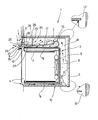
- the oven shown, reference 1 conventionally comprises an enclosure 2 or muffle fixed .. suitably on a carcass 3 serving as a body.
- the oven is closed at the front by a tilting door 4 locked by a retractable handle 5.
- the oven will include a floor heating resistor 6, a roof heating resistor 7 and a rear fan 8 with its peripheral resistance 9
- the carcass is placed in a cabinet 10, the walls 11 of which form an almost closed volume. As the case may be, this volume is opened by its rear face according to top 12 and bottom 13 passages forming a chimney.
- a group of aspira-; centrifugal tion 15 which draws in the interior air from the bottom to discharge it to the outside by a flat duct 16 formed by two converging walls 17 and 18 opening to the outside by a linear diffusion mouth 19 arranged under the lower edge 20 of the control panel 21.
- the extracted air comes not only from the different openings provided in the carcass, but also from the top and bottom passages 12 and 13.
- a linear air inlet 22 disposed between the lower edge of the strip 21 and the linear diffusion mouth 19 through which the extracted air is discharged.
- This air inlet also makes it possible to ensure sufficient air flow in front of the control panel 21 to participate in the conduction cooling.
- a closed box 23 sealingly defining a stationary air volume 24 at the rear of the control panel 21.
- This box comprises a vertical wall 25 parallel to the strip 21 and a horizontal wall 26 delimiting with the upper wall 17 from the flat ejection duct 16, a shallow flat channel 27 for the passage of admitted fresh air.
- the box 23 is closed laterally to produce a completely stationary air volume.
- the fresh air benefits in addition to the separation by the insulation curtain formed by the air stream 28 leaving the exhaust outlet 19. This insulation avoids the mixing of the heated air in contact with the front face of door 4 with the fresh air coming from the upper space and admitted by the air inlet 22.
- the path of the fresh air continues towards the suction unit 15, a path during which it forms a curtain of thermal insulation sufficient to protect the vertical wall 25 of the box from temperature rises.
- the box 23 is therefore perfectly isolated from the superheated air.
- the internal temperature of the volume of occluded air will not exceed the resistance limit of current electronic components, even in the phase of carbonization of fatty residues during which the temperature of the enclosure reaches 500 ° C.
Landscapes
- Engineering & Computer Science (AREA)
- Chemical & Material Sciences (AREA)
- Combustion & Propulsion (AREA)
- Mechanical Engineering (AREA)
- General Engineering & Computer Science (AREA)
- Electric Stoves And Ranges (AREA)
- Baking, Grill, Roasting (AREA)
Applications Claiming Priority (2)
| Application Number | Priority Date | Filing Date | Title |
|---|---|---|---|
| FR8301915 | 1983-02-04 | ||
| FR8301915A FR2540607B1 (fr) | 1983-02-04 | 1983-02-04 | Association de moyens pour reduire la temperature au niveau du bandeau de commande dans les fours domestiques |
Publications (2)
| Publication Number | Publication Date |
|---|---|
| EP0118383A2 true EP0118383A2 (de) | 1984-09-12 |
| EP0118383A3 EP0118383A3 (de) | 1985-10-30 |
Family
ID=9285677
Family Applications (1)
| Application Number | Title | Priority Date | Filing Date |
|---|---|---|---|
| EP84440002A Withdrawn EP0118383A3 (de) | 1983-02-04 | 1984-02-03 | Verbindungsteil zur Temperaturverminderung im Bereich der Schaltertafel von Haushaltsherden |
Country Status (2)
| Country | Link |
|---|---|
| EP (1) | EP0118383A3 (de) |
| FR (1) | FR2540607B1 (de) |
Cited By (6)
| Publication number | Priority date | Publication date | Assignee | Title |
|---|---|---|---|---|
| FR2618529A1 (fr) * | 1987-07-24 | 1989-01-27 | Dietrich & Cie De | Circuit de ventilation supplementaire pour four electro-domestique combine |
| GB2212902A (en) * | 1987-11-25 | 1989-08-02 | Valor Electrical Limited | Cookers |
| FR2681127A1 (fr) * | 1991-09-06 | 1993-03-12 | Europ Equip Menager | Dispositif de refroidissement de la porte d'un appareil de cuisson. |
| US5193520A (en) * | 1991-05-01 | 1993-03-16 | Stoves Limited | Cooking apparatus |
| GB2349457A (en) * | 1999-04-30 | 2000-11-01 | Stoves Group Plc | Cooking appliance |
| EP1795812A3 (de) * | 2005-12-12 | 2016-12-28 | LG Electronics Inc. | Kochgerät |
Family Cites Families (5)
| Publication number | Priority date | Publication date | Assignee | Title |
|---|---|---|---|---|
| US3911893A (en) * | 1974-06-24 | 1975-10-14 | White Westinghouse Corp | Ventilating system for self-cleaning wall oven |
| DE2615604C3 (de) * | 1976-04-09 | 1979-02-01 | Bosch-Siemens Hausgeraete Gmbh, 7000 Stuttgart | Backofen, insbesondere mit Mitteln zur pyrolytischen Reinigung mit einem Kühlluftgebläse |
| DE3028262C1 (de) * | 1980-07-25 | 1982-07-22 | Bosch-Siemens Hausgeräte GmbH, 7000 Stuttgart | Kochgeraet,insbesondere Herd |
| DE8034134U1 (de) * | 1980-12-22 | 1981-05-27 | Bosch-Siemens Hausgeräte GmbH, 7000 Stuttgart | Backofen |
| DE3104677A1 (de) * | 1981-02-10 | 1982-08-12 | Bosch Siemens Hausgeraete | Backofen, vorzugsweise mit einer thermischen heizeinrichtung sowie mit einer mikrowellen-heizeinrichtung |
-
1983
- 1983-02-04 FR FR8301915A patent/FR2540607B1/fr not_active Expired
-
1984
- 1984-02-03 EP EP84440002A patent/EP0118383A3/de not_active Withdrawn
Cited By (8)
| Publication number | Priority date | Publication date | Assignee | Title |
|---|---|---|---|---|
| FR2618529A1 (fr) * | 1987-07-24 | 1989-01-27 | Dietrich & Cie De | Circuit de ventilation supplementaire pour four electro-domestique combine |
| GB2212902A (en) * | 1987-11-25 | 1989-08-02 | Valor Electrical Limited | Cookers |
| US5193520A (en) * | 1991-05-01 | 1993-03-16 | Stoves Limited | Cooking apparatus |
| FR2681127A1 (fr) * | 1991-09-06 | 1993-03-12 | Europ Equip Menager | Dispositif de refroidissement de la porte d'un appareil de cuisson. |
| EP0532393A1 (de) * | 1991-09-06 | 1993-03-17 | Compagnie Europeenne Pour L'equipement Menager "Cepem" | Kühlvorrichtung für Backofentür |
| GB2349457A (en) * | 1999-04-30 | 2000-11-01 | Stoves Group Plc | Cooking appliance |
| GB2349457B (en) * | 1999-04-30 | 2001-07-25 | Stoves Group Plc | A cooking appliance |
| EP1795812A3 (de) * | 2005-12-12 | 2016-12-28 | LG Electronics Inc. | Kochgerät |
Also Published As
| Publication number | Publication date |
|---|---|
| EP0118383A3 (de) | 1985-10-30 |
| FR2540607A1 (fr) | 1984-08-10 |
| FR2540607B1 (fr) | 1989-02-03 |
Similar Documents
| Publication | Publication Date | Title |
|---|---|---|
| EP0154595B1 (de) | Elektrischer Katalysator-Haushaltsherd mit Vorrichtung um die Ofenkammer in Unterdruck zu bringen und zu halten | |
| US3529582A (en) | Self-cleaning forced convection oven | |
| EP1544547B1 (de) | Elektrischer Ofen mit Kühlanlage für Tür | |
| FR2472142A1 (fr) | Four comportant un element de chauffage de gril et au moins un autre element de chauffage ainsi qu'un ventilateur de circulation d'air | |
| SE501130C2 (sv) | Varmluftsugn för matberedning i hetluft med kylning av ytor och kontroll av ånghalt | |
| FR2545586A1 (fr) | Four electrique auto-nettoyant perfectionne | |
| US3678245A (en) | Device for cleaning the walls of the muffle chamber of baking and roasting ovens | |
| EP0118383A2 (de) | Verbindungsteil zur Temperaturverminderung im Bereich der Schaltertafel von Haushaltsherden | |
| JP7229797B2 (ja) | 加熱調理器 | |
| FR2463364A1 (fr) | Cuisiniere dont les parties de commande sont protegees de la chaleur du four | |
| FR2618529A1 (fr) | Circuit de ventilation supplementaire pour four electro-domestique combine | |
| FR2731065A1 (fr) | Dispositif de cuisson | |
| CN211609364U (zh) | 一种蛋糕机 | |
| KR20200012307A (ko) | 조리기기 | |
| EP0511052B1 (de) | Backrohr | |
| FR2748796A1 (fr) | Dispositif de refroidissement d'un ensemble de cuisson domestique | |
| JPH03191215A (ja) | 加熱調理器 | |
| CN217218787U (zh) | 一种具有新型加热结构的电烤箱 | |
| FR2548764A1 (fr) | Four electrique a usage menager | |
| EP0161161A1 (de) | Kochraum mit elektrischer Beheizung | |
| JP2005351563A (ja) | 蒸気調理器 | |
| EP0271392B1 (de) | Feststoffbefeuerter Heizkessel und insbesondere Holzbefeuerter Heizkessel | |
| EP1193452B1 (de) | Steuerelektronik für Kochgeräte | |
| KR102856594B1 (ko) | 원두 로스팅용 드럼로스터 | |
| FR2517810A1 (fr) | Four electrique de cuisson a usage menager |
Legal Events
| Date | Code | Title | Description |
|---|---|---|---|
| PUAI | Public reference made under article 153(3) epc to a published international application that has entered the european phase |
Free format text: ORIGINAL CODE: 0009012 |
|
| AK | Designated contracting states |
Designated state(s): BE DE GB IT NL |
|
| 17P | Request for examination filed |
Effective date: 19850225 |
|
| PUAL | Search report despatched |
Free format text: ORIGINAL CODE: 0009013 |
|
| AK | Designated contracting states |
Designated state(s): BE DE GB IT NL |
|
| 17Q | First examination report despatched |
Effective date: 19860522 |
|
| STAA | Information on the status of an ep patent application or granted ep patent |
Free format text: STATUS: THE APPLICATION IS DEEMED TO BE WITHDRAWN |
|
| 18D | Application deemed to be withdrawn |
Effective date: 19890519 |
|
| RIN1 | Information on inventor provided before grant (corrected) |
Inventor name: GUERIN, JACKY |