EP0118574A1 - Beleuchtungskörper für Reklametafel - Google Patents
Beleuchtungskörper für Reklametafel Download PDFInfo
- Publication number
- EP0118574A1 EP0118574A1 EP83102336A EP83102336A EP0118574A1 EP 0118574 A1 EP0118574 A1 EP 0118574A1 EP 83102336 A EP83102336 A EP 83102336A EP 83102336 A EP83102336 A EP 83102336A EP 0118574 A1 EP0118574 A1 EP 0118574A1
- Authority
- EP
- European Patent Office
- Prior art keywords
- billboard
- lamp
- lighting fixture
- reflector
- refractor
- Prior art date
- Legal status (The legal status is an assumption and is not a legal conclusion. Google has not performed a legal analysis and makes no representation as to the accuracy of the status listed.)
- Granted
Links
- 238000004140 cleaning Methods 0.000 claims description 3
- 238000005286 illumination Methods 0.000 description 8
- 239000011521 glass Substances 0.000 description 7
- 238000000034 method Methods 0.000 description 3
- 238000012360 testing method Methods 0.000 description 3
- 238000013459 approach Methods 0.000 description 2
- 230000003287 optical effect Effects 0.000 description 2
- 238000012552 review Methods 0.000 description 2
- 238000005452 bending Methods 0.000 description 1
- 230000015572 biosynthetic process Effects 0.000 description 1
- 230000007812 deficiency Effects 0.000 description 1
- 238000013461 design Methods 0.000 description 1
- 239000006185 dispersion Substances 0.000 description 1
- 230000000694 effects Effects 0.000 description 1
- 238000004134 energy conservation Methods 0.000 description 1
- 230000004907 flux Effects 0.000 description 1
- 229910001507 metal halide Inorganic materials 0.000 description 1
- 150000005309 metal halides Chemical class 0.000 description 1
Images



Classifications
-
- G—PHYSICS
- G09—EDUCATION; CRYPTOGRAPHY; DISPLAY; ADVERTISING; SEALS
- G09F—DISPLAYING; ADVERTISING; SIGNS; LABELS OR NAME-PLATES; SEALS
- G09F13/00—Illuminated signs; Luminous advertising
- G09F13/02—Signs, boards, or panels, illuminated by artificial light sources positioned in front of the insignia
Definitions
- This invention relates generally to a lighting fixture and more particularly to a new and novel outdoor lighting fixture for use in illuminating a large poster panel such as an outdoor advertising billboard sign of the type that is generally 12 1 high and 24 1 long.
- prior art illumination would be accomplished by a pair of eight foot long flourescent units positioned end-to-end either below or above the panel.
- Other types of prior art lighting would include a grouping of single incandescent units positioned along the top or bottom edges of the panel.
- a new and novel single lighting fixture designed for mounting in front of a large outdoor advertising panel.
- the fixture is capable of providing uniform illumination across the entire panel length even when the panel has a horizontal length approximately two times as long as its vertical length.
- the new and novel lighting fixture may be mounted in the central portion of the advertising sign either above or below the sign as hereinafter described.
- the new and novel lighting fixture comprises a generally horizontally positioned lamp contained within a lamp housing which is mounted on the outside of the advertising sign.
- the housing contains a lamp energized by known means for lighting the lamp and also contains a reflector which is positioned on one side of the lamp and is designed to reflect the light radiating from the lamp.
- the reflector ⁇ has a first generally linearly translated parabolic surface and further has two side surfaces formed parabolic in one direction through a horizontal section of the side surface.
- a refractor is positioned over the lamp in the lamp housing to totally enclose the lamp from outside weather elements and the refractor comprises in part a combination of prism elements which are designed for three phase light control of stray light.
- the three phase light control permits a refraction, a reflection and finally a refraction of the stray light radiating from the lamp.
- the unit is able-to illuminate the opposite adjacent corners of the billboard to provide a much more uniform light distribution pattern over the entire elongated billboard surface than has been heretofor possible with prior art devices.
- Yet another object and advantage of the invention is to provide a simple lighting fixture which is capable of being used as a single fixture and is capable of being positioned in the upper or lower area of a billboard with the fixture combining a new and novel reflector and refractor for directing the light in pre-determined manners to achieve more uniform illumination over the panel.
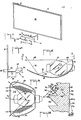
- FIGS. land 2 of the drawings there is shown the Applicant's new and novel lighting fixture, shown generally by the numeral 10, as it is fastened to a outdoor billboard 12 by means of a pipe 14 or some other fastening device.
- the lighting fixture comprises a lamp housing 16 formed as shown in the figures and having a refractor 18 in position on the housing 16 in such a manner to totally enclose the lamp 20 contained within the housing 16.
- the lighting fixture 10 may be mounted in the position shown in FIG. 1 and may also be mounted on the upper portion of the billboard 12 in the central area in a manner similiar shown in the mounting shown in FIG. 1.
- the area to be lighted by the lamg 20 would include the entire surface 22 shown in FIG. 1 in as uniform a manner as possible without eye disturbing lighting contrasts in the various areas of the panel.
- positioning the lighting fixture 10 it has been found from experimentation that it would be preferably positioned between 31 ⁇ 2-4' from the billboard as shown by the arrow 24 and also would be preferably positioned approximately 1' below the billboard edge 26 as shown by the arrow 28. When positioned thusly it has been found that the area to be lighted 22 would have a much more uniform illumination thereby providing a more pleasant eye appealing advertising sign placed on the surface area 22.
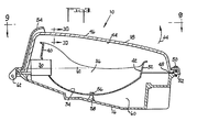
- FIG. 3 of the drawing there is shown in detail, a cross sectional view, taken along 3-3 of the FIG. 1, showing the interior of the Applicant's lighting fixture 10.
- a lamp 20 is positioned in a lamp socket 30 so as to be approximately horizontally positioned within the lamp housing 16.
- the lamp 20 is not shown in FIG. 3 and also the means for lighting the lamp such as the associated wiring and power necessary for the high intensity discharge type lamp is not shown.
- a reflector 32 is positioned on one side of the lamp and is designed to reflect the light radiating from the lamp hereinafter described.
- the reflector 32 has a first generally linear translated parabolic bottom surface 34 and has two side surfaces 36 and 38 which are formed parabolic in one direction through a horizontal section of the side surface.
- the generally linear parabolic bottom surface 34 is formed in the configuration shown in FIG. 3 and also comprises the substantially parallel end surfaces 40 and 42 shown in FIG. 3 and also more clearly in FIG. 5 of the drawing.
- a refractor 18 is positioned on the lamp housing 16 to totally enclose the lamp 20 from outside weather elements.
- the refractor 18 comprises a combination of prism elements to be described more fully hereinafter which are designed for three phase light control of stray light.
- the refractor 18 is designed to refract, reflect and finally to refract the stray light radiating from the lamp 20.
- the prism elements are formed on the inside surface 44 of the refractor with the outside surface 46 being formed relatively smooth in order to allow the refractor 18 to be self cleaning.
- the refractor 18 is positioned within the lamp housing 16 and is held in place on a gasket 48 by means of a plurality of bolts 50 through a plurality tapped holes formed in the flange 52 of the housing 16.
- the housing 16 also contains a shield 54 which is designed to partially enclose the refractor 18 and to shield stray light from the rear portion of the refractor which will not be able to be redirected by the refractor prisms.
- the reflector 32 is fixedly held inside the lamp housing 16 by means of a screw 56 tapped in a boss 58 on the inside area 60 of the lamp housing 16.
- the entire refractor 18 along with the shield 54 is capable of being pivoted upwardly about the pins 62 whenever it is desirous of having access to the inside of the lamp housing.
- the refractor 18 and the shield 54 may be pivoted upwardly in the direction shown by the arrow 64 to provide the interior access to the lighting fixture.
- FIG. 4 and FIG. 5 of the drawings there is shown positioned inside the reflector 32 the lamp 20 and showing how the various rays of the lamp are controlled to light various portions of the billboard panel. It can be seen in FIG. 4 how a ray 66 would be reflected off the end surface 40 in the direction shown by the arrow 68 to light the bottom of the poster panel. In a similiar manner a forward directed light ray 70 would be reflected off the bottom surface 34 to be directed upwardly in the direction of the arrow 72 to light the top of the poster panel.
- FIGS. 6, 7 and 8 there will be shown in more detail how the edges of the poster panel are lighted and more particularly how the triangularly shaped corner areas of the panel are lighted.
- FIG. 8 there is shown a side view of the surface area 22 to be lighted.
- the cross section area 78 shown in FIG. 8 is the approximate area which is lighted by the bottom surface 34 of the Applicant's reflector 32 and represents the area that prior art type of reflector lights were capable of lighting.
- the triangular shaped areas 80, 82, 84 and 86 represent the areas which are lighted by side surfaces 36 and 38 of the Applicant's reflector 32.
- FIG. 6 and 7 there can be seen how the reflector side surfaces 36 and 38 are utilized to accomplish the lighting of the corner areas.
- FIG. 6 there can be seen the plan view showing the side surfaces 36 and 38 and how they are utilized to direct the rays 92 and 94 in the direction shown by the arrows 96 and 98 to the left corner edges of the billboard 12.
- the rays directed to the side surface 36 have not been shown in FIG. 6 and it should become apparent that the side surface 36 would direct light rays to the right edges of the billboard 12.
- FIG. 7 is an end view of the Applicant's lighted billboard showing the positioning of the side surfaces 36 and 38 how the ray 100 from the lamp 20 would be directed against the sides of the side surface 38 of the reflector 32 to be redirected in the direction shown by the arrow 102.
- the ray 104 would be redirected to light the central portions of the edges of the billboard in the direction of the arrow 106.
- the ray 108 would be redirected by the side surface 38 in the direction by the arrow 110 to illuminate the upper portion of the triangular edges of the billboard.
- the left side surface 36 would be used to redirect the rays from the lamp 20 to light the right side of the billboard 12.
- the bumps 110 and 112 may be utilized to eliminate radial streaks 114 and 116 which are shown in FIG. 7 of the drawing by the dashed lines.
- the bumps 110 and 112, shown in FIG. 5 of the drawing would be formed by truncated spheres having a +10° or -10° slope upwardly and would be formed as upward positioned bumps which provide a +20° or -20° light dispersion on each side of the radial streak area 114 and 116 to thereby eliminate the radial streak.
- any horizontal plane passing through the end surfaces 40 and 42 will yield an intersection approximating a parabola with its focus at the light center (L. C.) and its axis pointing towards the edge of the billboard sign on the end of the billboard sign opposite the reflector end.
- a cross-over occurs and this is illustrated in FIG. 6 of the drawing by the angle shown by the arrow 118 which would be approximately 66° when the housing is positioned as hereinbefore described.
- the vertical distribution of the light along the edges 120 and 122 of the billboard sign is accomplished through the curvature of the reflector 32 in its vertical planes.
- the top edge of the vertical planes directs the light to the bottom corners of the sign and the bottom edge of the reflector sections directs the light to the top edge 124 of the billboard sign.
- Approximately 30% of the vertical section is devoted to lighting the bottom corners of the sides since this area is the hardest to light due to light having to exit glass at extremely high angles of incidence and due to physical restrictions often not permitting the light to get there from a mechanical constraint standpoint.
- the remainder of the side panel areas representing 70% of said side panels are designed to evenly light the entire height of the edge of the sign.
- the bottom boundary of the reflector side surfaces 36 and 38 is determined by the design of the bottom surface 34 and end surfaces 40 and 42 of the bottom surface 34.
- the top boundary is contoured to prevent interference with direct and reflected light which is utilized on the sign surface 22.
- the refractor 18 is designed with a combination of prism elements which are designed for three phase light control of stray light to redirect the stray light to the billboard panel.
- the refractor 18 could be considered an optical component of the luminaire whereby its use, the luminous flux from the light source and, in some cases from the reflector, is redirected in varying amounts to achieve a final high degree of uniformity of illumination on the poster panel.
- the outside surface 46 of the refractor 18 has been formed relatively smooth so that it would be totally self cleaning.
- the inside surface 44 of the refractor 18 is then devoted to the optical control desired. Sections of the refractor may be left plain where directed light is not desired or required. Referring to FIG. 10 of the drawing, there is shown a cross sectional view taken along line 10-10 of FIG. 3 shewing the three phase light control by the use of the various prism elements of the refractor 18.
- the entire surface of the refractor was broken into squares and the light going through each square was analyzed and if needed was redirected by order of the various prisms on the inside surface of the refractor.
- this A 1 ray hits surface S 2 of the prism.
- This S 2 surface is approximately vertically oriented and the ray in the glass hits the surface S 2 and reflects such that the angle of incidence "i", shown by the arrow 134 in respect to the normal to S 2 (label N S 2 ) is equal to the angle of reflection "r" shown by the arrow 136 as an angle in the glass G2.
- the angle in the glass G2 represented by the numeral 138 then strikes the top surface of the refractor S 3 represented by the numeral 130 and is transmitted out and refracted in the process as the ray A 2 sham by the numeral 140.
- the ray A 2 is of such an angle that is strikes the poster panel in a location designed to improve the uniformity of light on the poster panel and to improve utilization of light on the sign.
- the angle A 2 depends upon the angle at which G2 strikes the normal to the surface S 3 and is calculable by Snells law governing refraction of light as it enters or leaves the media with varying indices of refraction. Air is approximately 1.0 index of refraction, and glass is approximately 1.5 index of refraction.
- n 1 Sin °1 n 2 sin °2 I
- the n 1 and n 2 are the index of refraction of medium 1 and medium 2 respectively.
- a 1 does not have to be perpendicular to the surace S 1 , but the whole prism structure, including the surface S 1 and surface S 2 must be so designed so that the exiting ray A 2 goes in the right direction. The closer A 1 is perpendicularly with S 1 , the higher the efficiency of the prismatic structure.
- Lateral control of the before described light control is accomplished by calculating the appropriate prism path or direction of proper lateral placement of the existing A 2 on the poster panel.
- Proper vertical Genevament of the light on the poster panel is accomplished by varying the depths of the prisms which, in effect, means varying the angle between the prism face S 1 and the prism face 5 2 .
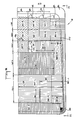
- FIG. 9 of the drawing there is shown a plan view of 1 ⁇ 2 of the Applicant's refractor 18.
- the plurality of prism elements will now be described and the process for redirecting the stray light resulting in the various sections shown in the FIG. 9 drawing will be seen.
- the section A prism is positioned approximately 381 ⁇ 2° as shown by the angle 142 and the prism size would be approximately 2" x 2" as shown by the numerals 144 and 146.
- the prism section B would be positioned at an angle of approximately 29° as shown by the angle 148 in the drawings.
- the prism section B would also be sized approximately 2" x 2" as shown by the numerals 144 and 150.
- the prism section C would be angled approximately 14° as shown by the angle 152 and the prism section would be sized approximately 2'' x 2" as shown by the numerals 144 and 154.
- Prism section E would be angled approximately 35.5°as shown by the angle 156 and would also be sized approximately 2" x 2" as shown by the numeral 158 and 146.
- the prism section D would be formed parallel to the front and rear edges of the refractor as shown in FIG. 9.
- the prism section F would be angled approximately 16° as shown by the angle 160 and would also be sized approximately 2" x 2" as shown by the numeral 158 and 150.
- the prism section G and H would be positioned as shown in the drawing approximately parallel to the ends of the refractor mold and would also be sized approximately 2" x 2" as shown by the numerals 158, 154 and 162.
- Section I prisms would be angled approximately 15° as shown by the numeral 164 and that prism section would be sized approximately 2" x 2" as shown by the numeral 146 and 166.
- the section K group of prisms and the P group of prisms are positioned approximately parallel to the front face of the mold as shown.
- the section K would be sized approximately 4" x 7" as shown by the numerals 167 and 169.
- the section P would be sized approximately 2" x 3.75" as shown by the numerals 166 and 171.
- the area shown by the numeral 170 may remain plain and unpolished as shown.
- Section L prisms would be formed approximately parallel to the front and rear edges of the refractor and would be approximately 5" long by 8" long as shown by the numerals 176 and 178.
- the section M group of prisms would be formed were shown in FIG. 9 of the drawing approximately parallel to the section L prisms and would be approximately 21 ⁇ 2" x 4" in size as shown by the numerals 180 and 182.
- the section Q prisms would be positioned as shown adjacent to the prism groups M, N and J.
- a front wall grouping of prisms section N would be formed as shown in the FIG. 9 drawing and a side section of prisms J would also be formed in the manner shown.
- the remaining portion of the side wall of the refractor would consist of section D prisms formed as designated on the drawing.
- a radial corner cut set of prisms shown by the numeral 184 fills in one pair of corners and the remaining wall section shown by the numeral 186 would be sandblasted to a heavy texture as is known in the art.
- a prism section 0 would be cut parallel to the line 175 as shown in FIG. 9.
- prisms section A, B, C, D, E, F, G and B are utilized for the stray light control and are designed for the three phase light control hereinbefore described consisting of refraction, reflection and refraction as related to FIG. 10 of the drawings.
- the other half of the refractor as shown in FIG. 9 would be a duplicate of FIG. 9 as shown.
- FIG. 11 of the drawing there is sham a side view, taken along line 11-11 of FIG. 9, showing the plurality of prism elements positioned along the sides of the refractor 18.
- section H prism elements run into the side surface adjacent to the section D prisms which also run into the upper surface as shown in FIG. 9.
- Adjacent to section D prisms would be a grouping of prism elements section J shown also in FIG. 9 which is utilized to smooth out light passing through that section of the prism.
- section K shown in FIG. 9 is also used to smooth out light caused by imperfections in reflection or in the tooled surface of the refractor.
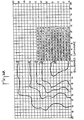
- FIG. 9 there is shown an analysis of the footcandles developed by the Applicant's new and novel lighting fixture in comparison to the footcandles developed by a-prior art type fixture.
- the Applicant's fixture is shown in FIG. 12 of the drawing with a competitors prior art fixture shown in FIG. 13.
- the Applicant's test data was taken from a test numbered 34,618 having the tested luminaire placed 4 1 out and 1' down from the bottom of the billboard structure.
- the competitors' data was taken from a test numbered 32,489 with the competitors luminaire placed 4 1 out from the sign.
- the average foot candles for the Applicant's luminaire as shown in FIG. 12 was 28.5 in comparison to the competitors average foot candle of 22.
- the Applicant's maximum foot candle was 94.12 as compared to the maximum foot candle of 102 for the competitor.
- a minimum footcandle value of 4.37 was tested in the Applicant's luminaire with a minimum footcandle value of 0 in the competitors'.
- the maximum to minimum footcandle ratio of the Applicant's luminaire was 21.53 and the maximum to average ratio was 3.35 with the average to minimum ratio being 6.42.
- the maximum to minimum footcandle of the competitors' luminaire was .1830 with a maximum to average ratio of 5 and average to minimum ratio of 405. A perfect ratio would be 1 when comparing these numbers.
- the Applicant's luminaire with its new and novel features provides a more uniformally lighted billboard surface so that the sign placed upon the billboard surface would appear to be more uniformly lighted without great variations in luminance which is the light leaving the surface of the billboard.
- the Appliant's new and novel invention utilizes a combination of a high intensity discharge lamp positioned in a lamp housing with a new and novel reflector and refractor positioned within the housing to achieve the desired lighting in the various areas of the billboard.
Landscapes
- Physics & Mathematics (AREA)
- General Physics & Mathematics (AREA)
- Engineering & Computer Science (AREA)
- Theoretical Computer Science (AREA)
- Illuminated Signs And Luminous Advertising (AREA)
- Arrangement Of Elements, Cooling, Sealing, Or The Like Of Lighting Devices (AREA)
Priority Applications (4)
| Application Number | Priority Date | Filing Date | Title |
|---|---|---|---|
| AT83102336T ATE45640T1 (de) | 1983-03-10 | 1983-03-10 | Beleuchtungskoerper fuer reklametafel. |
| DE8383102336T DE3380424D1 (en) | 1983-03-10 | 1983-03-10 | Poster panel lighting fixture |
| EP83102336A EP0118574B1 (de) | 1983-03-10 | 1983-03-10 | Beleuchtungskörper für Reklametafel |
| DE198383102336T DE118574T1 (de) | 1983-03-10 | 1983-03-10 | Beleuchtungskoerper fuer reklametafel. |
Applications Claiming Priority (1)
| Application Number | Priority Date | Filing Date | Title |
|---|---|---|---|
| EP83102336A EP0118574B1 (de) | 1983-03-10 | 1983-03-10 | Beleuchtungskörper für Reklametafel |
Publications (2)
| Publication Number | Publication Date |
|---|---|
| EP0118574A1 true EP0118574A1 (de) | 1984-09-19 |
| EP0118574B1 EP0118574B1 (de) | 1989-08-16 |
Family
ID=8190335
Family Applications (1)
| Application Number | Title | Priority Date | Filing Date |
|---|---|---|---|
| EP83102336A Expired EP0118574B1 (de) | 1983-03-10 | 1983-03-10 | Beleuchtungskörper für Reklametafel |
Country Status (3)
| Country | Link |
|---|---|
| EP (1) | EP0118574B1 (de) |
| AT (1) | ATE45640T1 (de) |
| DE (2) | DE3380424D1 (de) |
Cited By (1)
| Publication number | Priority date | Publication date | Assignee | Title |
|---|---|---|---|---|
| GB2241814A (en) * | 1990-03-08 | 1991-09-11 | Haldo Dev Ltd | Illumination of a surface. |
Citations (4)
| Publication number | Priority date | Publication date | Assignee | Title |
|---|---|---|---|---|
| US3524051A (en) * | 1968-08-19 | 1970-08-11 | Gen Electric | Luminaire |
| US4037341A (en) * | 1973-08-13 | 1977-07-26 | Johns-Manville Corporation | Luminaire for lighting a sign and method |
| US4148561A (en) * | 1976-05-19 | 1979-04-10 | Ludwig Eigenmann | Method for producing improved retroreflective system for sign surfaces, and improved systems produced thereby |
| US4262326A (en) * | 1979-03-16 | 1981-04-14 | K-S-H, Inc. | Lens for high intensity lamp fixtures |
-
1983
- 1983-03-10 EP EP83102336A patent/EP0118574B1/de not_active Expired
- 1983-03-10 AT AT83102336T patent/ATE45640T1/de not_active IP Right Cessation
- 1983-03-10 DE DE8383102336T patent/DE3380424D1/de not_active Expired
- 1983-03-10 DE DE198383102336T patent/DE118574T1/de active Pending
Patent Citations (4)
| Publication number | Priority date | Publication date | Assignee | Title |
|---|---|---|---|---|
| US3524051A (en) * | 1968-08-19 | 1970-08-11 | Gen Electric | Luminaire |
| US4037341A (en) * | 1973-08-13 | 1977-07-26 | Johns-Manville Corporation | Luminaire for lighting a sign and method |
| US4148561A (en) * | 1976-05-19 | 1979-04-10 | Ludwig Eigenmann | Method for producing improved retroreflective system for sign surfaces, and improved systems produced thereby |
| US4262326A (en) * | 1979-03-16 | 1981-04-14 | K-S-H, Inc. | Lens for high intensity lamp fixtures |
Cited By (1)
| Publication number | Priority date | Publication date | Assignee | Title |
|---|---|---|---|---|
| GB2241814A (en) * | 1990-03-08 | 1991-09-11 | Haldo Dev Ltd | Illumination of a surface. |
Also Published As
| Publication number | Publication date |
|---|---|
| EP0118574B1 (de) | 1989-08-16 |
| DE118574T1 (de) | 1985-02-14 |
| DE3380424D1 (en) | 1989-09-21 |
| ATE45640T1 (de) | 1989-09-15 |
Similar Documents
| Publication | Publication Date | Title |
|---|---|---|
| US4451875A (en) | Poster panel lighting fixture | |
| US5542201A (en) | Indirectly illuminated sign | |
| KR100811061B1 (ko) | 고휘도 엘이디를 이용한 조명기구 | |
| US5075827A (en) | Indirect light fixture amplification reflector system | |
| US4698734A (en) | Lensed indirect luminaire with side angle brightness control | |
| US8485684B2 (en) | LED roadway luminaire | |
| US3020395A (en) | Lighting device | |
| US5278737A (en) | Wall and ceiling lighting unit | |
| US4729075A (en) | Constant zone reflector for luminaires and method | |
| US5997156A (en) | Lighting device for generating a rectangular pattern at the work area, E. G. for illuminating pedestrian crossings | |
| US20010048599A1 (en) | Light distributor for a lighting device and lighting device and use of a lighting device | |
| US4954935A (en) | Lighting system for illuminating billboards and the like | |
| US4349866A (en) | Light reflection system with asymmetric reflector assembly | |
| BG108099A (bg) | Устройство за изображение на данни | |
| US4234912A (en) | Luminaire for residential roadway lighting | |
| US5149191A (en) | Combination louver/lens light fixture shield | |
| US3009054A (en) | Prismatic lighting fixture | |
| JP2001307508A (ja) | 改良型戸外パネル照明器具 | |
| US10895364B2 (en) | Energy reduction optics | |
| WO1993021473A1 (en) | Lighting apparatus | |
| US5727870A (en) | Indirect asymmetric luminaire assembly | |
| US7213949B2 (en) | Four segment reflector | |
| US8371725B2 (en) | Shaped optical prism structure | |
| EP0118574B1 (de) | Beleuchtungskörper für Reklametafel | |
| US4042817A (en) | Quasi-indirect monosymmetrical lighting system |
Legal Events
| Date | Code | Title | Description |
|---|---|---|---|
| PUAI | Public reference made under article 153(3) epc to a published international application that has entered the european phase |
Free format text: ORIGINAL CODE: 0009012 |
|
| 17P | Request for examination filed |
Effective date: 19840412 |
|
| AK | Designated contracting states |
Designated state(s): AT BE CH DE FR GB IT LI LU NL SE |
|
| ITCL | It: translation for ep claims filed |
Representative=s name: BARZANO'E ZANARDO S.P.A. |
|
| TCNL | Nl: translation of patent claims filed | ||
| DET | De: translation of patent claims | ||
| EL | Fr: translation of claims filed | ||
| TCAT | At: translation of patent claims filed | ||
| RAP1 | Party data changed (applicant data changed or rights of an application transferred) |
Owner name: MANVILLE CORPORATION |
|
| GRAA | (expected) grant |
Free format text: ORIGINAL CODE: 0009210 |
|
| AK | Designated contracting states |
Kind code of ref document: B1 Designated state(s): AT BE CH DE FR GB IT LI LU NL SE |
|
| REF | Corresponds to: |
Ref document number: 45640 Country of ref document: AT Date of ref document: 19890915 Kind code of ref document: T |
|
| ITF | It: translation for a ep patent filed | ||
| REF | Corresponds to: |
Ref document number: 3380424 Country of ref document: DE Date of ref document: 19890921 |
|
| ET | Fr: translation filed | ||
| PLBE | No opposition filed within time limit |
Free format text: ORIGINAL CODE: 0009261 |
|
| STAA | Information on the status of an ep patent application or granted ep patent |
Free format text: STATUS: NO OPPOSITION FILED WITHIN TIME LIMIT |
|
| 26N | No opposition filed | ||
| PGFP | Annual fee paid to national office [announced via postgrant information from national office to epo] |
Ref country code: SE Payment date: 19930215 Year of fee payment: 11 Ref country code: FR Payment date: 19930215 Year of fee payment: 11 |
|
| PGFP | Annual fee paid to national office [announced via postgrant information from national office to epo] |
Ref country code: AT Payment date: 19930216 Year of fee payment: 11 |
|
| PGFP | Annual fee paid to national office [announced via postgrant information from national office to epo] |
Ref country code: CH Payment date: 19930217 Year of fee payment: 11 |
|
| PGFP | Annual fee paid to national office [announced via postgrant information from national office to epo] |
Ref country code: DE Payment date: 19930225 Year of fee payment: 11 Ref country code: BE Payment date: 19930225 Year of fee payment: 11 |
|
| PGFP | Annual fee paid to national office [announced via postgrant information from national office to epo] |
Ref country code: GB Payment date: 19930226 Year of fee payment: 11 |
|
| ITTA | It: last paid annual fee | ||
| PGFP | Annual fee paid to national office [announced via postgrant information from national office to epo] |
Ref country code: NL Payment date: 19930331 Year of fee payment: 11 |
|
| PGFP | Annual fee paid to national office [announced via postgrant information from national office to epo] |
Ref country code: LU Payment date: 19930504 Year of fee payment: 11 |
|
| EPTA | Lu: last paid annual fee | ||
| PG25 | Lapsed in a contracting state [announced via postgrant information from national office to epo] |
Ref country code: LU Free format text: LAPSE BECAUSE OF NON-PAYMENT OF DUE FEES Effective date: 19940310 Ref country code: GB Effective date: 19940310 Ref country code: AT Effective date: 19940310 |
|
| PG25 | Lapsed in a contracting state [announced via postgrant information from national office to epo] |
Ref country code: SE Free format text: LAPSE BECAUSE OF NON-PAYMENT OF DUE FEES Effective date: 19940311 |
|
| PG25 | Lapsed in a contracting state [announced via postgrant information from national office to epo] |
Ref country code: LI Effective date: 19940331 Ref country code: CH Effective date: 19940331 Ref country code: BE Effective date: 19940331 |
|
| BERE | Be: lapsed |
Owner name: MANVILLE CORP. Effective date: 19940331 |
|
| PG25 | Lapsed in a contracting state [announced via postgrant information from national office to epo] |
Ref country code: NL Effective date: 19941001 |
|
| GBPC | Gb: european patent ceased through non-payment of renewal fee |
Effective date: 19940310 |
|
| NLV4 | Nl: lapsed or anulled due to non-payment of the annual fee | ||
| PG25 | Lapsed in a contracting state [announced via postgrant information from national office to epo] |
Ref country code: FR Effective date: 19941130 |
|
| REG | Reference to a national code |
Ref country code: CH Ref legal event code: PL |
|
| PG25 | Lapsed in a contracting state [announced via postgrant information from national office to epo] |
Ref country code: DE Effective date: 19941201 |
|
| REG | Reference to a national code |
Ref country code: FR Ref legal event code: ST |
|
| EUG | Se: european patent has lapsed |
Ref document number: 83102336.1 Effective date: 19941010 |