EP0118650A2 - Aufroller für Kraftfahrzeug-Sicherheitsgurte - Google Patents
Aufroller für Kraftfahrzeug-Sicherheitsgurte Download PDFInfo
- Publication number
- EP0118650A2 EP0118650A2 EP83810136A EP83810136A EP0118650A2 EP 0118650 A2 EP0118650 A2 EP 0118650A2 EP 83810136 A EP83810136 A EP 83810136A EP 83810136 A EP83810136 A EP 83810136A EP 0118650 A2 EP0118650 A2 EP 0118650A2
- Authority
- EP
- European Patent Office
- Prior art keywords
- shaft
- teeth
- support body
- cover
- toothed wheel
- Prior art date
- Legal status (The legal status is an assumption and is not a legal conclusion. Google has not performed a legal analysis and makes no representation as to the accuracy of the status listed.)
- Withdrawn
Links
Images

Classifications
-
- B—PERFORMING OPERATIONS; TRANSPORTING
- B60—VEHICLES IN GENERAL
- B60R—VEHICLES, VEHICLE FITTINGS, OR VEHICLE PARTS, NOT OTHERWISE PROVIDED FOR
- B60R22/00—Safety belts or body harnesses in vehicles
- B60R22/34—Belt retractors, e.g. reels
- B60R22/36—Belt retractors, e.g. reels self-locking in an emergency
- B60R22/405—Belt retractors, e.g. reels self-locking in an emergency responsive to belt movement and vehicle movement
-
- B—PERFORMING OPERATIONS; TRANSPORTING
- B60—VEHICLES IN GENERAL
- B60R—VEHICLES, VEHICLE FITTINGS, OR VEHICLE PARTS, NOT OTHERWISE PROVIDED FOR
- B60R22/00—Safety belts or body harnesses in vehicles
- B60R22/34—Belt retractors, e.g. reels
- B60R22/36—Belt retractors, e.g. reels self-locking in an emergency
- B60R22/40—Belt retractors, e.g. reels self-locking in an emergency responsive only to vehicle movement
- B60R2022/401—Belt retractors, e.g. reels self-locking in an emergency responsive only to vehicle movement with adjustable sensor
Definitions
- the present invention relates to known winding coils for motor vehicle seat belts, these coils comprising a support body, a shaft which rotates in this support body and which is connected in its center to one end of a belt. safety, the locking means intended to stop the rotation of the shaft either under the effect of a sudden angular acceleration printed on the belt shaft, or under the effect of a linear acceleration printed on the body of support in any direction, said locking means comprising a toothed wheel provided with a crown of front teeth and mounted on one end of the shaft with a helical coupling, a toothed ring provided externally with a radial toothing and carried coaxially by the commodity wheel, a front toothing carried by the support body and intended to come into engagement with the teeth of said toothed wheel under the effect of the longitudinal displacement of said wheel relative to t to the rotating shaft, this displacement being due to the angular acceleration and to said helical coupling, a pawl articulated on the support body and intended to come into engagement with the radial teeth of
- the invention relates to a winding coil of such a type, which can easily adapt to various models of motor vehicles without the need for modifications in construction.
- the invention relates to a winding reel of the type defined above, characterized in that the front stop teeth and the pivot pin of the pawl are carried by a cover fixed to the body support and coaxial with the latter, and by the fact that there are provided means serving to fix this cover to the support body according to various angular positions, as well as means serving to vary the orientation of the articulation pivot of the clicks relative to the cover by rotation of this pivot in both directions around an axis perpendicular to the axis of the shaft, from a central position at which the axis of this pivot is parallel to the axis of this tree.
- the toothed ring provided with the radial stop toothing is mounted so as to rotate with friction on the toothed wheel.
- this advantage is obtained that, in the case of a longitudinal displacement of the toothed wheel relative to the rotating shaft under the effect of the engagement of the pawl in the stop teeth of the toothed ring, the front teeth of the toothed wheel are always placed in the correct position relative to the front stop teeth carried by the cover fixed to the support body, so as to engage in a seat comprised between two successive teeth of this toothing, which prevents shocks and ensures secure locking of the seat belt.
- the invention also relates to a winding reel of the type defined above, in which the longitudinal displacement of the toothed wheel relative to the rotating shaft is ensured using a reduced number of parts in a simple and safe.
- the end of the shaft extends longitudinally in overhang to the outside of the support body, said end comprising a part of larger diameter, in which is practiced a peripheral crown of front teeth separated from each other by inclined surfaces which run from the base of each of the teeth to about halfway up the next tooth, and an end portion of reduced diameter, directed towards the outside from the top of the teeth, and by the fact that the toothed wheel has, on its face turned towards the support body, a peripheral crown of front teeth which engage in the voids between the front teeth carried by the end of the shaft and which each have an angular amplitude smaller than that of the corresponding vacuum, so that the relative angular displacement between the toothed wheel and the shaft causes a longitudinal displacement of the toothed wheel relative t to this shaft, the two extreme angular positions of the toothed wheel relative to the shaft being determined by the interaction between the flanks of the teeth of the wheel and the flanks of the teeth at the end of the tree.
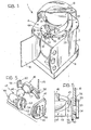
- the reference 1 ( Figures 1 and 2) denotes, as a whole, a winding reel for a motor vehicle seat belt, comprising a support body 2, a shaft. 3 which rotates in this support body and means serving to block the rotation of this shaft 3 these means being designated as a whole by reference 4.
- the support body 2 is constituted by a base plate 5, in which are made three holes 6 used for its attachment to the body of the motor vehicle and by two plates 7 and 8 fixed perpendicularly to the opposite ends of this base plate 5.
- Each of the plates 7 and 8 has, in its center, a circular hole 9, provided internally with a plastic sleeve 10, crossed by one end of the shaft 3.
- each of the plates 7 and 8 is provided with a pair of tapped holes 11 intended to receive screws 12 for fixing a side cover 13.
- the plate 7 comprises two series of tapped holes 14, concentric with the axis of rotation of the shaft 3, these holes being separated from each other by a series of holes 15 of larger diameter, which are also concentric with the axis of rotation of the shaft 3.
- This shaft 3 as shown in detail in FIG. 3, has a central part 16 in which a longitudinal notch 17 is made which serves to fasten one end of a seat belt 16.
- the reference 19 designates an end of reduced diameter of the shaft 3, which passes through the circular hole 9 of the plate 8 and which extends to the outside of the support body 2. This end 19 is connected to a spring helical (not shown) which allows the automatic rewinding of the seat belt on the shaft 3.
- the reference 20 designates the opposite end of the shaft 3 which passes through the circular hole 9 made in the plate 7 and which extends in overhang outside the support body 2.
- the end 20 comprises a part 21 of larger diameter, adjacent to the plate 7, in which there is a peripheral crown of four front teeth 22.
- These front teeth are distributed angularly in a regular manner and they are separated by as many inclined surfaces 23, which go from the base of each of the teeth 22 to about halfway up the next tooth 22.
- the reference 24 designates an end portion, of smaller diameter of the end 20, extending outward from the top of the front teeth 22.
- the reference 25 designates a toothed wheel crossed, in its center, by the end part 24 of the end. 20 of the shaft 3.
- This wheel 25 has, on its face facing outwards, a crown of front teeth 26 forming a saw profile, while on its opposite face is a peripheral crown of four front teeth 27, evenly distributed angularly.
- the front teeth 27 engage in the voids between the front teeth 22 of the end 20 of the shaft 3 and they are smaller than the corresponding vacuum.
- the wheel 25 can move longitudinally relative. port to the tree, between a rest position, at which the flanks of the teeth 27 are applied against the flanks of the teeth 22 at the base of the inclined surfaces 23 and a position, resulting from an angular displacement between the wheel 25 and the shaft 3, to which the flanks of the teeth 27 are applied against the flanks of the teeth 22, at the top of the inclined surfaces 23.
- the toothed wheel 25 has an annular peripheral groove 29 formed on its external surface in a part 28 between the teeth 26 and the front teeth 27.
- the reference 30 designates an elastically expandable ring, housed inside this annular groove 29.
- the reference 31 designates a ring mounted so as to be able to rotate with friction on the toothed wheel 25 and externally provided with a radial toothing 32 with a saw profile.
- the toothed ring 31 is provided with an annular groove 33 formed in its internal surface, intended to receive the expandable elastic ring 30 housed in the annular groove 29.
- the reference 34 designates a cover fixed on the plate 7 of the support body 2 and coaxial with the shaft 3.
- the cover 34 as shown in detail in FIG. 4, comprises a semi-cylindrical side wall 35, closed, at one end, by a bottom 36 which internally has four front teeth d stop 62, distributed regularly in a regular manner and directed towards the support body 2.
- This semi-cylindrical wall 35 comprises, along a part of its free end edge, a radial flange 37 serving, for fixing the support body.
- This flange 37 is provided with two end holes 38, diametrically opposite and directed longitudinally, serving for the passage of two screws 39 and a cylindrical appendage 40 directed longitudinally, facing the support body 2.
- the reference 41 designates a flat appendage which leaves tangentially from a free end of the side wall 35.
- This appendage 41 penetrates, in the vicinity of its free end, a hole 42 of elongated shape, directed transversely and having a central part 43 of circular profile.
- a support 44 which carries the articulation pivot 45 of a pawl 46.
- This support 44 is obtained by stamping a plastic material, as shown in detail in FIGS. 5 and 6, and it comprises an emerical cup 47 containing a metal ball 48 and connected, by means of an external rib 49, to a cylindrical rod 50 traversed, in its upper part, by a hole 51 oriented parallel to the edge of this bowl 47.
- This cylindrical rod 50 is connected, at its free end, to a transverse stop collar 52, of diameter greater than that of the circular seat 42 and to an elastic strip 53, this collar 52 and this strip 53 being parallel to one another and separated by a cylindrical part 54.
- the elastic strip 53 is rectangular in shape and its small sides are rounded; it has on its internal face a series of projections or bosses 55.
- this elastic strip 53 passes through the hole 42 and it is oriented in such a way that the projections 55 can be engaged at will with a sharp blow in a series of seats 56 concentric with the hole 42 practiced in flat appendix 41.
- the pawl 46 comprises a hemispherical central cup 57 situated opposite the hemispherical cup 47 of the support 44 and connected along its outer edge, to a small fork 58 which carries the articulation pivot 45.
- the reference 59 designates an appendage connected in overhang to the outer edge of the hemispherical bowl 57 by the part opposite to the fork 56.
- This appendage 59 has a rounded end edge 60 which engages with the radial toothing of stop 32 of the toothed ring 31.
- the support 44 can be fixed to the flat appendage 41 of the cover 34, so that the orientation of the pivot pin 45 of the pawl 46 can be varied around an axis perpendicular to the axis of the shaft 3, from a central position at which this pivot 45 is parallel to the axis of the shaft 3, as shown in Figure 1.
- the reference 61 designates, finally, a helical spring which reacts elastically between the cover 34 and the toothed wheel 25, when there is a longitudinal displacement of this toothed hole 25 relative to the shaft 3.
- the axis of rotation of the shaft 3 is oriented in the direction of the longitudinal axis of the vehicle 1
- the cover 34 is fixed to the support body 2 so as to maintain the pawl in a horizontal position, parallel to the transverse axis of the motor vehicle, and the support 44 is fixed to the flat appendage 41 in a position such that it orients the articulation pivot 45 parallel to the longitudinal axis of the motor vehicle.
- the toothed wheel 25, the toothed ring 31, the front stop teeth 62 and the pawl 46 constitute the means 4 serving to block the rotation of the shaft 3 and operate as follows.
- the toothed wheel 25 When the shaft 3 undergoes a sudden angular acceleration, for example under the effect of a brutal traction on the belt 18, due to an impact at the front of the vehicle, the toothed wheel 25, due to the inertia, performs an angular displacement smaller than that of the shaft 3.
- the sides of the teeth 27 of the toothed wheel 25 come apply against the sides of the teeth 22 at the top of the inclined surfaces 23, which firmly stops the rotation of the shaft 3.
- the ball 48 moves by inertia inside the seat 47 of the support 44 and it causes, by abutting against the inner wall of the seat 57, the rotation from the pawl 46 upwards around the articulation pivot 45. Under the effect of this rotation, the extreme edge 60 of the pawl 46 engages with the radial stop toothing 32 of the toothed ring 31.
- the toothed ring 31 is mounted so that it can rotate with friction on the toothed wheel 25, it also occurs in this case, by inertia effect, a longitudinal displacement of this toothed wheel 25 relative to the shaft 3, which causes engagement, in the crown of front teeth 26,. of the front stop teeth 62.
- the relative rotation of the toothed ring 31 and the toothed wheel 25 allows the teeth 26 to engage in a seat comprised between two successive teeth 62, which prevents shocks and guarantees a safe blocking of shaft rotation 3.
- the winding reel according to the invention is very safe to operate, that it is of a relatively simple and inexpensive construction and further that it can be adapted quickly at various mounting positions.
Landscapes
- Engineering & Computer Science (AREA)
- Mechanical Engineering (AREA)
- Automotive Seat Belt Assembly (AREA)
- Transmission Devices (AREA)
Applications Claiming Priority (2)
| Application Number | Priority Date | Filing Date | Title |
|---|---|---|---|
| CH128483A CH652978A5 (fr) | 1983-03-10 | 1983-03-10 | Bobine d'enroulement pour une ceinture de securite de vehicule automobile. |
| CH1284/83 | 1983-03-10 |
Publications (2)
| Publication Number | Publication Date |
|---|---|
| EP0118650A2 true EP0118650A2 (de) | 1984-09-19 |
| EP0118650A3 EP0118650A3 (de) | 1986-09-03 |
Family
ID=4206826
Family Applications (1)
| Application Number | Title | Priority Date | Filing Date |
|---|---|---|---|
| EP83810136A Withdrawn EP0118650A3 (de) | 1983-03-10 | 1983-04-07 | Aufroller für Kraftfahrzeug-Sicherheitsgurte |
Country Status (2)
| Country | Link |
|---|---|
| EP (1) | EP0118650A3 (de) |
| CH (1) | CH652978A5 (de) |
Cited By (2)
| Publication number | Priority date | Publication date | Assignee | Title |
|---|---|---|---|---|
| EP0669233A3 (de) * | 1994-02-09 | 1996-11-27 | Trw Vehicle Safety Systems | Sicherheitsgurtaufroller. |
| EP1010593A3 (de) * | 1998-12-18 | 2003-09-03 | TRW Occupant Restraint Systems GmbH & Co. KG | Sensor für einen Gurtaufroller |
Family Cites Families (1)
| Publication number | Priority date | Publication date | Assignee | Title |
|---|---|---|---|---|
| IT1091369B (it) * | 1977-12-02 | 1985-07-06 | Scudo Soc S R L | Arrotolatore per cinture di sicurezza per autoveicoli |
-
1983
- 1983-03-10 CH CH128483A patent/CH652978A5/fr not_active IP Right Cessation
- 1983-04-07 EP EP83810136A patent/EP0118650A3/de not_active Withdrawn
Cited By (2)
| Publication number | Priority date | Publication date | Assignee | Title |
|---|---|---|---|---|
| EP0669233A3 (de) * | 1994-02-09 | 1996-11-27 | Trw Vehicle Safety Systems | Sicherheitsgurtaufroller. |
| EP1010593A3 (de) * | 1998-12-18 | 2003-09-03 | TRW Occupant Restraint Systems GmbH & Co. KG | Sensor für einen Gurtaufroller |
Also Published As
| Publication number | Publication date |
|---|---|
| EP0118650A3 (de) | 1986-09-03 |
| CH652978A5 (fr) | 1985-12-13 |
Similar Documents
| Publication | Publication Date | Title |
|---|---|---|
| FR2820375A1 (fr) | Dispositif de fixation pour accoudoir amovible et dispositif d'assise comportant un tel dispositif de fixation | |
| FR2849089A1 (fr) | Appareil a verrou de couvercle de boite a gants | |
| FR2721060A1 (fr) | Loquet à levier avec patte ayant une action d'éjection. | |
| EP4385369B1 (de) | Faltbares kindertransat | |
| FR2515049A1 (fr) | Enrouleur pour ceinture de securite perfectionne | |
| EP0479673B1 (de) | Getriebemotor mit seinem Gehäuseverschlussdeckel, insbesondere für eine Scheibenwischeranlage | |
| FR2611355A1 (fr) | Mecanisme de ressort pour charnieres de pare-soleil de vehicules automobiles et pare-soleil muni de ce mecanisme | |
| EP0367665B1 (de) | Handvorrichtung zur Verstellung eines Sicherheitsgurtels | |
| EP0118650A2 (de) | Aufroller für Kraftfahrzeug-Sicherheitsgurte | |
| EP0808783B1 (de) | Anlage mit beweglichen Klinken mit Rückstell-Unterstützung zum Lagern in allen Stellungen, insbesondere für im wesentlichen flache Gegenstände mit relativ grossen Abmessungen | |
| FR2467115A1 (fr) | Dispositif d'arrimage d'objets divers, notamment sacs et valises dans un coffre de vehicule | |
| EP0195694B1 (de) | Sicherheitsgurtroller mit walzenförmigem Körper | |
| FR2690887A1 (fr) | Rétroviseur pour un véhicule équipé d'un type perfectionné de dispositif de support et d'orientation pour une plaque réfléchissante. | |
| FR2504396A1 (fr) | Enrouleur a blocage automatique pour ceinture de securite | |
| EP0085586A1 (de) | Schlossbedienung mit Druckknopf | |
| EP0078204B1 (de) | Selbstsperrender Aufwickelautomat für Sicherheitsgurte | |
| FR2806052A1 (fr) | Dispositif de deviation d'une sangle de ceinture de securite en sortie d'un enrouleur pour passager arriere de vehicule automobile | |
| FR2749618A1 (fr) | Dispositif de montage pour le positionnement et le maintien de deux pieces l'une par rapport a l'autre | |
| FR2706409A1 (fr) | Dispositif d'accrochage réversible d'un siège sur un plancher de véhicule automobile. | |
| EP0108018B1 (de) | Sperrvorrichtung für Sicherheitsgurtaufroller | |
| FR2758298A1 (fr) | Porte-gobelets, particulierement pour vehicule automobile | |
| EP0077494B1 (de) | Gurtaufrollautomat für Sicherheitsgurtsystem | |
| FR3000010A1 (fr) | Ensemble de fixation de roue de secours dans un vehicule automobile | |
| FR2594391A1 (fr) | Retroviseur exterieur pour vehicule, comprenant des moyens d'assemblage simplifies de son articulation | |
| EP0146467A2 (de) | Befestigung einer Fahrzeugantenne |
Legal Events
| Date | Code | Title | Description |
|---|---|---|---|
| PUAI | Public reference made under article 153(3) epc to a published international application that has entered the european phase |
Free format text: ORIGINAL CODE: 0009012 |
|
| AK | Designated contracting states |
Designated state(s): AT BE DE FR GB IT LU NL SE |
|
| PUAL | Search report despatched |
Free format text: ORIGINAL CODE: 0009013 |
|
| AK | Designated contracting states |
Kind code of ref document: A3 Designated state(s): AT BE DE FR GB IT LU NL SE |
|
| 17P | Request for examination filed |
Effective date: 19860909 |
|
| STAA | Information on the status of an ep patent application or granted ep patent |
Free format text: STATUS: THE APPLICATION HAS BEEN WITHDRAWN |
|
| 17Q | First examination report despatched |
Effective date: 19870408 |
|
| 18W | Application withdrawn |
Withdrawal date: 19870427 |
|
| RIN1 | Information on inventor provided before grant (corrected) |
Inventor name: SEILER, MARTIN |