EP0118655A2 - Procédé pour réaliser des processus métallurgiques ou chimiques et bas-fourneau - Google Patents
Procédé pour réaliser des processus métallurgiques ou chimiques et bas-fourneau Download PDFInfo
- Publication number
- EP0118655A2 EP0118655A2 EP83890225A EP83890225A EP0118655A2 EP 0118655 A2 EP0118655 A2 EP 0118655A2 EP 83890225 A EP83890225 A EP 83890225A EP 83890225 A EP83890225 A EP 83890225A EP 0118655 A2 EP0118655 A2 EP 0118655A2
- Authority
- EP
- European Patent Office
- Prior art keywords
- furnace
- charge
- plasma torch
- electrode
- shaft furnace
- Prior art date
- Legal status (The legal status is an assumption and is not a legal conclusion. Google has not performed a legal analysis and makes no representation as to the accuracy of the status listed.)
- Granted
Links
- 238000000034 method Methods 0.000 title claims abstract description 35
- 238000010310 metallurgical process Methods 0.000 title claims description 8
- 238000001311 chemical methods and process Methods 0.000 title claims description 7
- 239000000463 material Substances 0.000 claims abstract description 42
- 230000001681 protective effect Effects 0.000 claims abstract description 14
- 239000007787 solid Substances 0.000 claims abstract description 10
- XLYOFNOQVPJJNP-UHFFFAOYSA-N water Substances O XLYOFNOQVPJJNP-UHFFFAOYSA-N 0.000 claims abstract description 6
- 238000001816 cooling Methods 0.000 claims abstract description 5
- 239000011819 refractory material Substances 0.000 claims abstract description 5
- 238000004519 manufacturing process Methods 0.000 claims description 13
- 229910052799 carbon Inorganic materials 0.000 claims description 12
- 239000003245 coal Substances 0.000 claims description 11
- XEEYBQQBJWHFJM-UHFFFAOYSA-N Iron Chemical compound [Fe] XEEYBQQBJWHFJM-UHFFFAOYSA-N 0.000 claims description 10
- 239000000203 mixture Substances 0.000 claims description 9
- 239000005997 Calcium carbide Substances 0.000 claims description 8
- OKTJSMMVPCPJKN-UHFFFAOYSA-N Carbon Chemical compound [C] OKTJSMMVPCPJKN-UHFFFAOYSA-N 0.000 claims description 8
- CLZWAWBPWVRRGI-UHFFFAOYSA-N tert-butyl 2-[2-[2-[2-[bis[2-[(2-methylpropan-2-yl)oxy]-2-oxoethyl]amino]-5-bromophenoxy]ethoxy]-4-methyl-n-[2-[(2-methylpropan-2-yl)oxy]-2-oxoethyl]anilino]acetate Chemical compound CC1=CC=C(N(CC(=O)OC(C)(C)C)CC(=O)OC(C)(C)C)C(OCCOC=2C(=CC=C(Br)C=2)N(CC(=O)OC(C)(C)C)CC(=O)OC(C)(C)C)=C1 CLZWAWBPWVRRGI-UHFFFAOYSA-N 0.000 claims description 8
- 229910052742 iron Inorganic materials 0.000 claims description 6
- 229910001021 Ferroalloy Inorganic materials 0.000 claims description 5
- 239000000571 coke Substances 0.000 claims description 5
- 230000000149 penetrating effect Effects 0.000 claims description 5
- 239000000155 melt Substances 0.000 claims description 3
- 238000005275 alloying Methods 0.000 claims description 2
- 239000010419 fine particle Substances 0.000 claims description 2
- 230000008018 melting Effects 0.000 abstract description 10
- 238000002844 melting Methods 0.000 abstract description 9
- 238000006243 chemical reaction Methods 0.000 abstract description 5
- 230000002829 reductive effect Effects 0.000 abstract description 5
- 230000005855 radiation Effects 0.000 abstract description 4
- 229910052804 chromium Inorganic materials 0.000 description 11
- 229910052750 molybdenum Inorganic materials 0.000 description 11
- 229910052758 niobium Inorganic materials 0.000 description 11
- ODINCKMPIJJUCX-UHFFFAOYSA-N Calcium oxide Chemical compound [Ca]=O ODINCKMPIJJUCX-UHFFFAOYSA-N 0.000 description 10
- 229910052748 manganese Inorganic materials 0.000 description 10
- 239000002245 particle Substances 0.000 description 9
- 239000007789 gas Substances 0.000 description 7
- 229910052759 nickel Inorganic materials 0.000 description 7
- XKRFYHLGVUSROY-UHFFFAOYSA-N Argon Chemical compound [Ar] XKRFYHLGVUSROY-UHFFFAOYSA-N 0.000 description 6
- 235000012255 calcium oxide Nutrition 0.000 description 5
- 239000000292 calcium oxide Substances 0.000 description 5
- 229910000604 Ferrochrome Inorganic materials 0.000 description 4
- 229910000831 Steel Inorganic materials 0.000 description 4
- 229910052786 argon Inorganic materials 0.000 description 4
- 229910052802 copper Inorganic materials 0.000 description 4
- 229910002804 graphite Inorganic materials 0.000 description 4
- 239000010439 graphite Substances 0.000 description 4
- 238000010438 heat treatment Methods 0.000 description 4
- 229910052751 metal Inorganic materials 0.000 description 4
- 239000002184 metal Substances 0.000 description 4
- 229910052710 silicon Inorganic materials 0.000 description 4
- 239000010959 steel Substances 0.000 description 4
- 229910000616 Ferromanganese Inorganic materials 0.000 description 3
- DALUDRGQOYMVLD-UHFFFAOYSA-N iron manganese Chemical compound [Mn].[Fe] DALUDRGQOYMVLD-UHFFFAOYSA-N 0.000 description 3
- 238000010309 melting process Methods 0.000 description 3
- 238000011946 reduction process Methods 0.000 description 3
- 229910045601 alloy Inorganic materials 0.000 description 2
- 239000000956 alloy Substances 0.000 description 2
- 229910000851 Alloy steel Inorganic materials 0.000 description 1
- UGFAIRIUMAVXCW-UHFFFAOYSA-N Carbon monoxide Chemical compound [O+]#[C-] UGFAIRIUMAVXCW-UHFFFAOYSA-N 0.000 description 1
- 229910000805 Pig iron Inorganic materials 0.000 description 1
- 230000015572 biosynthetic process Effects 0.000 description 1
- 239000011449 brick Substances 0.000 description 1
- OSMSIOKMMFKNIL-UHFFFAOYSA-N calcium;silicon Chemical compound [Ca]=[Si] OSMSIOKMMFKNIL-UHFFFAOYSA-N 0.000 description 1
- 229910002091 carbon monoxide Inorganic materials 0.000 description 1
- 239000012159 carrier gas Substances 0.000 description 1
- 239000000498 cooling water Substances 0.000 description 1
- 238000009826 distribution Methods 0.000 description 1
- 230000003628 erosive effect Effects 0.000 description 1
- 239000007770 graphite material Substances 0.000 description 1
- 239000011261 inert gas Substances 0.000 description 1
- 230000000977 initiatory effect Effects 0.000 description 1
- 239000007788 liquid Substances 0.000 description 1
- 239000012768 molten material Substances 0.000 description 1
- 239000008188 pellet Substances 0.000 description 1
- 238000002360 preparation method Methods 0.000 description 1
- 239000004576 sand Substances 0.000 description 1
- 125000006850 spacer group Chemical group 0.000 description 1
- 239000002436 steel type Substances 0.000 description 1
- 239000000126 substance Substances 0.000 description 1
- 230000008646 thermal stress Effects 0.000 description 1
Images


Classifications
-
- C—CHEMISTRY; METALLURGY
- C21—METALLURGY OF IRON
- C21B—MANUFACTURE OF IRON OR STEEL
- C21B13/00—Making spongy iron or liquid steel, by direct processes
- C21B13/12—Making spongy iron or liquid steel, by direct processes in electric furnaces
- C21B13/125—By using plasma
-
- C—CHEMISTRY; METALLURGY
- C22—METALLURGY; FERROUS OR NON-FERROUS ALLOYS; TREATMENT OF ALLOYS OR NON-FERROUS METALS
- C22B—PRODUCTION AND REFINING OF METALS; PRETREATMENT OF RAW MATERIALS
- C22B4/00—Electrothermal treatment of ores or metallurgical products for obtaining metals or alloys
- C22B4/005—Electrothermal treatment of ores or metallurgical products for obtaining metals or alloys using plasma jets
-
- H—ELECTRICITY
- H05—ELECTRIC TECHNIQUES NOT OTHERWISE PROVIDED FOR
- H05B—ELECTRIC HEATING; ELECTRIC LIGHT SOURCES NOT OTHERWISE PROVIDED FOR; CIRCUIT ARRANGEMENTS FOR ELECTRIC LIGHT SOURCES, IN GENERAL
- H05B7/00—Heating by electric discharge
-
- Y—GENERAL TAGGING OF NEW TECHNOLOGICAL DEVELOPMENTS; GENERAL TAGGING OF CROSS-SECTIONAL TECHNOLOGIES SPANNING OVER SEVERAL SECTIONS OF THE IPC; TECHNICAL SUBJECTS COVERED BY FORMER USPC CROSS-REFERENCE ART COLLECTIONS [XRACs] AND DIGESTS
- Y02—TECHNOLOGIES OR APPLICATIONS FOR MITIGATION OR ADAPTATION AGAINST CLIMATE CHANGE
- Y02P—CLIMATE CHANGE MITIGATION TECHNOLOGIES IN THE PRODUCTION OR PROCESSING OF GOODS
- Y02P10/00—Technologies related to metal processing
- Y02P10/10—Reduction of greenhouse gas [GHG] emissions
- Y02P10/134—Reduction of greenhouse gas [GHG] emissions by avoiding CO2, e.g. using hydrogen
Definitions
- the invention relates to a method for carrying out metallurgical or chemical processes in a shaft furnace with the supply of electrical energy by means of a plasma burner device which penetrates the top cover of the shaft furnace.
- US Pat. No. 3,404,078 discloses a method for producing a plasma arc, one of the electrodes consisting of a fluidized bed of electrically conductive particles. Various materials can be introduced into the plasma area; the products resulting in the high temperature zone reach the fluidized bed and are cooled there. The process according to US-PS is therefore not suitable for obtaining products in molten form.
- the invention aims to overcome the difficulties outlined and set itself the task of both for the implementation of metallurgical processes as well as to create a process suitable for chemical high-temperature reactions, in which a rapid melting and a rapid reaction between the charge material components is achieved and in which the progress of the process is controlled in an improved manner; can be.
- This object is achieved according to the invention in a method of the type described in the introduction in that a plasma torch is formed between a centrally arranged electrode which penetrates the top cover of the shaft furnace and a counterelectrode which penetrates the bottom of the shaft furnace, and that the charge material is introduced concentrically around the torch , wherein a protective wall of solid charge material components is stacked on the inner wall of the furnace and the charge material reaches the area of the plasma torch from the inside of the protective wall.
- a particular advantage of the procedure according to the invention is further that more energy is absorbed by the charge material which surrounds the flare area in the manner of a curtain than in conventional processes, as a result of which the speed of the metallurgical or chemical processes is significantly accelerated.
- the particles of the charging material falling down in the form of a curtain or the charging material stacked concentrically around the flare area in the lower region of the furnace absorb the heat radiation for the most part and are preheated thereby, so that an optimal use is made of the electrical current Gives energy.
- the method according to the invention can advantageously be used, for example, for the production of ferroalloys, calcium silicon, pig iron, furthermore for the structural melting of high-alloy steel types and for the remelting of the type of scrap.
- it is also excellently suited for carrying out chemical processes that take place at high temperatures, such as the production of calcium carbide.
- the process according to the invention is also distinguished by a high degree of alloy element output compared to conventional melting processes, such as arc melting.
- a small amount of the charging material can be introduced into the area of the counterelectrode and, after the plasma torch is ignited, further charging material can be introduced continuously. If the layer is too high, the still solid charge would hinder the formation of the plasma torch, but it has sufficient electrical conductivity to enable the plasma torch to be ignited in a small amount.
- the charge material is expediently introduced continuously through a ring of charging tubes surrounding the electrode or through an annular charging slot surrounding the electrode.
- a ring of charging tubes surrounding the electrode For example, 6 to 12 charging tubes can be provided.
- Batch goods with a grain size of up to 25 mm are preferably used. Grain sizes of up to 10 mm are particularly preferred for lumpy goods and those of 5 to 15 mm when pellets are used. All gases which are usually used for this purpose, such as Ar, He, H 2 , N 2 and CO, are suitable as plasma gases.
- Yaw openings can also be used to feed finely divided components of the charge through internal channels of the electrode.
- ferro alloys For the production of ferro alloys from oxidic ores and carbon-containing material, a mixture of the corresponding ores, in which the alloying elements and the iron are predominantly in oxidic form, and of coal or coke is used as the charge material.
- feedstocks with different grain sizes, even dusty feedstocks, can be melted and reacted without problems in these reductive processes, whereas so far - especially in the production of CaC 2 by resistance heating described above - only. coarse input materials could be used.
- the invention further comprises a downhole furnace for carrying out the method according to the invention - in particular for carrying out reductive processes such as the production of ferro alloys and calcium carbide.
- the furnace has a refractory-lined furnace body and a guide for the plasma torch device which is inserted into the furnace body, an annular space for supplying the charge or charge being provided between the guide and the refractory lining.
- an upper cover can be placed gas-tight on the furnace body, which has an inwardly projecting column made of refractory material, that the column has a central bore for the passage of an electrode and a water cooling system, and a counter electrode is provided in the bottom of the shaft furnace is, in order to form the plasma torch a truncated cone-shaped space between the mouth of the electrode (the plasma torch), the bottom electrode and the inside of the protective wall is made of solid charge material components.
- the walls of the shaft receiving the cargo are advantageously designed to diverge towards the bottom.
- the electrode of the plasma torch device which is led through the central bore of the column made of refractory material, has internal channels for supplying fine-particle charge material components, in particular coal.
- FIG. 1 shows a vertical section through a downhole furnace and Fig. 2 is a plan view from above.
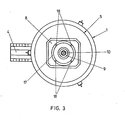
- Fig. 3 shows a plan view of the furnace with a different design of the charging opening.
- FIG. 4 shows a modified embodiment of a downhole furnace, which is particularly suitable for carrying out the reductive processes mentioned.
- Fig. 1 denotes the casing of the shaft furnace, which has a lining made of refractory bricks 2.
- the bottom of the shaft furnace is built from graphite material 3 and in the bottom is a side A usg electrinne 4 is provided.
- An upper cover 5 rests on the shaft furnace, which gas-tightly seals the interior of the furnace by means of a cover sword 6 which engages in a sand cup 7 running all around.
- the core 8 of the cover which is provided with water cooling, has a number of bores, etc. a central water-cooled bore 9, through which the plasma torch or electrode 10 is guided, and a ring of six further bores 11 surrounding the central bore, through which charging tubes 12 are guided for introducing the charging material or the Möller components.
- the counter electrode 13 is arranged in the bottom of the shaft furnace, opposite the mouth of the plasma torch 10.
- a small amount of charge is introduced through the charge tubes 12; then the discharge is ignited, forming a free-burning plasma torch 14, and a sump 15 is generated from the melted charge, thereby initiating the process. Then further charge material is continuously introduced, with a protective wall 16 of solid charge material components being stacked around the sump 15 on the inner wall 2 of the furnace, which protective wall 16 protects the refractory lining from excessive temperatures and which is preheated at the same time by the radiant heat of the plasma torch 14.
- Fig. 3 the furnace jacket is again designated 1, an upper cover 5 is placed gas-tight on the furnace body. Furthermore, the pouring spout 4 leading laterally away from the base part of the furnace is visible.
- a central bore 9 is provided, through the latter a plasma torch 10 is guided.
- An annular charging slot 17 concentrically surrounds the bore 9. In the charging slot 17, four spacers 18 are provided, which also contain channels for the cooling water.
- the particles of the charge material form a tight curtain around the area of the plasma torch which burns between the electrode in the burner 10 and the counter electrode 13 passing through the bottom of the shaft furnace.
- the particle curtain protects the furnace lining from thermal stress and absorbs most of the thermal energy radiated by the plasma torch, so that a considerable amount of the cargo reaches the bottom of the shaft furnace or the melt sump already in a liquid state.
- the larger, not yet melted particles of the charge material contribute to the layering of the protective wall 16.
- the casing of the vessel is again designated 1 and the refractory lining is designated 2.
- the bottom of the furnace is formed from graphite tamping mass 3, which bottom has a lateral drainage channel or pouring channel 4 for molten material.
- a water-cooled upper cover 19 is placed, which cover has a columnar guide 20 towards the inside of the furnace, which consists of refractory material.
- the frustoconical column has a central bore 21 which has a water cooling 22. Through the bore, the plasma torch 10 is guided, with its mouth 23 the lower end of the Towering over pillar 20.
- annular, downwardly diverging space 24 is formed, in which solid cargo or Möller components with the function of a protective wall 16 are stored, through which the cover 19 penetrating feed chute 25 having metering flaps can be introduced.
- an exhaust pipe for the gas released in a reduction process is designated.
- a frustoconical space 27 which converges downward, remains free between the bottom electrode 13 and the mouth 23 of the plasma torch or the electrode 10.
- the plasma torch 14 is ignited at the beginning of the process after a small amount of charge or Möller has been introduced; then the annular space 24 is filled with Möller components by just adding the Möller to just below the exhaust pipe 26.
- Möller components are continuously melted and converted in the recessed space 27; the resulting gas, in particular CO, rises through the layer of furniture or the protective wall 16 and causes preheating and pre-reduction.
- finely divided coal can additionally be introduced into the space 27 through one or more internal channels of the plasma torch during the process, with additional CO being formed.
- Example 1 Production of ferromanganese: 1300 kg of ferromanganese ores (with 45 to 55% Mn, up to 10% Fe, where Mn and Fe are predominantly in the form of oxides) - mixed with 400 to 500 kg of coal, coke or coal grit - are continuously mixed with charged at a speed of about 1.5-3 kg / s. About 1 t of ferromanganese with 75% Mn, 2% oxides, the rest iron, is applied after about 10 to 20 minutes.
- the furnace size is limited by the highest possible burner output;
- Such an oven with a conventional burner enables an output of about 5 t of product / h.
- the output is 8458 kg steel of the composition: 0.041% C, 0.35% Si, 1.27% Mn, 0.016% P, 0.01% S, 18.57% Cr, 10.95% Ni, 2.29 % Mo, 0.11% Cu, 0.63% Nb.
- the total metal burn-up is 3%, the degree of application on the respective alloy elements is therefore: 99% Ni, 99% Cr, 99% Mo, 99% Mn, 100% Nb.
- a Möller mix of 3000 kg of burnt lime and 195 0 kg of coal with discontinuous grain size distribution up to a maximum of 25 mm was continuously introduced into a shaft furnace of the embodiment shown in FIG. 4 at a charging rate of 3 kg / s after initially a small amount of Möller in the range of counter electrode penetrating the bottom of the shaft furnace and the plasma torch was ignited. Argon was used as the plasma gas.
- the calcium carbide applied had a purity of 90.2%.
Landscapes
- Engineering & Computer Science (AREA)
- Chemical & Material Sciences (AREA)
- Plasma & Fusion (AREA)
- Physics & Mathematics (AREA)
- Metallurgy (AREA)
- Manufacturing & Machinery (AREA)
- Organic Chemistry (AREA)
- Materials Engineering (AREA)
- Mechanical Engineering (AREA)
- Environmental & Geological Engineering (AREA)
- Geology (AREA)
- General Life Sciences & Earth Sciences (AREA)
- Life Sciences & Earth Sciences (AREA)
- Geochemistry & Mineralogy (AREA)
- Vertical, Hearth, Or Arc Furnaces (AREA)
- Furnace Details (AREA)
- Organic Low-Molecular-Weight Compounds And Preparation Thereof (AREA)
- Acyclic And Carbocyclic Compounds In Medicinal Compositions (AREA)
- Pharmaceuticals Containing Other Organic And Inorganic Compounds (AREA)
Applications Claiming Priority (4)
| Application Number | Priority Date | Filing Date | Title |
|---|---|---|---|
| AT4638/82 | 1982-12-22 | ||
| AT0463882A AT382355B (de) | 1982-12-22 | 1982-12-22 | Verfahren zur herstellung von calciumcarbid und schachtofen zur durchfuehrung des verfahrens |
| AT383383A AT386008B (de) | 1983-10-28 | 1983-10-28 | Verfahren zur durchfuehrung von metallurgischen prozessen |
| AT3833/83 | 1983-10-28 |
Publications (3)
| Publication Number | Publication Date |
|---|---|
| EP0118655A2 true EP0118655A2 (fr) | 1984-09-19 |
| EP0118655A3 EP0118655A3 (en) | 1985-04-17 |
| EP0118655B1 EP0118655B1 (fr) | 1988-03-02 |
Family
ID=25600499
Family Applications (1)
| Application Number | Title | Priority Date | Filing Date |
|---|---|---|---|
| EP83890225A Expired EP0118655B1 (fr) | 1982-12-22 | 1983-12-15 | Procédé pour réaliser des processus métallurgiques ou chimiques et bas-fourneau |
Country Status (9)
| Country | Link |
|---|---|
| US (1) | US4518419A (fr) |
| EP (1) | EP0118655B1 (fr) |
| AU (1) | AU563376B2 (fr) |
| CA (1) | CA1213928A (fr) |
| DD (1) | DD215803A5 (fr) |
| DE (1) | DE3375805D1 (fr) |
| ES (1) | ES528272A0 (fr) |
| NO (1) | NO163714C (fr) |
| PT (1) | PT77841B (fr) |
Cited By (4)
| Publication number | Priority date | Publication date | Assignee | Title |
|---|---|---|---|---|
| EP0171385A1 (fr) * | 1984-08-03 | 1986-02-12 | VOEST-ALPINE Aktiengesellschaft | Procédé pour la préparation de carbure de calcium et four à cuve pour la mise en oeuvre de ce procédé |
| EP0292469A1 (fr) * | 1987-05-18 | 1988-11-23 | K.H.T. Know-How-Trading Patentverwertung Gesellschaft m.b.H. | Procédé et dispositif pour opérations chimiques à haute température |
| WO2007134789A3 (fr) * | 2006-05-18 | 2008-04-24 | Alzchem Hart Gmbh | Utilisation de résidus et/ou de déchets dans des fours électriques à cuve basse |
| EP2487265A4 (fr) * | 2009-10-08 | 2016-01-13 | Kobe Steel Ltd | Dispositif de production de métal fondu |
Families Citing this family (5)
| Publication number | Priority date | Publication date | Assignee | Title |
|---|---|---|---|---|
| SE451756B (sv) * | 1984-10-19 | 1987-10-26 | Skf Steel Eng Ab | Plasmageneratorinstallation i schaktugn |
| AT386717B (de) * | 1986-12-01 | 1988-10-10 | Voest Alpine Ag | Verfahren zum zuenden eines plasmabogens |
| US4765828A (en) * | 1987-06-19 | 1988-08-23 | Minnesota Power & Light Company | Method and apparatus for reduction of metal oxides |
| GB9315205D0 (en) † | 1993-07-22 | 1993-09-08 | Exxon Chemical Patents Inc | Additives and fuel compositions |
| JP5330185B2 (ja) | 2009-10-08 | 2013-10-30 | 株式会社神戸製鋼所 | 溶融金属製造装置 |
Family Cites Families (11)
| Publication number | Priority date | Publication date | Assignee | Title |
|---|---|---|---|---|
| AT257964B (de) * | 1963-10-01 | 1967-11-10 | Union Carbide Corp | Verfahren zur Reduktion von Metalloxyden |
| DE1252336B (de) * | 1964-08-13 | 1967-10-19 | The Battelle Development Corporation, Columbus, Ohio (V St A) | Lichtbogenplasmabrenner und Verfahren zum Betrieb eines solchen Brenners |
| US3380904A (en) * | 1965-04-20 | 1968-04-30 | Dev Corp | Confining the reaction zone in a plasma arc by solidifying a confining shell around the zone |
| DE1433351A1 (de) * | 1967-04-19 | 1968-11-28 | Rlieinstahl Exp U Industrieanl | OElschmelzofen fuer die Verhuettung von Eisenerzen |
| DE2110274C2 (de) * | 1971-03-04 | 1973-01-04 | Fried. Krupp Gmbh, 4300 Essen | Vorrichtung zum Einschmelzen von Metallschwamm durch inerte Gasplasmen |
| US3736358A (en) * | 1971-07-30 | 1973-05-29 | Westinghouse Electric Corp | Process for iron ore reduction and electric furnace for iron ore reduction having at least one nonconsumable electrode |
| US3917479A (en) * | 1971-12-03 | 1975-11-04 | Nat Res Dev | Furnaces |
| SE360679C (fr) * | 1972-02-24 | 1975-08-18 | Allamanna Svenska Elektriska Ab | |
| US3834895A (en) * | 1973-04-11 | 1974-09-10 | Park Ohio Industries Inc | Method of reclaiming iron from ferrous dust |
| GB1565065A (en) * | 1976-08-23 | 1980-04-16 | Tetronics Res & Dev Co Ltd | Carbothermal production of aluminium |
| US4361441A (en) * | 1979-04-17 | 1982-11-30 | Plasma Holdings N.V. | Treatment of matter in low temperature plasmas |
-
1983
- 1983-12-15 EP EP83890225A patent/EP0118655B1/fr not_active Expired
- 1983-12-15 DE DE8383890225T patent/DE3375805D1/de not_active Expired
- 1983-12-16 PT PT77841A patent/PT77841B/pt not_active IP Right Cessation
- 1983-12-16 DD DD83258081A patent/DD215803A5/de not_active IP Right Cessation
- 1983-12-20 CA CA000443703A patent/CA1213928A/fr not_active Expired
- 1983-12-20 US US06/563,308 patent/US4518419A/en not_active Expired - Fee Related
- 1983-12-21 AU AU22759/83A patent/AU563376B2/en not_active Ceased
- 1983-12-21 ES ES528272A patent/ES528272A0/es active Granted
- 1983-12-21 NO NO834747A patent/NO163714C/no unknown
Cited By (6)
| Publication number | Priority date | Publication date | Assignee | Title |
|---|---|---|---|---|
| EP0171385A1 (fr) * | 1984-08-03 | 1986-02-12 | VOEST-ALPINE Aktiengesellschaft | Procédé pour la préparation de carbure de calcium et four à cuve pour la mise en oeuvre de ce procédé |
| EP0292469A1 (fr) * | 1987-05-18 | 1988-11-23 | K.H.T. Know-How-Trading Patentverwertung Gesellschaft m.b.H. | Procédé et dispositif pour opérations chimiques à haute température |
| WO1988009390A1 (fr) * | 1987-05-18 | 1988-12-01 | K.H.T.Know-How-Trading Patentverwertung Gesellscha | Procede et dispositif de mise en oeuvre de procedes chimiques a chaud |
| WO2007134789A3 (fr) * | 2006-05-18 | 2008-04-24 | Alzchem Hart Gmbh | Utilisation de résidus et/ou de déchets dans des fours électriques à cuve basse |
| EP2487265A4 (fr) * | 2009-10-08 | 2016-01-13 | Kobe Steel Ltd | Dispositif de production de métal fondu |
| US9453678B2 (en) | 2009-10-08 | 2016-09-27 | Kobe Steel, Ltd. | Apparatus for manufacturing molten metal |
Also Published As
| Publication number | Publication date |
|---|---|
| ES8602961A1 (es) | 1985-11-16 |
| ES528272A0 (es) | 1985-11-16 |
| PT77841A (en) | 1984-01-01 |
| EP0118655B1 (fr) | 1988-03-02 |
| CA1213928A (fr) | 1986-11-12 |
| NO163714B (no) | 1990-03-26 |
| NO163714C (no) | 1990-07-11 |
| DD215803A5 (de) | 1984-11-21 |
| NO834747L (no) | 1984-06-25 |
| US4518419A (en) | 1985-05-21 |
| PT77841B (en) | 1986-03-19 |
| DE3375805D1 (en) | 1988-04-07 |
| EP0118655A3 (en) | 1985-04-17 |
| AU2275983A (en) | 1984-06-28 |
| AU563376B2 (en) | 1987-07-09 |
Similar Documents
| Publication | Publication Date | Title |
|---|---|---|
| DE69010901T2 (de) | Herstellung von ferrolegierung in einem schmelzbadreaktor. | |
| DE3629055C2 (fr) | ||
| EP0302111B1 (fr) | Procede et fourneau pour la production de produits intermediaires de fer-carbone pour la preparation de l'acier | |
| DE69830924T2 (de) | Direktschmelzverfahren zur herstellung von metallen aus metalloxiden | |
| DE2723857A1 (de) | Verfahren und vorrichtung zur stahlherstellung | |
| EP0118412A2 (fr) | Procédé pour effectuer des processus de fusion, métallurgiques de fusion et/ou métallurgiques de réduction dans un four à plasma ainsi que le dispositif pour la mise en oeuvre de ce procédé | |
| EP0037809B1 (fr) | Procédé pour la production de fonte liquide ou de prématériau d'acier et dispositif pour la mise en oeuvre de ce procédé | |
| DE60131426T2 (de) | Verfahren und vorrichtung zur direkterschmelzung | |
| EP3091092B1 (fr) | Procédé d'élaboration d'acier dans un four à arc électrique et four à arc électrique | |
| EP0118655B1 (fr) | Procédé pour réaliser des processus métallurgiques ou chimiques et bas-fourneau | |
| DE69927273T2 (de) | Direktes schmelzverfahren | |
| DE3306910C2 (de) | Herstellung von Ferrosilizium | |
| DE69824570T2 (de) | Verfahren zur bedienung eines drehherdofens zum reduzieren von oxiden | |
| EP0087405A1 (fr) | Procédé et dispositif pour la réduction de minerais à particules fines contenant de l'oxyde | |
| EP0171385B1 (fr) | Procédé pour la préparation de carbure de calcium et four à cuve pour la mise en oeuvre de ce procédé | |
| DE3735966C2 (fr) | ||
| CH657152A5 (de) | Verfahren zur herstellung von aluminium-silizium-legierungen. | |
| DD215583A5 (de) | Verfahren und einrichtung zur herstellung von metallen, insb. von fluessigem roheisen, stahlvormaterial oder ferrolegierungen | |
| DE69806796T2 (de) | Verfahren zum kontinuierlichen schmelzen von metallischen feststoffen | |
| DE69826646T2 (de) | Bedienungsverfahren eines bewegbaren rohrofens | |
| EP4562202A1 (fr) | Procédé de production d'une fonte de fer dans un appareil de fusion électrique | |
| DE3735965C2 (fr) | ||
| AT386008B (de) | Verfahren zur durchfuehrung von metallurgischen prozessen | |
| JPH0351992B2 (fr) | ||
| EP0982407B1 (fr) | Procédé pour la fusion de substances inorganiques |
Legal Events
| Date | Code | Title | Description |
|---|---|---|---|
| PUAI | Public reference made under article 153(3) epc to a published international application that has entered the european phase |
Free format text: ORIGINAL CODE: 0009012 |
|
| AK | Designated contracting states |
Designated state(s): BE DE FR GB IT LU NL SE |
|
| PUAL | Search report despatched |
Free format text: ORIGINAL CODE: 0009013 |
|
| AK | Designated contracting states |
Designated state(s): BE DE FR GB IT LU NL SE |
|
| 17P | Request for examination filed |
Effective date: 19850830 |
|
| 17Q | First examination report despatched |
Effective date: 19861125 |
|
| R17C | First examination report despatched (corrected) |
Effective date: 19870309 |
|
| GRAA | (expected) grant |
Free format text: ORIGINAL CODE: 0009210 |
|
| AK | Designated contracting states |
Kind code of ref document: B1 Designated state(s): BE DE FR GB IT LU NL SE |
|
| PG25 | Lapsed in a contracting state [announced via postgrant information from national office to epo] |
Ref country code: NL Effective date: 19880302 Ref country code: IT Free format text: LAPSE BECAUSE OF FAILURE TO SUBMIT A TRANSLATION OF THE DESCRIPTION OR TO PAY THE FEE WITHIN THE PRESCRIBED TIME-LIMIT;WARNING: LAPSES OF ITALIAN PATENTS WITH EFFECTIVE DATE BEFORE 2007 MAY HAVE OCCURRED AT ANY TIME BEFORE 2007. THE CORRECT EFFECTIVE DATE MAY BE DIFFERENT FROM THE ONE RECORDED. Effective date: 19880302 |
|
| REF | Corresponds to: |
Ref document number: 3375805 Country of ref document: DE Date of ref document: 19880407 |
|
| ET | Fr: translation filed | ||
| GBT | Gb: translation of ep patent filed (gb section 77(6)(a)/1977) | ||
| NLV1 | Nl: lapsed or annulled due to failure to fulfill the requirements of art. 29p and 29m of the patents act | ||
| PG25 | Lapsed in a contracting state [announced via postgrant information from national office to epo] |
Ref country code: LU Free format text: LAPSE BECAUSE OF NON-PAYMENT OF DUE FEES Effective date: 19881231 |
|
| PLBE | No opposition filed within time limit |
Free format text: ORIGINAL CODE: 0009261 |
|
| STAA | Information on the status of an ep patent application or granted ep patent |
Free format text: STATUS: NO OPPOSITION FILED WITHIN TIME LIMIT |
|
| 26N | No opposition filed | ||
| REG | Reference to a national code |
Ref country code: GB Ref legal event code: 732 |
|
| REG | Reference to a national code |
Ref country code: FR Ref legal event code: TP |
|
| PGFP | Annual fee paid to national office [announced via postgrant information from national office to epo] |
Ref country code: GB Payment date: 19931115 Year of fee payment: 11 Ref country code: DE Payment date: 19931115 Year of fee payment: 11 |
|
| PGFP | Annual fee paid to national office [announced via postgrant information from national office to epo] |
Ref country code: SE Payment date: 19931116 Year of fee payment: 11 |
|
| PGFP | Annual fee paid to national office [announced via postgrant information from national office to epo] |
Ref country code: FR Payment date: 19931119 Year of fee payment: 11 |
|
| PGFP | Annual fee paid to national office [announced via postgrant information from national office to epo] |
Ref country code: BE Payment date: 19931122 Year of fee payment: 11 |
|
| PG25 | Lapsed in a contracting state [announced via postgrant information from national office to epo] |
Ref country code: GB Effective date: 19941215 |
|
| PG25 | Lapsed in a contracting state [announced via postgrant information from national office to epo] |
Ref country code: SE Effective date: 19941216 |
|
| PG25 | Lapsed in a contracting state [announced via postgrant information from national office to epo] |
Ref country code: BE Effective date: 19941231 |
|
| EAL | Se: european patent in force in sweden |
Ref document number: 83890225.2 |
|
| BERE | Be: lapsed |
Owner name: VOEST-ALPINE INDUSTRIEANLAGENBAU G.M.B.H. Effective date: 19941231 |
|
| GBPC | Gb: european patent ceased through non-payment of renewal fee |
Effective date: 19941215 |
|
| PG25 | Lapsed in a contracting state [announced via postgrant information from national office to epo] |
Ref country code: FR Effective date: 19950831 |
|
| PG25 | Lapsed in a contracting state [announced via postgrant information from national office to epo] |
Ref country code: DE Effective date: 19950901 |
|
| EUG | Se: european patent has lapsed |
Ref document number: 83890225.2 |
|
| REG | Reference to a national code |
Ref country code: FR Ref legal event code: ST |