EP0118681A1 - Disposition d'une pompe additionnelle pour l'alimentation d'un circuit additionnel dans le sytème d'exploitation d'un moteur Diesel - Google Patents
Disposition d'une pompe additionnelle pour l'alimentation d'un circuit additionnel dans le sytème d'exploitation d'un moteur Diesel Download PDFInfo
- Publication number
- EP0118681A1 EP0118681A1 EP84100536A EP84100536A EP0118681A1 EP 0118681 A1 EP0118681 A1 EP 0118681A1 EP 84100536 A EP84100536 A EP 84100536A EP 84100536 A EP84100536 A EP 84100536A EP 0118681 A1 EP0118681 A1 EP 0118681A1
- Authority
- EP
- European Patent Office
- Prior art keywords
- pump
- additional
- piston
- fuel feed
- fuel
- Prior art date
- Legal status (The legal status is an assumption and is not a legal conclusion. Google has not performed a legal analysis and makes no representation as to the accuracy of the status listed.)
- Granted
Links
- 239000000446 fuel Substances 0.000 claims abstract description 44
- 238000002347 injection Methods 0.000 claims description 32
- 239000007924 injection Substances 0.000 claims description 32
- 238000001816 cooling Methods 0.000 description 8
- 239000002828 fuel tank Substances 0.000 description 5
- 230000008878 coupling Effects 0.000 description 2
- 238000010168 coupling process Methods 0.000 description 2
- 238000005859 coupling reaction Methods 0.000 description 2
- 238000009420 retrofitting Methods 0.000 description 2
- 239000000243 solution Substances 0.000 description 2
- 208000035874 Excoriation Diseases 0.000 description 1
- 238000010276 construction Methods 0.000 description 1
- 239000002283 diesel fuel Substances 0.000 description 1
- 230000017525 heat dissipation Effects 0.000 description 1
- 238000010438 heat treatment Methods 0.000 description 1
- 230000010354 integration Effects 0.000 description 1
- 230000007257 malfunction Effects 0.000 description 1
- 238000004519 manufacturing process Methods 0.000 description 1
- 238000005259 measurement Methods 0.000 description 1
- 239000002184 metal Substances 0.000 description 1
- 238000000034 method Methods 0.000 description 1
- 238000011045 prefiltration Methods 0.000 description 1
- 230000002028 premature Effects 0.000 description 1
- 238000002360 preparation method Methods 0.000 description 1
- 230000035939 shock Effects 0.000 description 1
Images

Classifications
-
- F—MECHANICAL ENGINEERING; LIGHTING; HEATING; WEAPONS; BLASTING
- F02—COMBUSTION ENGINES; HOT-GAS OR COMBUSTION-PRODUCT ENGINE PLANTS
- F02M—SUPPLYING COMBUSTION ENGINES IN GENERAL WITH COMBUSTIBLE MIXTURES OR CONSTITUENTS THEREOF
- F02M53/00—Fuel-injection apparatus characterised by having heating, cooling or thermally-insulating means
-
- F—MECHANICAL ENGINEERING; LIGHTING; HEATING; WEAPONS; BLASTING
- F02—COMBUSTION ENGINES; HOT-GAS OR COMBUSTION-PRODUCT ENGINE PLANTS
- F02M—SUPPLYING COMBUSTION ENGINES IN GENERAL WITH COMBUSTIBLE MIXTURES OR CONSTITUENTS THEREOF
- F02M55/00—Fuel-injection apparatus characterised by their fuel conduits or their venting means; Arrangements of conduits between fuel tank and pump F02M37/00
-
- F—MECHANICAL ENGINEERING; LIGHTING; HEATING; WEAPONS; BLASTING
- F02—COMBUSTION ENGINES; HOT-GAS OR COMBUSTION-PRODUCT ENGINE PLANTS
- F02B—INTERNAL-COMBUSTION PISTON ENGINES; COMBUSTION ENGINES IN GENERAL
- F02B3/00—Engines characterised by air compression and subsequent fuel addition
- F02B3/06—Engines characterised by air compression and subsequent fuel addition with compression ignition
Definitions
- the invention relates to an arrangement of an additional pump feeding an additional circuit in the operating system of a diesel engine, the operating system of the diesel engine being equipped with an injection pump, which is associated with a mechanical piston pump serving as a fuel delivery pump, which is preferably actuated by an eccentric arranged on the injection pump camshaft, and the like Piston chamber on one end facing away from the driving eccentric is closed by a screw.
- Such an additional circuit which is fed by an additional pump, can be used, for example, as a cooling circuit, as described in DE-A-31 07 141, in cases where fuel consumption measurement is carried out with only one quantity measuring device and the operating system of the diesel engine is one provides closed fuel circuit, hereinafter referred to as the injection circuit.
- This injection circuit in which, among other things, more fuel is circulated, as is known, for cooling the injection pump than is emitted by the injection pump and thus "consumed", is used by the fuel feed pump, which is usually designed as a mechanical piston pump, and which is generally independent of the operating system the injection pump, in rare cases flanged to the engine, is kept in circulation.
- the fuel feed pump is driven in the cases in which the fuel feed pump is connected to the injection pump by an eccentric arranged on the camshaft of the injection pump.
- An open suction line which is suitably coupled to the injection circuit and in which the quantity measuring device is switched on, connects the injection circuit to the fuel tank.
- the choice of the auxiliary pump understandably plays a decisive role, i.e. it must, as has been proposed, for example, in the above-mentioned patent application, find a pump equipped with its own electric drive unit because of the ability to retrofit and the extensive limitation of the assembly effort.
- auxiliary pump can be connected to the fuel feed pump, such that a thread corresponding to the screw plug of the fuel feed pump is formed on the housing of the auxiliary pump and the auxiliary pump can be screwed onto the fuel feed pump instead of the screw plug that the auxiliary pump is designed as a mechanical piston pump is and that the spring-mounted piston of the auxiliary pump is operatively connected to the piston of the fuel delivery pump via a plunger protruding from the housing of the auxiliary pump.
- the solution according to the invention thus achieves the advantage of high functional reliability with a minimum of assembly effort with a largely simplified construction of the additional pump, neither additional fastening elements nor production-related preparations for their assembly being necessary. It is also advantageous that the selected arrangement allows replacement in a particularly simple manner and retrofitting of the additional pump without special precautions.
- FIG. 1 shows a fuel tank 1, a suction line 2 open on the tank side, in which a pre-filter 3, a quantity measuring device 4 and a check valve 5 are switched on, and a closed fuel circuit 6, referred to as an injection circuit, in which, in a known manner, a certain amount of fuel - starting from the Fuel feed pump 7, via a main filter 8, the injection pump 9, a heat exchanger 10 and a feed valve 11 - is kept in circulation.
- a bypass 12 assigned to the quantity measuring device 4 serves to bypass it in the event of faults.
- Another fuel circuit 13, referred to as the cooling circuit is fed by an additional feed pump, the auxiliary pump 14.
- This cooling circuit 13 is on the one hand in the heat exchanger 10 in close thermal contact with the injection circuit 6, on the other hand via a suction line 15 and a return line 16 in connection with the fuel tank 1, so that the heat exchanger 10, which is shown in FIG. 1 illustrated embodiment as a container 17 associated with the cooling circuit 13 and having an injection circuit Run 6 associated heat sink 18 is formed, always flows through of cool fuel from the fuel tank 1 and thus heat dissipation, ie effective cooling is guaranteed.
- the mechanical coupling between the fuel delivery pump 7 and the auxiliary pump 14 is symbolized by 19.
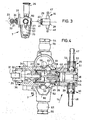
- FIG. 2 shows the usual arrangement of the fuel delivery pump 7 on the injection pump 9, i.e. the fuel feed pump 7 is attached directly to the injection pump 9 by means of a flange 20 formed thereon.
- the other units assigned to the injection pump 9 should also be mentioned, namely a speed controller 21, a clutch 22 provided between the crankshaft of the engine (not shown) and the invisible camshaft of the injection pump 9, and an injection adjuster 23.
- 24 is one of the pressure valves referred to as the 'injection pump 9.
- a filter 25 and a hand pump 26 are assigned to the fuel feed pump 7 on the suction side, while the piston chamber of the fuel feed pump 7 is closed by a screw 27.
- FIG. 3 is a further view of the fuel feed pump 7 and a view of the auxiliary pump 14.
- This illustration shows the simple manner in which the auxiliary pump 14 can be mounted if a threaded shoulder 29 corresponding to the thread of the screw plug 27 is formed on its housing 28.
- the FIG. 3 also shows that in the assembled state of the fuel delivery pump 7, a roller 31 which projects from the fuel delivery pump 7 and is mounted in a roller carrier 30 is in frictional engagement with an eccentric 33 arranged on the injection pump camshaft 32.
- roller carrier 30 is guided in a bore 34 and secured against rotation by means of a double tongue and groove connection - one is designated 35/36.
- the roller carrier 30 acts, as can also be seen, on a pressure pin 37 which is slidably mounted in the housing 28 of the fuel delivery pump 7 and on which the delivery piston 40 of the fuel delivery pump 7, which is guided in the piston bore 38 and is under the action of a piston spring 39, is supported.
- the screw 27 of the piston spring 39 serves as a counter bearing.
- the piston spring 39 is supported on the housing 28 of the auxiliary pump 14 or on a bearing part 41 pressed into the housing 28.
- a plunger 42 is guided, which, when the addition p umpe 146an.
- Fuel feed pump 7 is screwed, under the action of a spring 43 on the one hand with the delivery piston 40, on the other hand with a bore 44 formed in the housing 28 of the auxiliary pump 14 piston 45 is operatively connected.
- the plunger 42 and the spring 43 thus represent the already mentioned and shown in FIG. 1 denoted by 19, mechanical coupling.
- the suction and pressure chamber 46 of the auxiliary pump 14 are associated with hose connecting pieces 47 and 48, into which ball valves 49 and 50, which act as check valves and each consist of a ball 51, a spring 52 and a ball cage 53, are integrated.
- the fuel pump 7, both suction side and pressure side by means of a hollow bolt 54 or 55 fixed ring tube - connection 56 and 57 in the respective fuel circuit is in integration and in that the suction and pressure side in each case a check valve - in FIG. 4, only the respective valve seat 58 or 59 and the components supporting the check valve springs, i.e. on the one hand the hand pump 26 or its housing which can be screwed into the valve chamber and on the other hand a screw plug 60 is shown, which connects the respective channel 61 or 62 to the suction chamber 63 opens or blocks.
- the pressure chamber 64 of the fuel feed pump 7 through a suitable channel 65 with the discharge on the pressure side in Connection is established. With 66 between the fuel pump 7 and the auxiliary pump 14 is provided, preferably soft metal seal.
Landscapes
- Engineering & Computer Science (AREA)
- Chemical & Material Sciences (AREA)
- Combustion & Propulsion (AREA)
- Mechanical Engineering (AREA)
- General Engineering & Computer Science (AREA)
- Fuel-Injection Apparatus (AREA)
Applications Claiming Priority (2)
| Application Number | Priority Date | Filing Date | Title |
|---|---|---|---|
| DE19833304723 DE3304723A1 (de) | 1983-02-11 | 1983-02-11 | Anordnung einer einen zusatzkreislauf im betriebssystem eines dieselmotors speisende zusatzpumpe |
| DE3304723 | 1983-02-11 |
Publications (2)
| Publication Number | Publication Date |
|---|---|
| EP0118681A1 true EP0118681A1 (fr) | 1984-09-19 |
| EP0118681B1 EP0118681B1 (fr) | 1986-07-30 |
Family
ID=6190604
Family Applications (1)
| Application Number | Title | Priority Date | Filing Date |
|---|---|---|---|
| EP84100536A Expired EP0118681B1 (fr) | 1983-02-11 | 1984-01-19 | Disposition d'une pompe additionnelle pour l'alimentation d'un circuit additionnel dans le sytème d'exploitation d'un moteur Diesel |
Country Status (3)
| Country | Link |
|---|---|
| US (1) | US4501251A (fr) |
| EP (1) | EP0118681B1 (fr) |
| DE (2) | DE3304723A1 (fr) |
Cited By (1)
| Publication number | Priority date | Publication date | Assignee | Title |
|---|---|---|---|---|
| EP0308076A3 (fr) * | 1987-09-17 | 1989-10-18 | DELCO ELECTRONICS OVERSEAS CORPORATION (a Delaware corp.) | Dispositif de montage |
Families Citing this family (7)
| Publication number | Priority date | Publication date | Assignee | Title |
|---|---|---|---|---|
| DE3520660A1 (de) * | 1985-06-08 | 1986-12-11 | Bosch Gmbh Robert | Verfahren und vorrichtung zum sicheren betrieb einer brennkraftmaschine |
| GB2204005B (en) * | 1987-04-25 | 1991-05-08 | Lucas Ind Plc | Fuel reservoir |
| DE19531811A1 (de) * | 1995-08-30 | 1997-03-06 | Bosch Gmbh Robert | Kraftstoffeinspritzpumpe |
| US5794598A (en) * | 1996-06-21 | 1998-08-18 | Stanadyne Automotive Corp. | Fuel circuit and circulation method for fuel injection system |
| DE19750036C2 (de) * | 1997-11-12 | 1999-09-02 | Mannesmann Vdo Ag | Kraftstoffördereinrichtung |
| US5878724A (en) * | 1997-12-23 | 1999-03-09 | Ford Global Technologies, Inc. | Diesel vehicle primary fuel pump driven by return fuel energy |
| JP6106792B1 (ja) * | 2016-07-05 | 2017-04-05 | 三井造船株式会社 | 昇圧用ポンプ |
Citations (3)
| Publication number | Priority date | Publication date | Assignee | Title |
|---|---|---|---|---|
| DE1403452A1 (de) * | 1960-06-29 | 1969-10-16 | Acf Ind Inc | Unterdruckzusatzpumpe |
| GB1209838A (en) * | 1968-02-07 | 1970-10-21 | Teves Gmbh Alfred | Improvements in or relating to internal combustion engines |
| EP0059303A2 (fr) * | 1981-02-26 | 1982-09-08 | Mannesmann Kienzle GmbH | Agencement pour refroidir le combustible dans un système de fonctionnement d'un moteur Diesel avec un circuit d'injection fermé |
Family Cites Families (5)
| Publication number | Priority date | Publication date | Assignee | Title |
|---|---|---|---|---|
| US1729723A (en) * | 1920-04-12 | 1929-10-01 | Ind Res Corp | Fuel-feed system |
| US1903481A (en) * | 1929-06-17 | 1933-04-11 | Stewart Warner Corp | Engine-operated pump |
| US2411312A (en) * | 1943-01-20 | 1946-11-19 | William A Yonkers | Fuel delivery system for internal-combustion engines |
| CH477627A (de) * | 1967-12-15 | 1969-08-31 | Von Roll Ag | Hydroaggregat |
| DE2219468A1 (de) * | 1972-04-21 | 1973-10-31 | Bosch Gmbh Robert | Blockierschutzvorrichtung fuer kraftfahrzeuge |
-
1983
- 1983-02-11 DE DE19833304723 patent/DE3304723A1/de not_active Withdrawn
-
1984
- 1984-01-19 EP EP84100536A patent/EP0118681B1/fr not_active Expired
- 1984-01-19 DE DE8484100536T patent/DE3460358D1/de not_active Expired
- 1984-02-08 US US06/578,279 patent/US4501251A/en not_active Expired - Fee Related
Patent Citations (3)
| Publication number | Priority date | Publication date | Assignee | Title |
|---|---|---|---|---|
| DE1403452A1 (de) * | 1960-06-29 | 1969-10-16 | Acf Ind Inc | Unterdruckzusatzpumpe |
| GB1209838A (en) * | 1968-02-07 | 1970-10-21 | Teves Gmbh Alfred | Improvements in or relating to internal combustion engines |
| EP0059303A2 (fr) * | 1981-02-26 | 1982-09-08 | Mannesmann Kienzle GmbH | Agencement pour refroidir le combustible dans un système de fonctionnement d'un moteur Diesel avec un circuit d'injection fermé |
Cited By (1)
| Publication number | Priority date | Publication date | Assignee | Title |
|---|---|---|---|---|
| EP0308076A3 (fr) * | 1987-09-17 | 1989-10-18 | DELCO ELECTRONICS OVERSEAS CORPORATION (a Delaware corp.) | Dispositif de montage |
Also Published As
| Publication number | Publication date |
|---|---|
| DE3460358D1 (en) | 1986-09-04 |
| EP0118681B1 (fr) | 1986-07-30 |
| DE3304723A1 (de) | 1984-08-16 |
| US4501251A (en) | 1985-02-26 |
Similar Documents
| Publication | Publication Date | Title |
|---|---|---|
| DE4315826C5 (de) | Motor-Pumpen-Aggregat | |
| DE3048449C2 (de) | Hilfsgerätebaugruppe | |
| EP0391366B1 (fr) | Appareil d'injection de combustible | |
| DE10237801B4 (de) | Vorrichtung zur Druckregelung von Hydraulikpumpen | |
| EP0149219A2 (fr) | Pompe à piston | |
| DE10220305A1 (de) | Anordnung zum variablen Pumpen von Drucköl und Schmiereinrichtung | |
| DE2731975C3 (de) | Hilfskraftlenkung für Kraftfahrzeuge | |
| EP0118681A1 (fr) | Disposition d'une pompe additionnelle pour l'alimentation d'un circuit additionnel dans le sytème d'exploitation d'un moteur Diesel | |
| DE3615289A1 (de) | Vorrichtung zur klimatisierung eines fahrzeuges | |
| DE2741535A1 (de) | Fluessigkeitspumpe, insbesondere kraftstoff-foerderpumpe | |
| DE19707654A1 (de) | Motor-Pumpenaggregat mit Linearantrieb | |
| DE10063757A1 (de) | Pumpenaggregat für eine hydraulische Fahrzeugbremsanlage | |
| EP0405118A1 (fr) | Pompe rotative à carburant | |
| EP1158181A2 (fr) | Vérin électrohydraulique | |
| AT391012B (de) | Vorschmiersystem fuer ein, ein oelbad aufweisendes verdichter-schmiersystem | |
| EP1074734A2 (fr) | Pompe à pistons axiaux | |
| DE102010038994A1 (de) | Hochdruckpumpe | |
| EP3076041A1 (fr) | Système d'entraînement de frein | |
| WO2007014785A1 (fr) | Soupape de vidange conçue pour un circuit hydraulique | |
| DE3841462C2 (de) | Brennstoffeinspritzvorrichtung | |
| EP2694816B1 (fr) | Régulateur d'air pour compresseurs, en particulier pour compresseurs à vis | |
| DE10119688B4 (de) | Schmierstoffspender | |
| EP2205868B1 (fr) | Pompe destinée en particulier à une unité hydraulique d'un système de freinage de véhicule à réglage électronique | |
| DE9206567U1 (de) | Axialkolbenpumpe | |
| DE102010015932B4 (de) | Solenoidventil für die Durchstromsteuerung |
Legal Events
| Date | Code | Title | Description |
|---|---|---|---|
| PUAI | Public reference made under article 153(3) epc to a published international application that has entered the european phase |
Free format text: ORIGINAL CODE: 0009012 |
|
| AK | Designated contracting states |
Designated state(s): DE FR GB IT SE |
|
| 17P | Request for examination filed |
Effective date: 19841128 |
|
| RAP1 | Party data changed (applicant data changed or rights of an application transferred) |
Owner name: MANNESMANN KIENZLE GMBH |
|
| GRAA | (expected) grant |
Free format text: ORIGINAL CODE: 0009210 |
|
| AK | Designated contracting states |
Kind code of ref document: B1 Designated state(s): DE FR GB IT SE |
|
| ITF | It: translation for a ep patent filed | ||
| REF | Corresponds to: |
Ref document number: 3460358 Country of ref document: DE Date of ref document: 19860904 |
|
| ET | Fr: translation filed | ||
| PLBE | No opposition filed within time limit |
Free format text: ORIGINAL CODE: 0009261 |
|
| STAA | Information on the status of an ep patent application or granted ep patent |
Free format text: STATUS: NO OPPOSITION FILED WITHIN TIME LIMIT |
|
| 26N | No opposition filed | ||
| REG | Reference to a national code |
Ref country code: GB Ref legal event code: 746 |
|
| PGFP | Annual fee paid to national office [announced via postgrant information from national office to epo] |
Ref country code: SE Payment date: 19921228 Year of fee payment: 10 |
|
| ITTA | It: last paid annual fee | ||
| REG | Reference to a national code |
Ref country code: FR Ref legal event code: DL |
|
| PG25 | Lapsed in a contracting state [announced via postgrant information from national office to epo] |
Ref country code: SE Effective date: 19940120 |
|
| EUG | Se: european patent has lapsed |
Ref document number: 84100536.6 Effective date: 19940810 |
|
| PGFP | Annual fee paid to national office [announced via postgrant information from national office to epo] |
Ref country code: FR Payment date: 19951219 Year of fee payment: 13 |
|
| PG25 | Lapsed in a contracting state [announced via postgrant information from national office to epo] |
Ref country code: FR Effective date: 19970930 |
|
| REG | Reference to a national code |
Ref country code: FR Ref legal event code: ST |
|
| PGFP | Annual fee paid to national office [announced via postgrant information from national office to epo] |
Ref country code: DE Payment date: 20000221 Year of fee payment: 17 |
|
| PGFP | Annual fee paid to national office [announced via postgrant information from national office to epo] |
Ref country code: GB Payment date: 20001212 Year of fee payment: 18 |
|
| PG25 | Lapsed in a contracting state [announced via postgrant information from national office to epo] |
Ref country code: DE Free format text: LAPSE BECAUSE OF NON-PAYMENT OF DUE FEES Effective date: 20011101 |
|
| REG | Reference to a national code |
Ref country code: GB Ref legal event code: IF02 |
|
| PG25 | Lapsed in a contracting state [announced via postgrant information from national office to epo] |
Ref country code: GB Free format text: LAPSE BECAUSE OF NON-PAYMENT OF DUE FEES Effective date: 20020119 |
|
| GBPC | Gb: european patent ceased through non-payment of renewal fee |
Effective date: 20020119 |