EP0118905A2 - Adaptive Schwellenschaltung für Bildverarbeitung - Google Patents
Adaptive Schwellenschaltung für Bildverarbeitung Download PDFInfo
- Publication number
- EP0118905A2 EP0118905A2 EP84102604A EP84102604A EP0118905A2 EP 0118905 A2 EP0118905 A2 EP 0118905A2 EP 84102604 A EP84102604 A EP 84102604A EP 84102604 A EP84102604 A EP 84102604A EP 0118905 A2 EP0118905 A2 EP 0118905A2
- Authority
- EP
- European Patent Office
- Prior art keywords
- document
- value
- mean
- binary numbers
- binary
- Prior art date
- Legal status (The legal status is an assumption and is not a legal conclusion. Google has not performed a legal analysis and makes no representation as to the accuracy of the status listed.)
- Withdrawn
Links
Images

Classifications
-
- H—ELECTRICITY
- H04—ELECTRIC COMMUNICATION TECHNIQUE
- H04N—PICTORIAL COMMUNICATION, e.g. TELEVISION
- H04N1/00—Scanning, transmission or reproduction of documents or the like, e.g. facsimile transmission; Details thereof
- H04N1/40—Picture signal circuits
- H04N1/403—Discrimination between the two tones in the picture signal of a two-tone original
-
- G—PHYSICS
- G06—COMPUTING OR CALCULATING; COUNTING
- G06T—IMAGE DATA PROCESSING OR GENERATION, IN GENERAL
- G06T5/00—Image enhancement or restoration
- G06T5/20—Image enhancement or restoration using local operators
-
- G—PHYSICS
- G06—COMPUTING OR CALCULATING; COUNTING
- G06T—IMAGE DATA PROCESSING OR GENERATION, IN GENERAL
- G06T7/00—Image analysis
- G06T7/10—Segmentation; Edge detection
- G06T7/12—Edge-based segmentation
-
- G—PHYSICS
- G06—COMPUTING OR CALCULATING; COUNTING
- G06T—IMAGE DATA PROCESSING OR GENERATION, IN GENERAL
- G06T2207/00—Indexing scheme for image analysis or image enhancement
- G06T2207/10—Image acquisition modality
- G06T2207/10004—Still image; Photographic image
- G06T2207/10008—Still image; Photographic image from scanner, fax or copier
-
- G—PHYSICS
- G06—COMPUTING OR CALCULATING; COUNTING
- G06T—IMAGE DATA PROCESSING OR GENERATION, IN GENERAL
- G06T2207/00—Indexing scheme for image analysis or image enhancement
- G06T2207/20—Special algorithmic details
- G06T2207/20004—Adaptive image processing
- G06T2207/20012—Locally adaptive
-
- G—PHYSICS
- G06—COMPUTING OR CALCULATING; COUNTING
- G06T—IMAGE DATA PROCESSING OR GENERATION, IN GENERAL
- G06T2207/00—Indexing scheme for image analysis or image enhancement
- G06T2207/30—Subject of image; Context of image processing
- G06T2207/30176—Document
Definitions
- This invention relates to digital coding apparatus used in digitizing images on a document for reproduction, storage and/or transmission to recreate the document.
- a document containing images or indicia such as printed information is-illuminated, scanned, and light reflected from the scanned document is detected creating an analog electrical signal which is processed to determine if portions along a scanned path are black or white in order to distinguish between the background of the document and the indicia contained thereon.
- documents are scanned and digitized and binary decision logic is usually employed to determine a threshold level between black and white used for converting the analog signal output from the scanner to a two level binary signal wherein each level corresponds to black or white detected reflections from portions or pixels of the scanned document. It is known that such detected reflections from a scanned document vary widely not only from sheet to sheet but also from portion to portion on a document.
- the magnitude of the signal generated by a photo detector in scanning a document is a function of the light reflected from the scanned document.
- the signal amplitude is also influenced by variations in document illumination, smudges, document background colors, defects in the image itself, and variations in the sensitivity of the photo detectors. Accordingly, it is necessary to extract the desired components in the analog signal due to image content and to supress the undesirable, abovementioned variations from the analog signal.
- This separation is generally accomplished by establishing a threshold value against which the reflected signal is compared.
- the result of the comparison is a binary decision such that whenever the reflectance value exceeds the threshold one color, e.g. white, is selected and, conversely, where the threshold is not exceeded, the opposite color, e.g. black, is selected.
- the binary decision is represented by a zero or a one for a number of sample points or pixels on a document.
- U.S. Patent 4,345,314 teaches a technique in which analog signals for 2,048 pixels in a scan line must be digitized and stored. In addition, 2,048 vertical reference values must be stored. Thus, in excess of four thousand 8-bit binary words must be stored for analyzation to adjust the threshold level used in making the black-white decision for each pixel.
- the technique described consists of a two-dimensional low pass filter which is used to estimate only the mean reflectance value in areas near the pixels to be thresholded. As such, the technique is sensitive to the percentage of indicia in the document which is an undesirable feature. This technique requires a large amount of memory to implement.
- U.S. Patent 4,247,873 teaches a technique in which a peak detector is utilized to detect the peaks of analog signals representing light reflected from the document.
- the analog signals are integrated by charging a capacitor from which the charge is dissipated across one of two parallel resistors.
- a very slow decay rate is implemented by a large value resistor when the overall reflected light level from a scanned document is high, and a higher discharge rate is implemented by placing a smaller value resistor in parallel with the capacitor when the overall reflectivity from the document is lower.
- the effect of the smaller value resistor in parallel with the capacitor is to lower the voltage across the capacitor. It is this voltage across the capacitor which is representative of the threshold voltage.
- the threshold goes up as the overall light reflected from a document during scanning is higher, and the threshold value goes down whenoverall reflected light is lower.
- a comparator is then used to compare an analog signal representative of the light reflected from a particular sample point or pixel being scanned with the threshold level to determine if the particular pixel is black or white.
- the same binary numbers representing pixels in each column are also processed as they are generated to compute a mean-above-mean value for mean peak value for each column which indicates the signal level corresponding to white on the document. Thereafter, the mean peak value for each column is used to calculate a threshold value for each column. More particularly, the mean peak value for a specific column is used in conjunction with the mean peak value for the contiguous columns to calculate the threshold value. The threshold value for each column is updated each time the given column is rescanned for subsequent scan lines across the document. In this manner accurate threshold values are determined.
- the updated mean value for each column is compared to the value of each binary number representing a pixel scanned in the corresponding column and when the value of a binary number exceeds the updated mean value the mean peak value for the same column is updated. When the value of a binary number representing a point in an column does not exceed the updated mean value the mean peak value for the column is not updated.
- the updated threshold value for each column is compared to each binary number representing each pixel in the same column.
- a first state of a two state signal is generated.
- the threshold value is less than the value of a binary number the opposite value of the two state signal is generated.
- these two states are the zero and one of a binary signal with the one state representing a white pixel on the document and the zero state representing a black pixel on the document.
- Figure 1 is seen a block diagram of the preferred embodiment of a system implementing our invention.
- This embodiment is utilized in a facsimile system to process digitized signals from a scanner representing a document to derive a processed digitized image signal which may be transmitted to a remote location and thereat used to construct an accurate copy of the document that is being transmitted utilizing the facsimile equipment.
- Our invention may also be used in other applications wherein a document is scanned and a digital signal is obtained representing the document to be used for some purpose. For example, in such applications as copiers and laser printers.
- element 10 represents a document on which is an image or other indicia (not shown) which most likely will be alphanumeric characters.
- a scanning device 11 is utilized to scan document 10 to create-an analog signal representative of the image or other indicia thereon.
- scanner 11 is a charge coupled device (CCD) array such as taught in U.S. Patent 4,351,004 which is incorporated herein by reference.
- CCD array 11 has a plurality of elements located in a row across the width of document 10. Each of the plurality of CCD elements is responsive to light to generate .an analog signal output corresponding to the intensity of the light impinging thereon by means of the imaging lens. Circuity is provided, with CCD array 11 as described in U.S.
- Patent 4,351,004 which is used to periodically and cyclically read individual ones of the CCD elements in array 11. This creates a scanning action to scan document 10. In this manner document 10 is scanned creating an analog signal output from array 11 representative of the image or other indicia on document 10.
- the analog signal output from array 11 is applied to and conditioned by filter 12 which is a low pass filter made up of a resistor and capacitor network coupled to an operational amplifier as is well known in the art.
- the analog signal output from filter 12 is then applied to analog-to-digital converter 13 which, in a manner well known in the art, periodically samples the analog signal and generates binary numbers representative of the amplitude of each sample of the analog signal. Each sample is termed a pixel in the art.
- Microprocessor 19 utilizes the digitized signals input to it via buffer circuit 14 to derive a variable threshold signal, which is described in greater detail hereinafter, and the variable threshold signal is applied via bus 17, leads 22, and temporarily stored in buffer circuit 24 to be applied to one of two inputs of comparator 16.
- a variable threshold signal which is described in greater detail hereinafter
- the variable threshold signal is applied via bus 17, leads 22, and temporarily stored in buffer circuit 24 to be applied to one of two inputs of comparator 16.
- each of the binary signals output from analog-to-digital converter 13 were also individually stored in buffer circuit 15.
- Comparator 16 compares each binary number momentarily stored in buffer circuit 15 with the variable threshold signal in binary word form stored in buffer circuit 24. When the value of the variable threshold signal is greater than or equal to the value of the binary number stored in buffer circuit 15, the output from comparator 16 on lead 23 to bus 17 is a binary one which indicates that the scanned point represented by the binary number presently stored in buffer circuit 15 is black.
- variable threshold value is determined by comparator 16 to have a value less than the binary number momentarily stored in buffer circuit 1 5 a binary zero is output on lead 23 from comparator 16 indicating that the scanned point represented by the binary number presently stored in buffer circuit 15 is white.
- comparator 23 there is a string of binary zeros and ones output from comparator 23 on lead 23 which is the processed digitized image signal that is output via output circuit 21. Details of the processing of the binary numbers input to microprocessor 19 to create the variable threshold signal applied to comparator circuit 16 is described immediately hereinafter.
- Microprocessor 19 processes the digitized document information input to it via buffer circuit 14. Before describing the details of this processing, however, we first describe the layout of the document for scanning and the minimal memory requirements created by our novel mode of processing the digitized signals.
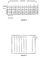
- FIG. 2 is shown the layout of document 10 utilized in our signal processing technique.
- Document 10 is divided into a total of twenty-seven columns of equal width.
- CCD array 11 extends across document 10 orthogonal to the twenty-seven columns just referred to.
- Array 11 has 1,728 CCD detector elements which are sequentially read out in a time division multiplexing mode to scan a line which covers the breadth of document 10.
- the 1,728 CCD elements are divided into twenty-seven groups of 64 elements. Each of these twenty-seven columns has four multi-bit words of memory associated with it for a total of 108 words of memory.
- the four word locations in memory associated with each of the twenty-seven columns are used to store a "mean" value of the analog signal output from CCD array 11, a "mean-above-mean” or mean peak value of the same analog information, a "current mean gain constant", and a "current mean-above-mean gain constant”.
- the two constants are utilized in the processing steps described further in this specification to calculate the mean and the mean peak values. These values and the constants are calculated for each of the twenty-seven columns on document 10 and then are updated for each scan line across document 10 to achieve the adaptive threshold function provided by our novel invention. If processor 19 can't calculate the values and constants for each line, mean values may be calculated say on odd scan lines and mean peak values calculated on even scan lines.
- the mean and mean peak values are stored and updated for each of the twenty-seven columns to follow changes both horizontally and vertically on document 10.
- CCD array 11 has a total of sixty-four elements for-each of the twenty-seven columns of document 10 only the output of every eighth element is utilized in this particular embodiment of our invention. This is merely constrained by the operating speed of microprocessor 19 and those skilled in the art may use multiple processing or faster processors to process more samples. In this embodiment of our invention, using the output of every eighth element of CCD array 11 does not degrade the performance of our invention. With our mode of processing the document is digitized and the information is.processed on-the-fly so that little memory is required. Since only a small amount of memory is required buffer memory 18 is not a separate memory from microprocessor 19 but, in reality, is a small amount of memory available within the microprocessor chip.
- Microprocessor 19 processes the digitized document information input thereto to first derive a psuedo average or mean of the signal utilizing equation (A) immediately hereinbelow.
- Equation (A) represents a digital filter having one pole with unity gain and a bandwith determined by the value of S l,i .
- Equation (A) utilizes the binary number representing the amplitude of the light reflected from each sample point or pixel on document 10 as P n,i and utilizes the mean value (m n-l,i ) derived for the previous one of the eight pixels within each column on document 10.
- S l,i is the "current mean gain constant" which is one of the four multi-bit binary words stored for each of the twenty-seven columns of document 10. Initially S l,i is assigned a value of one and is then decreased to a value of 1/128 over the eight pixels of each column of the first scan line.
- the resulting time-varying filter is initially a wide-band low-pass filter. As S l,i decreases it changes to a narrow-band low-pass filter. This allows the scanning function to start with the white background at the edge of a document and then proceed during scanning to the black images or other indicia which are usually alphanumeric characters.
- the digital filter represented by equation (A) is not a true averaging technique but it does average out the mean by considering the nature of the document around each pixel and thereby prevents fluctuations in the reproduced document which are objectionable. Starting at the beginning of scanning of the first scan line of a document the value of S l,i in equation (A) is given the value of one for the first pixel.
- This value of S l,i is initially utilized for the mean calculation using equation (A) for the first pixel of each of the twenty-seven columns along the first scan line. For each subsequent pixel the value of S l,i is halved, such that for the second pixel S l,i equals 1/2, for the third pixel S l,i equals 1/4, and so on to the eighth pixel in section i for which S l,i equals 1/128. For the second and subsequent lines S l,i equals 1/256 for all pixels in all columns and this value for S l,i that is maintained over the remainder of the document. S l,i is the current mean gain constant which is stored in one of the four words in memory associated with column i.
- equation (A) Carrying the analyzation of equation (A) to the third pixel the value of P for the first sample is P n-2,i and the value of P for the second sample is now P n-1,i . Accordingly for the third pixel in each column m n,i equals 3/8 P n-2 , i + 3/8 P n-l,1 + 1/4 P n,i .
- equation (A) performs its psuedo averaging technique to derive the mean value "m" by adding in only a fraction of the reflectance from each pixel into the summation.
- the filter has the effect of weighting the most recent pixels most heavily (exponential weighting).
- Equation (A) we are continuously updating the mean value "m" for each of the twenty-seven columns of document 10 using the digitized reflectance value P n , i for each pixel.
- the mean value at that point in time is stored in one of the four words of memory assigned to each of the twenty-seven columns.
- the mean value for each column is again updated for each of the eight samples in each column and the new updated mean value is again stored in memory.
- the mean value "m" for each of the twenty-seven columns is continuously updated as an entire document is scanned.
- microprocessor 19 After an updated mean value is calculated for each column the next step performed by microprocessor 19 is to compare the updated mean value with each reflectance value P n,i in the associated column. Only in the event that the reflectance value P n,i is greater in value than the current updated mean value, does microprocessor 19 go to the next calculation step to calculate an updated value for a mean-above-mean or mean peak value of the digitized data. When the opposite condition occurs on comparison nothing is done. This comparison of the digitized reflectance value P ni for each document sample point or pixel to the digitized udated mean value is done to take into account many factors including the background of document 10 being colored and there being a large quantity of colored or black image or indicia on document 10.
- equation (B) is similar to equation (A).
- a current mean-above-mean (mam) value is calculated using the previous value of mam, a value S 2,i and the present digitized value of reflectance P n i from the document during scanning.
- the value of mam is not calculated for each pixel of the document but is updated only when P n,i is greater than m n,i .
- Equation (B) is also for a digital filter having one pole and unity gain with a bandwidth determined by the value of S 2,i .
- Figure 3 is seen a table which facilitates a better understanding of when the value of mam is updated.
- Figure 3 shows a total of eight columns which represent the eight samples or pixels within each of the twenty-seven columns across a document.
- the third row of Figure 3 is designated S 1,i and reflects the values of S 1,i used in equation (A) for the first scan line and for each of the eight samples in each of the twenty-seven columns.
- the first line of Figure 3 represents the comparison of the reflectance value P n,i to the mean value "m" calculated using equation (A).
- the second row of Figure 3 represents the values of S 291 utilized in equation (B). Initially, S 2,i has a value of one.
- each column of the twenty-seven columns across document 10 has a continuously updated value of the mean value "m” and the mean-above-mean value "mam", the current mean gain constant S l,i and the current mam gain constant S 2,i stored in the four binary words in memory associated with each of the twenty-seven columns.
- the mean value "m” is used as described to decide if the mean-above-mean or mean peak value "mam” should be updated as previously described.
- the "mam" values for each of the --twenty-seven columns are used to derive our adaptive threshold used in processing the digitized signal samples derived from scanning document 10 as now described.
- Equation (C) immediately herein below is utilized to calculate the adaptive threshold value, TH n,i .
- Equation (C) has a constant k that does not vary automatically but may be manually varied by the operator of the facsimile equipment or other equipment in which our invention is utilized.
- K has a nominal value of 0.75 that may be manually varied over a range of 0.60 to 0.90 to either lighten or darken the document transmitted and recreated utilizing the facsimile process.
- Equation (C) utilizes the values for mam for three contiguous columns on document 10.
- a filtering takes place such that the threshold value does not change radically from column to column across a document.
- the threshold value is equal to the constant k times the sum of 1/2 the mam value for column one plus 1/2 the mam value for column two.
- the threshold value is equal to the constant k times the sum of 1/2 times the mam value for column twenty-six plus 1/2 mam value of column twenty-seven.
- the threshold value for a column is calculated immediately preceeding the arrival of the binary number for the first of the sixty-four samples or pixels for each column.
- the threshold value is thereafter compared to the reflectance value P n i for each of the sixty-four samples by comparator 17 in Figure 1.
- the threshold value is greater than the value of P n i it is determined that the sample is black and a zero is generated.
- the threshold value is less than or equal to the value of P n,i the sample is determined to be white and the signal a binary one is generated.
- a stream of zeros and ones is generated representing the document and this stream of zeros and ones is the processed digitized image signal.
- the digitized value of reflectance P n,i is a binary number placed in buffer 15 and then applied to a first of the two inputs of comparator 16. As P n,i for each of the sixty-four samples for each column is generated it is sequentially applied to this first input of comparator 16. During the time that these sixty-four digitized samples are being applied to the first input of comparator 16 microprocessor 19 has previously determined the threshold value for the column and applies this value in binary form via leads 22 to buffer 24 to then be applied to a second input of comparator 16. As a result of the comparison, the zeros and ones generated are output on lead 23 and via output circuit 21 for transmission to a remote location to reconstruct the document.
Landscapes
- Engineering & Computer Science (AREA)
- Physics & Mathematics (AREA)
- General Physics & Mathematics (AREA)
- Theoretical Computer Science (AREA)
- Multimedia (AREA)
- Signal Processing (AREA)
- Computer Vision & Pattern Recognition (AREA)
- Facsimile Image Signal Circuits (AREA)
- Character Input (AREA)
Applications Claiming Priority (2)
| Application Number | Priority Date | Filing Date | Title |
|---|---|---|---|
| US47437683A | 1983-03-11 | 1983-03-11 | |
| US474376 | 1983-03-11 |
Publications (2)
| Publication Number | Publication Date |
|---|---|
| EP0118905A2 true EP0118905A2 (de) | 1984-09-19 |
| EP0118905A3 EP0118905A3 (de) | 1986-11-26 |
Family
ID=23883251
Family Applications (1)
| Application Number | Title | Priority Date | Filing Date |
|---|---|---|---|
| EP84102604A Withdrawn EP0118905A3 (de) | 1983-03-11 | 1984-03-09 | Adaptive Schwellenschaltung für Bildverarbeitung |
Country Status (5)
| Country | Link |
|---|---|
| US (1) | US4850029A (de) |
| EP (1) | EP0118905A3 (de) |
| JP (1) | JP2597350B2 (de) |
| AU (1) | AU565874B2 (de) |
| CA (1) | CA1207909A (de) |
Cited By (4)
| Publication number | Priority date | Publication date | Assignee | Title |
|---|---|---|---|---|
| GB2226734A (en) * | 1988-12-05 | 1990-07-04 | Mitsubishi Electric Corp | Digital binarization circuit for conversion of image data |
| US5268773A (en) * | 1990-03-30 | 1993-12-07 | Samsung Electronics Co., Ltd. | Document image signal processor having an adaptive threshold |
| GB2317775A (en) * | 1996-09-24 | 1998-04-01 | Daewoo Electronics Co Ltd | Binarizing compensation apparatus and method |
| KR100492529B1 (ko) * | 1997-12-23 | 2005-10-26 | 엘지전자 주식회사 | 적응 단순 이진화 영상처리방법 |
Families Citing this family (16)
| Publication number | Priority date | Publication date | Assignee | Title |
|---|---|---|---|---|
| US4613986A (en) * | 1984-06-14 | 1986-09-23 | Ncr Canada Ltd. | Digital filter for enhancement of document images |
| US4839721A (en) * | 1984-08-28 | 1989-06-13 | Polaroid Corporation | Method of and apparatus for transforming color image data on the basis of an isotropic and uniform colorimetric space |
| US5208873A (en) * | 1987-09-10 | 1993-05-04 | Minolta Camera Kabushiki Kaisha | Image reader having an editor for setting a threshold value |
| US5245677A (en) * | 1991-08-08 | 1993-09-14 | Hughes Aircraft Company | Directional running average segmentation |
| CA2063621C (en) * | 1991-10-03 | 1999-03-16 | Wayne M. Doran | Method and modular system for high speed processing of item images |
| US5335297A (en) * | 1992-01-17 | 1994-08-02 | The United States Of Americas As Represented By The Secretary Of The Navy | Target detection for vision systems |
| JPH0646255A (ja) * | 1992-07-23 | 1994-02-18 | Fuji Xerox Co Ltd | 画像処理装置 |
| EP0731951B1 (de) * | 1993-02-26 | 2000-07-05 | E-Y Laboratories, Inc. | Optisches probe-analysesystem und verfahren |
| US5617489A (en) * | 1993-08-04 | 1997-04-01 | Richard S. Adachi | Optical adaptive thresholder for converting analog signals to binary signals |
| US5404232A (en) * | 1993-10-04 | 1995-04-04 | Xerox Corporation | Calibration system for a raster input scanner |
| SE506145C2 (sv) * | 1995-03-20 | 1997-11-17 | Bjoern Stefan Christian Blixt | Förfarande för omvandling av en i bildelement uppdelad gråskalebild till en svart-vit bild |
| GB2317007B (en) * | 1996-09-04 | 2000-07-26 | Spectrum Tech Ltd | Contrast determining apparatus and methods |
| JP2002502980A (ja) * | 1998-02-10 | 2002-01-29 | イーワイ ラボラトリーズ インコーポレイテッド | 試料ホルダ起伏形状を補償し且つシステム・ノイズのロック除去を行う反射測定システム |
| US6631215B1 (en) * | 1999-11-23 | 2003-10-07 | Xerox Corporation | Method and apparatus for implementing integrated cavity effect correction in scanners |
| JP2006098217A (ja) * | 2004-09-29 | 2006-04-13 | Fujitsu Ltd | 画像検査装置、画像検査方法及び画像検査プログラム |
| US8073284B2 (en) * | 2008-04-03 | 2011-12-06 | Seiko Epson Corporation | Thresholding gray-scale images to produce bitonal images |
Family Cites Families (6)
| Publication number | Priority date | Publication date | Assignee | Title |
|---|---|---|---|---|
| JPS5218132A (en) * | 1975-08-01 | 1977-02-10 | Hitachi Ltd | Binary circuit |
| US4205341A (en) * | 1978-01-24 | 1980-05-27 | Nippon Telegraph And Telephone Public Corporation | Picture signal coding apparatus |
| JPS5668873A (en) * | 1979-11-08 | 1981-06-09 | Fujitsu Ltd | Picture signal binary system |
| US4351004A (en) * | 1980-01-31 | 1982-09-21 | Texas Instruments Incorporated | CCD Imager |
| US4345314A (en) * | 1980-11-19 | 1982-08-17 | International Business Machines Corporation | Dynamic threshold device |
| US4468704A (en) * | 1982-10-28 | 1984-08-28 | Xerox Corporation | Adaptive thresholder |
-
1983
- 1983-10-07 AU AU19959/83A patent/AU565874B2/en not_active Ceased
- 1983-12-13 JP JP58234936A patent/JP2597350B2/ja not_active Expired - Lifetime
-
1984
- 1984-02-21 CA CA000447936A patent/CA1207909A/en not_active Expired
- 1984-03-09 EP EP84102604A patent/EP0118905A3/de not_active Withdrawn
-
1985
- 1985-07-15 US US06/754,685 patent/US4850029A/en not_active Expired - Lifetime
Cited By (6)
| Publication number | Priority date | Publication date | Assignee | Title |
|---|---|---|---|---|
| GB2226734A (en) * | 1988-12-05 | 1990-07-04 | Mitsubishi Electric Corp | Digital binarization circuit for conversion of image data |
| US5166808A (en) * | 1988-12-05 | 1992-11-24 | Mitsubishi Denki Kabushiki Kaisha | Digital binarization circuit for conversion of image data |
| GB2226734B (en) * | 1988-12-05 | 1993-05-12 | Mitsubishi Electric Corp | Digital binarization circuit for conversion of image data |
| US5268773A (en) * | 1990-03-30 | 1993-12-07 | Samsung Electronics Co., Ltd. | Document image signal processor having an adaptive threshold |
| GB2317775A (en) * | 1996-09-24 | 1998-04-01 | Daewoo Electronics Co Ltd | Binarizing compensation apparatus and method |
| KR100492529B1 (ko) * | 1997-12-23 | 2005-10-26 | 엘지전자 주식회사 | 적응 단순 이진화 영상처리방법 |
Also Published As
| Publication number | Publication date |
|---|---|
| CA1207909A (en) | 1986-07-15 |
| US4850029A (en) | 1989-07-18 |
| EP0118905A3 (de) | 1986-11-26 |
| AU1995983A (en) | 1984-09-13 |
| AU565874B2 (en) | 1987-10-01 |
| JP2597350B2 (ja) | 1997-04-02 |
| JPS59175281A (ja) | 1984-10-04 |
Similar Documents
| Publication | Publication Date | Title |
|---|---|---|
| US4850029A (en) | Adaptive threshold circuit for image processing | |
| EP0521662B1 (de) | Verbessertes automatisches Segmentieren von Bildern | |
| EP0041400B1 (de) | Anordnung und Verfahren zur Verarbeitung von Bildsignalen mit mehrfacher Auflösung | |
| US4447830A (en) | Image scanning apparatus and method | |
| EP0070161A2 (de) | Vorrichtung und Verfahren für die adaptive Bestimmung einer Schwellenhöhe | |
| JP3046493B2 (ja) | 画像処理装置 | |
| JPH06103923B2 (ja) | 画像処理方法及び装置 | |
| EP0052187A2 (de) | Schwellenschaltung für ein eine optische Dichte darstellendes Eingangssignal | |
| US6775031B1 (en) | Apparatus and method for processing images, image reading and image forming apparatuses equipped with the apparatus, and storage medium carrying programmed-data for processing images | |
| JPS62172867A (ja) | 画像処理装置 | |
| CA1306540C (en) | Image-processing apparatus | |
| US6539125B1 (en) | Modified median filter that better preserves textures | |
| US5315405A (en) | Binary circuit of scanner read image data | |
| EP0870276B1 (de) | Verfahren zum umsetzen eines grautonbildes in ein schwarz-weiss-bild | |
| EP0195925B1 (de) | Verfahren zum Umwandeln von Bildgraupegeln | |
| US5299030A (en) | Image data processing method and apparatus with mixture of simple binarization and psuedo intermediate tone | |
| US4853793A (en) | Circuit for converting a video signal produced by a line image sensor into a binary signal on the basis of reference levels determined for sections of the line image sensor using respective counters | |
| JPS5840976A (ja) | 画像記録方法 | |
| EP0531923A2 (de) | Verfahren und Gerät zur Grautonquantizierung | |
| JPH05292312A (ja) | 網点領域分離装置 | |
| JPS6180964A (ja) | 画信号処理方法 | |
| JP2994651B2 (ja) | 輪郭画像形成装置 | |
| KR920008327B1 (ko) | 화상신호 전처리장치 | |
| JPH03244277A (ja) | 画像処理装置 | |
| JPH0561677B2 (de) |
Legal Events
| Date | Code | Title | Description |
|---|---|---|---|
| PUAI | Public reference made under article 153(3) epc to a published international application that has entered the european phase |
Free format text: ORIGINAL CODE: 0009012 |
|
| AK | Designated contracting states |
Designated state(s): BE DE FR GB |
|
| PUAL | Search report despatched |
Free format text: ORIGINAL CODE: 0009013 |
|
| AK | Designated contracting states |
Kind code of ref document: A3 Designated state(s): BE DE FR GB |
|
| 17P | Request for examination filed |
Effective date: 19870511 |
|
| STAA | Information on the status of an ep patent application or granted ep patent |
Free format text: STATUS: THE APPLICATION IS DEEMED TO BE WITHDRAWN |
|
| 18D | Application deemed to be withdrawn |
Effective date: 19881001 |
|
| RIN1 | Information on inventor provided before grant (corrected) |
Inventor name: MESSINA, VINCENT JOSEPH Inventor name: MOYER, ALAN LEE |