EP0118937B1 - Druckregelvorrichtung - Google Patents
Druckregelvorrichtung Download PDFInfo
- Publication number
- EP0118937B1 EP0118937B1 EP84200173A EP84200173A EP0118937B1 EP 0118937 B1 EP0118937 B1 EP 0118937B1 EP 84200173 A EP84200173 A EP 84200173A EP 84200173 A EP84200173 A EP 84200173A EP 0118937 B1 EP0118937 B1 EP 0118937B1
- Authority
- EP
- European Patent Office
- Prior art keywords
- chamber
- diaphragm
- restriction
- conduit
- regulating system
- Prior art date
- Legal status (The legal status is an assumption and is not a legal conclusion. Google has not performed a legal analysis and makes no representation as to the accuracy of the status listed.)
- Expired
Links
- 230000001105 regulatory effect Effects 0.000 title claims abstract description 21
- 238000002485 combustion reaction Methods 0.000 claims abstract description 20
- 239000000446 fuel Substances 0.000 claims description 29
- 238000013016 damping Methods 0.000 claims description 11
- 230000001276 controlling effect Effects 0.000 claims description 7
- 239000000203 mixture Substances 0.000 abstract description 4
- 239000007789 gas Substances 0.000 description 37
- 230000001419 dependent effect Effects 0.000 description 4
- 230000033228 biological regulation Effects 0.000 description 2
- 230000035945 sensitivity Effects 0.000 description 2
- 230000006978 adaptation Effects 0.000 description 1
- QVGXLLKOCUKJST-UHFFFAOYSA-N atomic oxygen Chemical compound [O] QVGXLLKOCUKJST-UHFFFAOYSA-N 0.000 description 1
- 238000007664 blowing Methods 0.000 description 1
- 230000007423 decrease Effects 0.000 description 1
- 230000003247 decreasing effect Effects 0.000 description 1
- 230000001627 detrimental effect Effects 0.000 description 1
- 230000000694 effects Effects 0.000 description 1
- 230000003993 interaction Effects 0.000 description 1
- 239000007788 liquid Substances 0.000 description 1
- 239000012528 membrane Substances 0.000 description 1
- 239000001301 oxygen Substances 0.000 description 1
- 229910052760 oxygen Inorganic materials 0.000 description 1
- 239000000126 substance Substances 0.000 description 1
Images

Classifications
-
- G—PHYSICS
- G05—CONTROLLING; REGULATING
- G05D—SYSTEMS FOR CONTROLLING OR REGULATING NON-ELECTRIC VARIABLES
- G05D16/00—Control of fluid pressure
- G05D16/14—Control of fluid pressure with auxiliary non-electric power
- G05D16/16—Control of fluid pressure with auxiliary non-electric power derived from the controlled fluid
- G05D16/163—Control of fluid pressure with auxiliary non-electric power derived from the controlled fluid using membranes within the main valve
-
- F—MECHANICAL ENGINEERING; LIGHTING; HEATING; WEAPONS; BLASTING
- F02—COMBUSTION ENGINES; HOT-GAS OR COMBUSTION-PRODUCT ENGINE PLANTS
- F02D—CONTROLLING COMBUSTION ENGINES
- F02D19/00—Controlling engines characterised by their use of non-liquid fuels, pluralities of fuels, or non-fuel substances added to the combustible mixtures
- F02D19/02—Controlling engines characterised by their use of non-liquid fuels, pluralities of fuels, or non-fuel substances added to the combustible mixtures peculiar to engines working with gaseous fuels
- F02D19/021—Control of components of the fuel supply system
- F02D19/022—Control of components of the fuel supply system to adjust the fuel pressure, temperature or composition
-
- F—MECHANICAL ENGINEERING; LIGHTING; HEATING; WEAPONS; BLASTING
- F02—COMBUSTION ENGINES; HOT-GAS OR COMBUSTION-PRODUCT ENGINE PLANTS
- F02M—SUPPLYING COMBUSTION ENGINES IN GENERAL WITH COMBUSTIBLE MIXTURES OR CONSTITUENTS THEREOF
- F02M21/00—Apparatus for supplying engines with non-liquid fuels, e.g. gaseous fuels stored in liquid form
- F02M21/02—Apparatus for supplying engines with non-liquid fuels, e.g. gaseous fuels stored in liquid form for gaseous fuels
- F02M21/0218—Details on the gaseous fuel supply system, e.g. tanks, valves, pipes, pumps, rails, injectors or mixers
- F02M21/023—Valves; Pressure or flow regulators in the fuel supply or return system
- F02M21/0239—Pressure or flow regulators therefor
-
- F—MECHANICAL ENGINEERING; LIGHTING; HEATING; WEAPONS; BLASTING
- F02—COMBUSTION ENGINES; HOT-GAS OR COMBUSTION-PRODUCT ENGINE PLANTS
- F02M—SUPPLYING COMBUSTION ENGINES IN GENERAL WITH COMBUSTIBLE MIXTURES OR CONSTITUENTS THEREOF
- F02M21/00—Apparatus for supplying engines with non-liquid fuels, e.g. gaseous fuels stored in liquid form
- F02M21/02—Apparatus for supplying engines with non-liquid fuels, e.g. gaseous fuels stored in liquid form for gaseous fuels
- F02M21/06—Apparatus for de-liquefying, e.g. by heating
-
- F—MECHANICAL ENGINEERING; LIGHTING; HEATING; WEAPONS; BLASTING
- F02—COMBUSTION ENGINES; HOT-GAS OR COMBUSTION-PRODUCT ENGINE PLANTS
- F02M—SUPPLYING COMBUSTION ENGINES IN GENERAL WITH COMBUSTIBLE MIXTURES OR CONSTITUENTS THEREOF
- F02M21/00—Apparatus for supplying engines with non-liquid fuels, e.g. gaseous fuels stored in liquid form
- F02M21/02—Apparatus for supplying engines with non-liquid fuels, e.g. gaseous fuels stored in liquid form for gaseous fuels
- F02M21/04—Gas-air mixing apparatus
- F02M21/047—Venturi mixer
-
- Y—GENERAL TAGGING OF NEW TECHNOLOGICAL DEVELOPMENTS; GENERAL TAGGING OF CROSS-SECTIONAL TECHNOLOGIES SPANNING OVER SEVERAL SECTIONS OF THE IPC; TECHNICAL SUBJECTS COVERED BY FORMER USPC CROSS-REFERENCE ART COLLECTIONS [XRACs] AND DIGESTS
- Y02—TECHNOLOGIES OR APPLICATIONS FOR MITIGATION OR ADAPTATION AGAINST CLIMATE CHANGE
- Y02T—CLIMATE CHANGE MITIGATION TECHNOLOGIES RELATED TO TRANSPORTATION
- Y02T10/00—Road transport of goods or passengers
- Y02T10/10—Internal combustion engine [ICE] based vehicles
- Y02T10/30—Use of alternative fuels, e.g. biofuels
Definitions
- the invention relates to a gas pressure relating system comprising a housing with a diaphragm, a first and a second chamber in the housing, a valve being controlled by the diaphragm and controlling the outlet of a main flow conduit two branch conduits connected with the main flow conduit, one of the branch conduits opening into the first chamber, the other branch conduit opening into the second chamber, the second chamber being connected to the first chamber through a restriction controlled by a fuel control device, an outlet conduit connecting the first chamber with combustion air.
- Such a device is known from NL-A-6903380.
- This device only aims to deliver predetermined portions of gas. These quantities have several fixed values. With this device it is not possible to continuously change the amount of gas delivered. Only steps in the quantity of gas delivered are possible.
- the opening of main control diaphragm is controlled by the inlet pressure and a lower pressure on the other side, being a fraction of the outlet pressure. This means that for obtaining a sensitive device a large diaphragm area is required which results in considerable mounting space. If this device were to be used for continuous delivering a different amount of outflowing gas its sensitivity would be inappropriate among others because of. the time delay before the underpressure controlling the main diaphragm has reached its equilibrium.
- a device for delivering a continuously varying flow of gas to an external combustion engine.
- This flow of gas is controlled by a main diaphragm.
- This main diaphragm is influenced on the one hand by atmospheric pressure and on the other hand by the suction in the outlet conduit.
- this suction is not sufficient for generating a signal for accurately controlling the diaphragm. Therefore a jet pump is proposed giving an additional underpressure for said diaphragm.
- this diaphragm must have considerable dimensions for obtaining the required sensitivity.
- a pressure control system described above that is characterized in that the diaphragm forms the separating wall between the first and the second chamber and the main flow conduit opens into the first chamber, each of the branch conduits being provided with an adjustable restriction through which a constant small quantity of gas is supplied, and the valve being opened by overpressure in the second chamber relative to the pressure in the first chamber.
- the diaphragm can have much smaller dimensions and yet accurately supply the desired amounts of gas.
- an amplifying system operating with overpressure a more accurate control is obtained as compared with an amplifying system operating with underpressure (such as GB-A-2026090) because the range of the overpressure control is large as compared with the range of the underpressure.
- the amplifying system functions throughout the operating range of the pressure regulator.
- variable restriction is controlled by a fuel control member.
- Said variable restriction can for instance comprise an electrically operated stepping motor, but also comprises all members being operable with any medium and being adjustable in many positions or not.
- different data related to combustion engines can be supplied, such as whether or not being in operation, the number of revolutions, the composition of the exhaust gas, the operating temperature, the loading, etc.
- variable restriction comprises a nozzle cooperating with a second diaphragm, the side of the second diaphragm being faced away from the nozzle being affected by a reference pressure.
- Said reference pressure can be measured at different locations in the air inlet manifold of the combustion engine. If this for instance is realised downstream of the air filter, an automatic correction for the clogging of the air filter is provided, in such a way that the mixture at increasingly clogged filter will not increase its fuel content.
- said system it is possible to place the gas supply conduit under the throttle valve of the engine and to connect said conduit at a supercharged engine downstream of the supercharging member. Only the pressure difference between the point of reference and the suction point of the gas at a venturi is of importance.
- a fixed restriction is provided in parallel with the variable restriction. In this way a presetting as well as damping for the diaphragm nozzle system is provided.
- a damping device is placed between the conduit providing the reference pressure and the second diaphragm on which the reference pressure acts.
- said damping device comprises a fixed restriction and a variable restriction switched in parallel therewith.
- the variable restriction can for instance comprise a valve being operated by a third diaphragm, at which on the one side of the third diaphragm a spring force and the reference pressure are acting and on the other side of which the pressure of the second chamber acts.
- the second diaphragm comprises two rigidly connected diaphragm parts, in which the space between the parts is separated by a baffle provided with a restriction into a chamber facing towards the first diaphragm and a chamber facing towards the third diaphragm and at which the chamber facing towards the third diaphragm is connected to the fuel control member and is connected to the inlet delivery sensing conduit by an adjustable restriction.
- the diaphragm operating the nozzle has a smaller effective surface area than the other diaphragm, belonging to the second diaphragm.
- an adjustable restriction can be provided, by which a further adjustment can be realised depending on the subject combustion engine characteristics, such that in any case an optimum adaptation can be realised.
- a valve controlled by the fuel control member can be provided in a second and third inlet conduit.
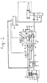
- an evaporating-pressure regulating system comprising a first reducing device 1 known per se, a heater/ evaporator 2 and a second reducing device 3.
- the liquid fuel supplied through the inlet conduit 4 to the first reducing device 1 and under variable pressure, is partly evaporated there and is supplied to the heater/evaporator 2 through the reducing device 1, comprising a valve 6 controlled by a diaphragm 5 and a spring 7, where the fuel evaporates completely and is heated.
- the gas is supplied to the second reducing device 3.
- a first inlet conduit 9 which is connected with a first chamber 13 of the second reducing device by a valve 12 controlled by a diaphragm 10 and a spring 11.
- a second inlet conduit 14, opening in the first chamber 13 through an adjustable restriction 15 and a third inlet conduit 16, opening in a second chamber 23 through an adjustable restriction 19, are provided.
- These second and third inlet conduits 14 and 16 respectively are connected to the first inlet conduit 9 by a valve 21 controlled by a fuel control member 8.
- Said second chamber 23 is defined on the one hand by the rear side of the diaphragm 10 controlling valve 12 and on the other hand by a baffle 24 provided with a restriction with fixed surface area 17, a nozzle 18 and a safety valve 25.
- a chamber 23' is provided, in which a valve 27, being controlled by the fuel control member 8, acts on the nozzle 18.
- said chamber 23' is connected with the first chamber 13 by a conduit 30 comprising an adjustable restriction 20.
- the outlet conduit 31 of the first chamber 13 can be provided with an adjustable restriction 22 between the first chamber and the feed point of the user.
- the device functions as follows: By the combustion engine an under pressure is created in the outlet 31 of the second reducing device 3 and so in the first chamber 13. By this diaphragm 10 will open the valve 12 against the pressure of spring 11, by which the gas, being under constant pressure supplied from the first reducing device 1 and from the heater/evaporator 2 can flow into the first chamber 13 and at opening 32 into the inlet 33 of the combustion engine, as is known per se. At the same time independently of the underpressure in the first chamber 13 always a quantity of gas determined by the adjustable restriction 15 flows through the second inlet conduit 14 into the first chamber 13. This quantity functions as fuel for the idling of the combustion engine.
- a constant quantity of gas flows through the third inlet conduit 16 into the second chamber 23 and to the first chamber through a fixed restriction 17, an adjustable restriction assembly 18, 27 and an adjustable restriction 20.
- Said quantity of gas is also used for preparing the idling mixture of the combustion engine, but can also provide a pressure amplifying system.
- a considerable underpressure must be supplied to the diaphragm 10.
- the discharge of gas from the second chamber 23 is regulated such that if more fuel is required, said discharge is decreased, by which the pressure in the second chamber 23 increases and the diaphragm 10 also thereby further opens valve 12. This load-depending regulation of the pressure in the second chamber 23 can be realised in several ways.
- Fig. 1 it comprises a fixed restriction 17 and a variable restriction assembly 18, 27.
- actuating valve 27 By moving actuating valve 27 more to nozzle 18, the pressure in the second chamber 23 and so the force on the diaphragm 10 will increase and with it the free area of valve 12 will increase.
- the actuating valve 27 is controlled by a fuel control member 8.
- this fuel control member 8 data relating to the number of revolutions, the load, the temperature, the position of the throttle valve in the inlet manifold, the amount of detrimental substances, oxygen in the exhaust gases, etc, are processed to an optimum position of the actuating valve 27.
- the device can also be combined with a device as described in EP-A-0118938 (priority date 4.2.83, filing date 6.2.84) and the fuel actuating member can give signals to a temperature control member described therein and not shown here.
- the fuel control member 8 is also connected to valve 21. By this the valve 21 can, if the combustion engine rotates faster than the idling speed but does not deliver any power, more or less be closed, by which the quantity of fuel required for idling is not supplied and the amplifying effect, as described above, is terminated, such that no or very little fuel is supplied to the engine.
- the adjustable restriction 20 being provided in the conduit 30 between the first and second chamber, functions to trim the second reducing device 3 to the subject engine.
- the safety valve 25 is provided for blowing off the pressure through the conduit 30, if said pressure in the second chamber 23 increases too much.
- a conduit 35 can be provided being connected with the first reducing device 1 through a restriction 34, by which the supply pressure of the gas to the second reducing device 3 can be influenced.
- the pressure of the gas supplied to the second reducing device 3 can be further controlled, in which the influence thereof on the pressure in the first chamber 13 of the second reducing device 3 is small because of the restriction 34 and the fuel member 8 is able to relatively simply overrule the pressure prevailing in the first chamber 13.
- a stable pressure regulating system is provided being adapted to the whether or not linear characteristic of the combustion engine.
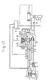
- FIG. 2 another preferred embodiment of the invention is shown, which only differs from the Fig. 1 embodiment by another load-dependent regulating of the pressure in the second chamber 23, which is obtained as follows.
- the free flow out area of nozzle 18 is determined by the position of a second diaphragm 26.
- This diaphragm 26 may or may not be influenced by a spring 36 at the other side, and is influenced by the pressure in a conduit 37, the reference pressure, through a damping device.
- the damping device comprises in the shown embodiment a baffle 38 being placed between the second diaphragm 26 and the conduit 37, and being provided with a fixed restriction 28 and a nozzle 40, of which the free flow out area is influenced by a third diaphragm 29 influenced by spring 39, said diaphragm 29 being influenced at the other side by the pressure in the second chamber 23.
- the overpressure in the second chamber 23, determining the amplifying function of the device, is dependent on the position of the second diaphragm 26. Apart from the damping device the position of the diaphragm is determined by the interaction of the gas arriving from restriction 19 and the pressure in the conduit 37. As the first is constant, the pressure in conduit 37 ultimately determines the position of the diaphragm.
- the underpressure in the first chamber 13 will increase at a determined quantity suctioned air if the air filter clogs, but by the underpressure in the conduit 37 the amplifying function of the gas arriving from the third inlet conduit 16 decreases because the second diaphragm further opens the nozzle.
- a further embodiment of the invention is shown, corresponding with the embodiment shown in Fig. 2 without spring 36, but at which the second diaphragm comprises two mutually connected first and second membrane parts 42 and 43 respectively.
- the diaphragm 43 has a larger surface area then diaphragm 42.
- a space is defined, which is divided in a chamber 46 faced to the third diaphragm 29 and a chamber 47 faced to the first diaphragm 10 by a baffle 44.
- Said baffle 44 comprises additionally to an opening for connecting both diaphragm parts 42 and 43 and sealed relatively to the chambers 46 and 47, a restriction 45.
- the chamber 46 is on the one hand connected to the fuel control member by the conduit 51, whilst on the other hand being connected to the inlet delivery sensing point 49 in the inlet of the engine through a restriction 48 and the conduit 50. Because of the difference in surface area between the diaphragms 42 and 43 each pressure difference at both sides of the larger diaphragm 43 corresponds in the state of equilibrium with a larger pressure difference at both sides of the diaphragm 42. By this diaphragm system the pressure difference of the delivery sensing is amplified and inverted, by which the pressure in chamber 23' increases at increasing air delivery. The places for sensing the delivery (here by pressure difference sensing between 37 and 49) and for the introduction of gas into the inlet manifold at opening 32 are separated. This allows to optimally size the venturi for the function of measuring the air consumption of the engine, at which no account has to be taken of the gas which also flows through, as happens at conventional devices.
- the introduction point of the gas can be chosen to lie downstream of a compressor or below the throttle valve of a combustion engine if the inlet delivery sensing connections are positioned at the same side of the compressor, or throttle valve respectively.
Landscapes
- Engineering & Computer Science (AREA)
- Chemical & Material Sciences (AREA)
- Combustion & Propulsion (AREA)
- Mechanical Engineering (AREA)
- General Engineering & Computer Science (AREA)
- Oil, Petroleum & Natural Gas (AREA)
- Physics & Mathematics (AREA)
- Chemical Kinetics & Catalysis (AREA)
- General Chemical & Material Sciences (AREA)
- Fluid Mechanics (AREA)
- General Physics & Mathematics (AREA)
- Automation & Control Theory (AREA)
- Power Engineering (AREA)
- Output Control And Ontrol Of Special Type Engine (AREA)
- Vehicle Body Suspensions (AREA)
- Control Of Fluid Pressure (AREA)
- Fluid-Pressure Circuits (AREA)
Claims (11)
Priority Applications (1)
| Application Number | Priority Date | Filing Date | Title |
|---|---|---|---|
| AT84200173T ATE27988T1 (de) | 1983-02-04 | 1984-02-06 | Druckregelvorrichtung. |
Applications Claiming Priority (2)
| Application Number | Priority Date | Filing Date | Title |
|---|---|---|---|
| NL8300438 | 1983-02-04 | ||
| NL8300438A NL8300438A (nl) | 1983-02-04 | 1983-02-04 | Drukregelsysteem. |
Publications (2)
| Publication Number | Publication Date |
|---|---|
| EP0118937A1 EP0118937A1 (de) | 1984-09-19 |
| EP0118937B1 true EP0118937B1 (de) | 1987-06-24 |
Family
ID=19841357
Family Applications (1)
| Application Number | Title | Priority Date | Filing Date |
|---|---|---|---|
| EP84200173A Expired EP0118937B1 (de) | 1983-02-04 | 1984-02-06 | Druckregelvorrichtung |
Country Status (6)
| Country | Link |
|---|---|
| US (1) | US4526155A (de) |
| EP (1) | EP0118937B1 (de) |
| AT (1) | ATE27988T1 (de) |
| CA (1) | CA1212281A (de) |
| DE (1) | DE3464403D1 (de) |
| NL (1) | NL8300438A (de) |
Families Citing this family (13)
| Publication number | Priority date | Publication date | Assignee | Title |
|---|---|---|---|---|
| US4638783A (en) * | 1985-04-12 | 1987-01-27 | Dresser Industries, Inc. | Carburetion system for engines |
| DE3532367A1 (de) * | 1985-09-11 | 1987-03-19 | Gulde Regelarmaturen Gmbh & Co | Pneumatischer regler |
| US4813394A (en) * | 1986-06-03 | 1989-03-21 | St Clair Christie C | Carburetion systems |
| US5345918A (en) * | 1992-07-10 | 1994-09-13 | Gas Research Institute | Fuel system and constant gas pressure governor for a single-cylinder, four-stroke cycle engine |
| US5377647A (en) * | 1993-10-25 | 1995-01-03 | Jones; James M. | Fuel blending system for highly compressed gases |
| RU2118688C1 (ru) * | 1996-07-09 | 1998-09-10 | Республиканский центр научно-технического творчества учащихся Министерства народного образования Кабардино-Балкарской Республики | Система питания газового двигателя внутреннего сгорания |
| IT1306411B1 (it) * | 1998-12-30 | 2001-06-06 | Poliauto Di P Parietti & C S N | Apparato per la alimentazione di gas di petrolio liquefatto amotori a scoppio, comprendente un vaporizzatore isobarico e, a valle |
| DE10063273A1 (de) | 2000-12-19 | 2002-07-04 | Bosch Gmbh Robert | Überdruckerzeugungsvorrichtung und Ventil |
| US20090142725A1 (en) * | 2007-12-03 | 2009-06-04 | Paul Bryant | Dental matrix band |
| BR112013004647B1 (pt) * | 2010-08-27 | 2020-10-06 | Volvo Truck Corporation | Disposição de motor compreendendo um circuito de recuperação de calor |
| FR2999657B1 (fr) * | 2012-12-13 | 2015-01-23 | Klever Energy Europ | Systeme moteur a explosion alimente en gaz et appareil comportant un tel systeme tel qu'un groupe electrogene ou une motopompe |
| JP6161568B2 (ja) * | 2014-04-23 | 2017-07-12 | 本田技研工業株式会社 | バイフューエルエンジン |
| EP2952728A1 (de) * | 2014-06-05 | 2015-12-09 | Klever Energy Europe | Mit Gas betriebenes Verbrennungsmotorsystem, und ein solches System umfassendes Gerät, wie etwa ein Stromaggregat oder eine Motorpumpe |
Family Cites Families (13)
| Publication number | Priority date | Publication date | Assignee | Title |
|---|---|---|---|---|
| FR848603A (fr) * | 1938-02-11 | 1939-11-03 | Ig Farbenindustrie Ag | Dispositif pour introduire des gaz moteurs comprimés ou liquéfies dans un moteur à combustion interne à alimentation mélangée |
| US2962366A (en) * | 1957-11-15 | 1960-11-29 | E N N A M N V | Device for feeding a combustion motor with liquified petroleum gas |
| US2896599A (en) * | 1958-05-19 | 1959-07-28 | Ensign Carburetor Company | Gaseous fuel feed systems, with automatic starting and idling control, for internal combustion engines |
| CH431190A (de) * | 1965-02-02 | 1967-02-28 | Sulzer Ag | Verfahren zum Betrieb einer Kraftanlage mit einer Dieselbrennkraftmaschine mit flüssigem Brennstoff und mit Gas sowie Anlage zur Ausübung des Verfahrens |
| DE1910095A1 (de) * | 1968-03-06 | 1969-09-25 | Robertshaw Controls Co | Stroemungsmittel-Regeleinrichtung |
| US3540419A (en) * | 1968-10-01 | 1970-11-17 | Borg Warner | Supplemental fuel system |
| DE2361358A1 (de) * | 1973-12-10 | 1975-06-19 | Messer Griesheim Gmbh | Regeleinrichtung, insbesondere fuer eine fluessiggasanlage fuer verbrennungsmotoren |
| IT1099007B (it) * | 1978-07-21 | 1985-09-18 | Parietti Pietro | Regolatore di pressione per gas combustibili,particolarmente per motori a combustione interna |
| JPS56146044A (en) * | 1980-04-15 | 1981-11-13 | Toyota Motor Corp | Improving device for starting property of lpg engine |
| HU187333B (en) * | 1980-04-30 | 1985-12-28 | Yves Irvoas | Throttling device for internal combustion engine |
| US4352677A (en) * | 1980-10-14 | 1982-10-05 | Jones James S | Regulator for gas and air mixture |
| NL8101284A (nl) * | 1981-03-17 | 1982-10-18 | Hendrik Meine Kooy | Verdamper- drukregelaar. |
| CA1192973A (en) * | 1981-05-01 | 1985-09-03 | Colin G. Young | Gaseous fuel carburetion |
-
1983
- 1983-02-04 NL NL8300438A patent/NL8300438A/nl not_active Application Discontinuation
-
1984
- 1984-02-06 US US06/577,110 patent/US4526155A/en not_active Expired - Fee Related
- 1984-02-06 DE DE8484200173T patent/DE3464403D1/de not_active Expired
- 1984-02-06 EP EP84200173A patent/EP0118937B1/de not_active Expired
- 1984-02-06 AT AT84200173T patent/ATE27988T1/de not_active IP Right Cessation
- 1984-02-06 CA CA000446792A patent/CA1212281A/en not_active Expired
Also Published As
| Publication number | Publication date |
|---|---|
| EP0118937A1 (de) | 1984-09-19 |
| US4526155A (en) | 1985-07-02 |
| NL8300438A (nl) | 1984-09-03 |
| ATE27988T1 (de) | 1987-07-15 |
| DE3464403D1 (en) | 1987-07-30 |
| CA1212281A (en) | 1986-10-07 |
Similar Documents
| Publication | Publication Date | Title |
|---|---|---|
| US4526155A (en) | Pressure regulating system | |
| US4228773A (en) | Device to activate an adjusting member in dependence on load | |
| US4356802A (en) | Valve system for regulating the idling speed of Otto engines, particularly automobile engines | |
| US4813394A (en) | Carburetion systems | |
| EP0084723B1 (de) | Ladedruckregelung mit Höhenkorrektur | |
| US5002705A (en) | Carburetor including an idling adjustment system | |
| US4096839A (en) | Internal combustion engine air-fuel ratio control system utilizing oxygen sensor | |
| US4520785A (en) | Gaseous fuel supply and control system for an internal combustion engine | |
| US4205636A (en) | Apparatus for controlling the air fuel mixture of an internal combustion engine | |
| SE407837B (sv) | Regleringssystem for atercirkulation av avgaser i en forbrenningsmotor | |
| US4190026A (en) | Automobile speed control method and system | |
| US4765303A (en) | Gaseous fuel charge forming device for internal combustion engines | |
| US4352677A (en) | Regulator for gas and air mixture | |
| US3386710A (en) | Fuel system | |
| US4170971A (en) | Pneumatic pressure control valve assembly | |
| US4183372A (en) | Altitude compensation valve assembly | |
| US3930479A (en) | Fuel metering device for externally ignited internal combustion engines with compression of the air-fuel mixture | |
| US3577964A (en) | Control apparatus | |
| GB908629A (en) | Fuel control for gas turbine engines | |
| US4359433A (en) | Constant-pressure carburetor | |
| US4445475A (en) | Engine idling speed control systems | |
| US4222237A (en) | Exhaust gas purifying apparatus for internal combustion engine | |
| US4282840A (en) | Internal combustion engine with altitude compensation device | |
| GB1107681A (en) | Combustion engine fuel control | |
| US4077208A (en) | Secondary air supply control device |
Legal Events
| Date | Code | Title | Description |
|---|---|---|---|
| PUAI | Public reference made under article 153(3) epc to a published international application that has entered the european phase |
Free format text: ORIGINAL CODE: 0009012 |
|
| AK | Designated contracting states |
Designated state(s): AT BE CH DE FR GB IT LI LU NL SE |
|
| 17P | Request for examination filed |
Effective date: 19841023 |
|
| GRAA | (expected) grant |
Free format text: ORIGINAL CODE: 0009210 |
|
| AK | Designated contracting states |
Kind code of ref document: B1 Designated state(s): AT BE CH DE FR GB IT LI LU NL SE |
|
| REF | Corresponds to: |
Ref document number: 27988 Country of ref document: AT Date of ref document: 19870715 Kind code of ref document: T |
|
| ITF | It: translation for a ep patent filed | ||
| REF | Corresponds to: |
Ref document number: 3464403 Country of ref document: DE Date of ref document: 19870730 |
|
| ET | Fr: translation filed | ||
| PLBE | No opposition filed within time limit |
Free format text: ORIGINAL CODE: 0009261 |
|
| STAA | Information on the status of an ep patent application or granted ep patent |
Free format text: STATUS: NO OPPOSITION FILED WITHIN TIME LIMIT |
|
| 26N | No opposition filed | ||
| ITTA | It: last paid annual fee | ||
| PGFP | Annual fee paid to national office [announced via postgrant information from national office to epo] |
Ref country code: FR Payment date: 19911223 Year of fee payment: 9 |
|
| PGFP | Annual fee paid to national office [announced via postgrant information from national office to epo] |
Ref country code: GB Payment date: 19920127 Year of fee payment: 9 |
|
| PGFP | Annual fee paid to national office [announced via postgrant information from national office to epo] |
Ref country code: AT Payment date: 19920212 Year of fee payment: 9 |
|
| PGFP | Annual fee paid to national office [announced via postgrant information from national office to epo] |
Ref country code: CH Payment date: 19920217 Year of fee payment: 9 |
|
| PGFP | Annual fee paid to national office [announced via postgrant information from national office to epo] |
Ref country code: NL Payment date: 19920229 Year of fee payment: 9 |
|
| PGFP | Annual fee paid to national office [announced via postgrant information from national office to epo] |
Ref country code: DE Payment date: 19920331 Year of fee payment: 9 |
|
| PGFP | Annual fee paid to national office [announced via postgrant information from national office to epo] |
Ref country code: BE Payment date: 19920403 Year of fee payment: 9 |
|
| PGFP | Annual fee paid to national office [announced via postgrant information from national office to epo] |
Ref country code: LU Payment date: 19920416 Year of fee payment: 9 |
|
| PGFP | Annual fee paid to national office [announced via postgrant information from national office to epo] |
Ref country code: SE Payment date: 19920525 Year of fee payment: 9 |
|
| EPTA | Lu: last paid annual fee | ||
| PG25 | Lapsed in a contracting state [announced via postgrant information from national office to epo] |
Ref country code: LU Free format text: LAPSE BECAUSE OF NON-PAYMENT OF DUE FEES Effective date: 19930206 Ref country code: GB Effective date: 19930206 Ref country code: AT Effective date: 19930206 |
|
| PG25 | Lapsed in a contracting state [announced via postgrant information from national office to epo] |
Ref country code: SE Effective date: 19930207 |
|
| PG25 | Lapsed in a contracting state [announced via postgrant information from national office to epo] |
Ref country code: LI Effective date: 19930228 Ref country code: CH Effective date: 19930228 Ref country code: BE Effective date: 19930228 |
|
| BERE | Be: lapsed |
Owner name: VIALLE B.V. Effective date: 19930228 |
|
| PG25 | Lapsed in a contracting state [announced via postgrant information from national office to epo] |
Ref country code: NL Effective date: 19930901 |
|
| GBPC | Gb: european patent ceased through non-payment of renewal fee |
Effective date: 19930206 |
|
| NLV4 | Nl: lapsed or anulled due to non-payment of the annual fee | ||
| PG25 | Lapsed in a contracting state [announced via postgrant information from national office to epo] |
Ref country code: FR Effective date: 19931029 |
|
| REG | Reference to a national code |
Ref country code: CH Ref legal event code: PL |
|
| PG25 | Lapsed in a contracting state [announced via postgrant information from national office to epo] |
Ref country code: DE Effective date: 19931103 |
|
| REG | Reference to a national code |
Ref country code: FR Ref legal event code: ST |
|
| EUG | Se: european patent has lapsed |
Ref document number: 84200173.7 Effective date: 19930912 |