EP0118939A1 - Groupe de laminoirs à faible encombrement avec des cylindres supportés d'un côté et laminoir constitué par de tels groupes - Google Patents
Groupe de laminoirs à faible encombrement avec des cylindres supportés d'un côté et laminoir constitué par de tels groupes Download PDFInfo
- Publication number
- EP0118939A1 EP0118939A1 EP84200176A EP84200176A EP0118939A1 EP 0118939 A1 EP0118939 A1 EP 0118939A1 EP 84200176 A EP84200176 A EP 84200176A EP 84200176 A EP84200176 A EP 84200176A EP 0118939 A1 EP0118939 A1 EP 0118939A1
- Authority
- EP
- European Patent Office
- Prior art keywords
- supercompact
- units
- rolling
- rolls
- rolling group
- Prior art date
- Legal status (The legal status is an assumption and is not a legal conclusion. Google has not performed a legal analysis and makes no representation as to the accuracy of the status listed.)
- Granted
Links
- 238000005096 rolling process Methods 0.000 title claims abstract description 58
- 230000005540 biological transmission Effects 0.000 claims abstract description 16
- 230000033001 locomotion Effects 0.000 claims description 17
- 230000009467 reduction Effects 0.000 claims description 8
- 238000011144 upstream manufacturing Methods 0.000 claims description 4
- 238000012423 maintenance Methods 0.000 description 11
- 238000010276 construction Methods 0.000 description 4
- 230000009471 action Effects 0.000 description 2
- 230000000694 effects Effects 0.000 description 2
- 238000006073 displacement reaction Methods 0.000 description 1
- 238000009434 installation Methods 0.000 description 1
- 230000007246 mechanism Effects 0.000 description 1
- 230000001105 regulatory effect Effects 0.000 description 1
- 238000010008 shearing Methods 0.000 description 1
Images

Classifications
-
- B—PERFORMING OPERATIONS; TRANSPORTING
- B21—MECHANICAL METAL-WORKING WITHOUT ESSENTIALLY REMOVING MATERIAL; PUNCHING METAL
- B21B—ROLLING OF METAL
- B21B35/00—Drives for metal-rolling mills, e.g. hydraulic drives
- B21B35/02—Drives for metal-rolling mills, e.g. hydraulic drives for continuously-operating mills
-
- B—PERFORMING OPERATIONS; TRANSPORTING
- B21—MECHANICAL METAL-WORKING WITHOUT ESSENTIALLY REMOVING MATERIAL; PUNCHING METAL
- B21B—ROLLING OF METAL
- B21B13/00—Metal-rolling stands, i.e. an assembly composed of a stand frame, rolls, and accessories
- B21B13/005—Cantilevered roll stands
-
- B—PERFORMING OPERATIONS; TRANSPORTING
- B21—MECHANICAL METAL-WORKING WITHOUT ESSENTIALLY REMOVING MATERIAL; PUNCHING METAL
- B21B—ROLLING OF METAL
- B21B31/00—Rolling stand structures; Mounting, adjusting, or interchanging rolls, roll mountings, or stand frames
- B21B31/16—Adjusting or positioning rolls
- B21B31/20—Adjusting or positioning rolls by moving rolls perpendicularly to roll axis
- B21B31/22—Adjusting or positioning rolls by moving rolls perpendicularly to roll axis mechanically, e.g. by thrust blocks, inserts for removal
- B21B31/26—Adjusting eccentrically-mounted roll bearings
Definitions
- This invention concerns a supercompact rolling group.
- the invention concerns a rolling group with rolls supported at one end which has a conformation and mutual arrangement of the horizontal and vertical rolling units such as to make possible a considerable reduction of the overall sizes of the whole rolling group and also a better functional nature of the group as compared to known lay-outs.
- the invention also concerns a rolling line which comprises one or more groups formed in this manner.
- Such groups in their turn can include one or more rolling units, which should be understood as being an assemblage formed substantially by a carrying casing, or portion of a casing, which holds a set of rolls with related means providing support and direct movement.
- patent FR 1.456.709 is known and discloses a rolling mill which comprises several units with rolls supported at one end, the units being arranged on a common frame and inclined at 45° with alternate orientations.
- This cited patent is mainly intended to enable the rolls to be adjusted and driven in an improved manner and also to facilitate withdrawal of the rolls for maintenance.
- Patent FR 1.465.519 is also known and discloses a substantially analogous solution, the rolls of the units being inclined at 45°, the units themselves being arranged alternately, and the motion being transmitted to parallel shafts that drive the two groups of units, as in the patent cited previously.
- Patent DE-OS-2.243.749 discloses an embodiment like that of the patent cited above.
- Another purpose of the invention is to provide a rolling group which includes auxiliary devices to carry out operations that have hitherto been performed by separate devices, which, as they are separate, are subject to many shortcomings and problems of coordination, linking and control or maintenance.
- the supercompact lay-out of the units in the rolling group of the invention is made possible by assigning to the individual units forming the group a suitable conformation which enables not only the overall sizes to be reduced but also the desired cooperation to be maintained.
- vertical and horizontal units we mean units of which the rolls are disposed with their axes substantially vertical and horizontal respectively.
- any suitable alternation of horizontal and vertical units can be arranged.
- the units can be positioned alternately vertically and horizontally, or there can be several consecutive units oriented in the same way as each other.
- each motor is positioned with its axis substantially parallel to the axis of the unit which it drives.
- a train of cylindrical gears can be employed for each unit since there is no necessity to transmit motion on axes which are not parallel.
- the bevel gear pairs used in the known cited embodiments are therefore eliminated.
- the invention covers the possibility of assembling within the group auxiliary means such as shears, loop-forming means, etc.
- these auxiliary means make it possible to obtain, owing to the invention, a coordinated relationship and control and a maintenance which would otherwise be impossible.
- the outcome is a better use of the space available, better coordination of functions and lower maintenance costs.
- the units in a group which have rolls of the same diameter comprise roll-bearing headstocks that can be interchanged with each other and be withdrawn speedily for replacement and/or maintenance.
- the invention also envisages the possibility of the modular construction of the rolling group.
- the invention is therefore embodied with a supercompact rolling group with rolls supported at one end, which comprises vertical and horizontal units arranged alternately or as necessary, and in which each unit is driven by an independent motor through a transmission on parallel axes.
- the invention is also embodied with a rolling line which comprises at least one supercompact rolling group constituted in such a way.
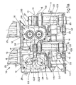
- a supercompact rolling group 10 has in the examples shown two vertical units 11 and one horizontal unit 12.
- the group 10 of the invention could, however, include any required number of units however they may be oriented.
- the various parts which form the unit 111 are, in fact, also to be found in the other units with a like function and relative collocation.
- a casing 14 having a box-like, substantially L-shaped form encloses a transmission group 15.
- the casing 14 can also be included as an independent element on its own or else be envisaged as being integrally joined to the casings of the other units so as to form one single framework for the group 10.
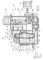
- the'transmission group 15 comprises a shaft 30 for each roll 18.
- Each shaft 30 has on itself a toothed wheel or pinion 31 which meshes with a pinion 32.
- the pinions 32 mesh with each other, only one of the pinions 32 receiving motion from a motor 25 through a train of gears 34.
- the contrarotating pinions 32 transmit the motion to the respective pinions 31 and thence through the shafts 30 to the rolls 18, which therefore rotate in the opposite direction to each other.
- the pinions 31 do not mesh with each other and therefore the distance between the centres of the rolls 18 can be regulated, a thing which otherwise would be impossible.
- An adjustment bush 33 which supports both ends of the shaft 30 is envisaged for each shaft 30 so as to perform the adjustment.
- the shaft 30 is fitted off-centre in relation to the adjustment bush 33, so that a rotation of the adjustment bush 33, of which the axis 133 is stationary, causes a displacement of the axis 130 of the relative shaft 30.
- the shafts 30 with the adjustment bushes 33, the rolls 18 and a carrying element 19 constitute a headstock 17 bearing rolls.
- the carrying element 19 comprises an upper plate 119 secured to the casing 14 with screws or other equivalent means. If the screws are removed, the roll-bearing headstock 17 can be withdrawn in one piece very easily.
- the headstocks 17 with rolls 18 of the same diameter can be interchanged advantageously, and a speedy replacement is made possible in this way for adjustment and/or maintenance purposes.
- the casings 14 of neighbouring vertical units 11 are connected with a union means 20, which can be envisaged as being an element on its own or as forming one block with the casing 14 of one of the neighbouring units 11.
- the horizontal 12 and vertical 11 units in their turn comprise suitable means 120 for reciprocal union, such as flanged or angled elements or elements of another kind.
- the union means are an integral part of that structure.
- the special L-shaped conformation of the units .11-12 has the effect that in correspondence with a substantially concave portion 21 delimited by the casing 14 and by the rolls 18 (on their left in Fig.1a) there can be positioned an elongated portion 16 of a neighbouring unit 12-11 having a different orientation.
- Fig.1a also shows a possible positioning of shears 22, here flying shears, in correspondence with the concave portion 21.
- the flying shears 22 have two rotors 122 with blades 222.
- the flying shears 22 can be withdrawn advantageously, being fitted to a carrying element 19 like the carrying elements 19 of the headstocks 17.
- the shears 22 can get their motion from a motor 23 that activates a unit, a horizontal unit 12 in our example, with its axis parallel to the axes of the rotors 122, by means of a train of cylindrical gears; or else an independent motor 24 can be envisaged for driving the shears 22 separately.
- Each vertical unit 11 gets its motion from a motor 25 having a vertical axis.
- the kinematic mechanisms 34 for transmission of motion from the motors 23-25 to the transmission groups 15 of the individual units are of a known type with cylindrical gear wheels.
- This transmission can have advantageously epicyclic reduction gears 123 and 125 for each motor 23-25 respectively.
- the lay-out of the units 11-12 which is made possible by their special L-shaped conformation, enables the distance between centres of rolls 18 of neighbouring units to be about the same as, or even less than, twice the diameter of the rolls 18 themselves, the distance in question being that between two consecutive units having orientations different from each other, namely between a horizontal unit and a vertical unit.
- a guide, or inlet may perhaps be employed between two consecutive units having the same orientation so as to guide the rolled sections and prevent them from being bent, depending on the type of rolled section being processed.
- Fig.1a shows a guide 26 located upstream from the flying shears 22, the guide 26 being required in that position to prevent dangerous deflections of the rolled sections during shearing.
- Fig.2 shows part of a rolling line having groups according to the invention.
- Loop-forming means 27 are located between successive groups 110-210.
- the function of the loop-forming means 27,as is known, is to prevent the creation of a pulling action on the rolled section, for such an action could have an unfavourable effect on the rolling process.
- loop-forming means 27 are connected directly to the neighbouring groups 110-210. This obviates the need to provide appropriate supporting means.
- the loop-forming means 27 according to the invention offer constructional simplification as compared to known solutions.
- Known loop-forming means consist generally of two fixed idler rolls and one roll substantially able to move crosswise to the direction of rolling.
- the function of one of the fixed rolls is carried out by the rolling roll 118 immediately upstream from the loop-forming means 27.
- a fixed idler roll 28 is located at the outlet end of the loop-forming means 27.
- a movable roll 29 can move substantially crosswise to the rolling axis 13 between positions 29A and 29B. In the latter position 29B the roll 29 displaces the rolled section to form a loop 113.
- shears 22 can be incorporated in one or more groups as in Fig.1a, and a variable number of loop-forming means 27 can be comprised, to suit the specific requirements.
- the number and sequence of the units 11-12 belonging to one group can be varied.
Landscapes
- Engineering & Computer Science (AREA)
- Mechanical Engineering (AREA)
- Metal Rolling (AREA)
- Secondary Cells (AREA)
- Press Drives And Press Lines (AREA)
- Crushing And Grinding (AREA)
- Rollers For Roller Conveyors For Transfer (AREA)
- Tires In General (AREA)
Priority Applications (1)
| Application Number | Priority Date | Filing Date | Title |
|---|---|---|---|
| AT84200176T ATE24425T1 (de) | 1983-02-25 | 1984-02-08 | Superkompakte walzgruppe mit an einem ende gelagerten walzrollen und walzlinie mit so gestalteten walzgruppen. |
Applications Claiming Priority (2)
| Application Number | Priority Date | Filing Date | Title |
|---|---|---|---|
| IT83336/83A IT1175058B (it) | 1983-02-25 | 1983-02-25 | Blocco di laminazione supercompatto con rulli a sbalzo e linea di laminazione comprendente blocchi cosi' formati |
| IT8333683 | 1983-02-25 |
Publications (2)
| Publication Number | Publication Date |
|---|---|
| EP0118939A1 true EP0118939A1 (fr) | 1984-09-19 |
| EP0118939B1 EP0118939B1 (fr) | 1986-12-30 |
Family
ID=11320324
Family Applications (1)
| Application Number | Title | Priority Date | Filing Date |
|---|---|---|---|
| EP84200176A Expired EP0118939B1 (fr) | 1983-02-25 | 1984-02-08 | Groupe de laminoirs à faible encombrement avec des cylindres supportés d'un côté et laminoir constitué par de tels groupes |
Country Status (6)
| Country | Link |
|---|---|
| US (1) | US4744234A (fr) |
| EP (1) | EP0118939B1 (fr) |
| AT (1) | ATE24425T1 (fr) |
| DE (1) | DE3461751D1 (fr) |
| ES (1) | ES8507018A1 (fr) |
| IT (1) | IT1175058B (fr) |
Cited By (4)
| Publication number | Priority date | Publication date | Assignee | Title |
|---|---|---|---|---|
| EP0366921A1 (fr) * | 1988-10-18 | 1990-05-09 | DANIELI & C. OFFICINE MECCANICHE S.p.A. | Dispositif pour l'échange d'équipement d'un ensemble intégral de cages de laminoir composées de paires de cylindres alternés et montés en porte-à-faux |
| EP0780168A1 (fr) * | 1995-12-22 | 1997-06-25 | DANIELI & C. OFFICINE MECCANICHE S.p.A. | Block de laminoir compact |
| EP0824045A3 (fr) * | 1996-07-18 | 1998-05-06 | Sms Schloemann-Siemag Aktiengesellschaft | Douille palier excentrique pour arbre de rouleau |
| KR101129885B1 (ko) * | 2003-06-27 | 2012-03-26 | 알카텔-루센트 유에스에이 인코포레이티드 | 통신 장비, 정보 송신 장비 및 정보 수신 장비 |
Families Citing this family (7)
| Publication number | Priority date | Publication date | Assignee | Title |
|---|---|---|---|---|
| AU596030B2 (en) * | 1987-10-30 | 1990-04-12 | Morgan Construction Company | Sizing mill and method of rolling a round bar material |
| DE59102051D1 (de) * | 1990-05-04 | 1994-08-04 | Schloemann Siemag Ag | Kombinierte Feinstahl- und Drahtstrasse. |
| CA2138319C (fr) * | 1993-12-22 | 1998-08-25 | Terence M. Shore | Laminoir monobloc en une ligne |
| US5595083A (en) * | 1994-08-01 | 1997-01-21 | Morgan Construction Company | Modular rolling mill |
| RU2203750C2 (ru) * | 2001-02-21 | 2003-05-10 | Открытое акционерное общество "Северсталь" | Способ эксплуатации подшипниковых узлов рабочих валков прокатного стана |
| US7191629B1 (en) | 2006-04-13 | 2007-03-20 | Morgan Construction Company | Modular rolling mill |
| US7523632B2 (en) * | 2007-02-15 | 2009-04-28 | Morgan Construction Company | Modular rolling mill |
Citations (4)
| Publication number | Priority date | Publication date | Assignee | Title |
|---|---|---|---|---|
| FR1456709A (fr) * | 1964-08-24 | 1966-07-08 | Morgan Construction Co | Laminoir |
| FR1465519A (fr) * | 1965-03-09 | 1967-01-13 | Wtz Feikeramischen Ind | Laminoir-finisseur à cylindres inclinés à 45deg. montés en porte-à-faux |
| DE2243749A1 (de) * | 1971-09-10 | 1973-03-22 | Pomini Farrel Spa | Kontinuierliche vorwalzstrasse |
| FR2294770A1 (fr) * | 1974-12-18 | 1976-07-16 | Pomini Farrel Spa | Perfectionnements aux laminoirs degrossisseurs continus |
Family Cites Families (6)
| Publication number | Priority date | Publication date | Assignee | Title |
|---|---|---|---|---|
| US1858788A (en) * | 1925-08-08 | 1932-05-17 | Rohn Wilhelm Julius Paul | Rolling mill |
| DE634752C (de) * | 1934-02-19 | 1936-09-03 | Fried Krupp Grusonwerk Akt Ges | Drahtwalzenstrasse, bestehend aus mehreren hintereinanderliegenden Walzensaetzen |
| US3538726A (en) * | 1968-01-16 | 1970-11-10 | Westinghouse Electric Corp | Method and apparatus for controlling the crop shear of a hot strip mill |
| FR2403839A1 (fr) * | 1977-09-26 | 1979-04-20 | Secim | Procede de regulation de l'epaisseur d'un produit plat en cours de laminage et installation correspondante |
| SE432069B (sv) * | 1979-10-23 | 1984-03-19 | Strandell Per Olof | Duovalspar |
| US4366694A (en) * | 1980-09-17 | 1983-01-04 | Morgan Construction Company | Compact rolling mill |
-
1983
- 1983-02-25 IT IT83336/83A patent/IT1175058B/it active
-
1984
- 1984-02-08 AT AT84200176T patent/ATE24425T1/de not_active IP Right Cessation
- 1984-02-08 DE DE8484200176T patent/DE3461751D1/de not_active Expired
- 1984-02-08 EP EP84200176A patent/EP0118939B1/fr not_active Expired
- 1984-02-16 ES ES529770A patent/ES8507018A1/es not_active Expired
-
1986
- 1986-02-24 US US06/834,106 patent/US4744234A/en not_active Expired - Lifetime
Patent Citations (4)
| Publication number | Priority date | Publication date | Assignee | Title |
|---|---|---|---|---|
| FR1456709A (fr) * | 1964-08-24 | 1966-07-08 | Morgan Construction Co | Laminoir |
| FR1465519A (fr) * | 1965-03-09 | 1967-01-13 | Wtz Feikeramischen Ind | Laminoir-finisseur à cylindres inclinés à 45deg. montés en porte-à-faux |
| DE2243749A1 (de) * | 1971-09-10 | 1973-03-22 | Pomini Farrel Spa | Kontinuierliche vorwalzstrasse |
| FR2294770A1 (fr) * | 1974-12-18 | 1976-07-16 | Pomini Farrel Spa | Perfectionnements aux laminoirs degrossisseurs continus |
Cited By (5)
| Publication number | Priority date | Publication date | Assignee | Title |
|---|---|---|---|---|
| EP0366921A1 (fr) * | 1988-10-18 | 1990-05-09 | DANIELI & C. OFFICINE MECCANICHE S.p.A. | Dispositif pour l'échange d'équipement d'un ensemble intégral de cages de laminoir composées de paires de cylindres alternés et montés en porte-à-faux |
| EP0780168A1 (fr) * | 1995-12-22 | 1997-06-25 | DANIELI & C. OFFICINE MECCANICHE S.p.A. | Block de laminoir compact |
| US5771733A (en) * | 1995-12-22 | 1998-06-30 | Daniele & C. Officine Meccaniche S.P.A. | Compact rolling block |
| EP0824045A3 (fr) * | 1996-07-18 | 1998-05-06 | Sms Schloemann-Siemag Aktiengesellschaft | Douille palier excentrique pour arbre de rouleau |
| KR101129885B1 (ko) * | 2003-06-27 | 2012-03-26 | 알카텔-루센트 유에스에이 인코포레이티드 | 통신 장비, 정보 송신 장비 및 정보 수신 장비 |
Also Published As
| Publication number | Publication date |
|---|---|
| EP0118939B1 (fr) | 1986-12-30 |
| ES529770A0 (es) | 1985-09-01 |
| IT1175058B (it) | 1987-07-01 |
| IT8383336A0 (it) | 1983-02-25 |
| ES8507018A1 (es) | 1985-09-01 |
| ATE24425T1 (de) | 1987-01-15 |
| DE3461751D1 (en) | 1987-02-05 |
| US4744234A (en) | 1988-05-17 |
Similar Documents
| Publication | Publication Date | Title |
|---|---|---|
| US4744234A (en) | Supercompact rolling group with rolls supported at one end, and a rolling line comprising groups thus formed | |
| EP2216107A1 (fr) | Système d'entraînement pour un laminoir, notamment pour un laminoir à pas de pèlerin à froid | |
| EP0707901A1 (fr) | Mécanisme à manivelle pour un laminoir à pas de pélerin à froid | |
| DE2822589A1 (de) | Vorrichtung zum ausgleichen der freien massenkraefte und -momente, insbesondere ii. ordnung, an einer hubkolben-brennkraftmaschine | |
| WO1986004009A1 (fr) | Robots industriels pour differentes applications | |
| EP0524711B1 (fr) | Laminoir à pas de pélerin à froid comportant une cage de laminoir mobile en va-et-vient | |
| US3016772A (en) | Drive assembly for metal working mill | |
| EP0933145B1 (fr) | Système d'engrenages à plusieurs rapports optionnels | |
| EP0121063B1 (fr) | Entraînement en rotation réglable sans jeu d'au moins un arbre principal pour manipulateurs | |
| DE19621585A1 (de) | Anordnung beim Antrieb einer Breitstreckwalze | |
| EP0581497B1 (fr) | Laminoir comportant un train finisseur en bloc avec possibilité d'ajustage de la vitesse de rotation | |
| US1954525A (en) | Wire straightening | |
| US4325245A (en) | Rolling mill stand | |
| US6161412A (en) | Multi-strand finishing block | |
| DE1285972B (de) | Richtwalzen-Antrieb fuer Blech-Richtmaschinen | |
| DE2328051A1 (de) | Vorrichtung fuer den vergleich der dynamischen unwucht eines werkstuecks mit einer dynamischen bezugsunwucht | |
| EP0332597B1 (fr) | Laminoir à fil en forme de bloc | |
| EP0840037A2 (fr) | Réducteur de vitesse ou motoréducteur | |
| RU2056957C1 (ru) | Прокатный стан | |
| DE3214412A1 (de) | Walzgeruest | |
| JPH0539769Y2 (fr) | ||
| US4158253A (en) | Simplified yarn coiler | |
| US2036101A (en) | Continuous rolling mill | |
| SU1028442A1 (ru) | Летучие ножницы | |
| DE712951C (de) | Fuer kontinuierliche Rohrreduzierwalzwerke bestimmtes Universalwalzwerk |
Legal Events
| Date | Code | Title | Description |
|---|---|---|---|
| PUAI | Public reference made under article 153(3) epc to a published international application that has entered the european phase |
Free format text: ORIGINAL CODE: 0009012 |
|
| AK | Designated contracting states |
Designated state(s): AT BE CH DE FR GB LI LU NL SE |
|
| 17P | Request for examination filed |
Effective date: 19850227 |
|
| GRAA | (expected) grant |
Free format text: ORIGINAL CODE: 0009210 |
|
| AK | Designated contracting states |
Kind code of ref document: B1 Designated state(s): AT BE CH DE FR GB LI LU NL SE |
|
| REF | Corresponds to: |
Ref document number: 24425 Country of ref document: AT Date of ref document: 19870115 Kind code of ref document: T |
|
| REF | Corresponds to: |
Ref document number: 3461751 Country of ref document: DE Date of ref document: 19870205 |
|
| ET | Fr: translation filed | ||
| PLBE | No opposition filed within time limit |
Free format text: ORIGINAL CODE: 0009261 |
|
| STAA | Information on the status of an ep patent application or granted ep patent |
Free format text: STATUS: NO OPPOSITION FILED WITHIN TIME LIMIT |
|
| 26N | No opposition filed | ||
| EPTA | Lu: last paid annual fee | ||
| EAL | Se: european patent in force in sweden |
Ref document number: 84200176.0 |
|
| REG | Reference to a national code |
Ref country code: GB Ref legal event code: IF02 |
|
| PGFP | Annual fee paid to national office [announced via postgrant information from national office to epo] |
Ref country code: AT Payment date: 20030121 Year of fee payment: 20 |
|
| PGFP | Annual fee paid to national office [announced via postgrant information from national office to epo] |
Ref country code: NL Payment date: 20030124 Year of fee payment: 20 Ref country code: GB Payment date: 20030124 Year of fee payment: 20 |
|
| PGFP | Annual fee paid to national office [announced via postgrant information from national office to epo] |
Ref country code: CH Payment date: 20030127 Year of fee payment: 20 Ref country code: BE Payment date: 20030127 Year of fee payment: 20 |
|
| PGFP | Annual fee paid to national office [announced via postgrant information from national office to epo] |
Ref country code: LU Payment date: 20030128 Year of fee payment: 20 |
|
| PGFP | Annual fee paid to national office [announced via postgrant information from national office to epo] |
Ref country code: SE Payment date: 20030129 Year of fee payment: 20 |
|
| PGFP | Annual fee paid to national office [announced via postgrant information from national office to epo] |
Ref country code: DE Payment date: 20030214 Year of fee payment: 20 |
|
| PGFP | Annual fee paid to national office [announced via postgrant information from national office to epo] |
Ref country code: FR Payment date: 20030224 Year of fee payment: 20 |
|
| PG25 | Lapsed in a contracting state [announced via postgrant information from national office to epo] |
Ref country code: LI Free format text: LAPSE BECAUSE OF EXPIRATION OF PROTECTION Effective date: 20040207 Ref country code: GB Free format text: LAPSE BECAUSE OF EXPIRATION OF PROTECTION Effective date: 20040207 Ref country code: CH Free format text: LAPSE BECAUSE OF EXPIRATION OF PROTECTION Effective date: 20040207 |
|
| PG25 | Lapsed in a contracting state [announced via postgrant information from national office to epo] |
Ref country code: NL Free format text: LAPSE BECAUSE OF EXPIRATION OF PROTECTION Effective date: 20040208 Ref country code: LU Free format text: LAPSE BECAUSE OF NON-PAYMENT OF DUE FEES Effective date: 20040208 Ref country code: AT Free format text: LAPSE BECAUSE OF EXPIRATION OF PROTECTION Effective date: 20040208 |
|
| REG | Reference to a national code |
Ref country code: CH Ref legal event code: PL |
|
| BE20 | Be: patent expired |
Owner name: *DANIELI & C. OFFICINE MECCANICHE S.P.A. Effective date: 20040208 |
|
| REG | Reference to a national code |
Ref country code: GB Ref legal event code: PE20 |
|
| EUG | Se: european patent has lapsed | ||
| NLV7 | Nl: ceased due to reaching the maximum lifetime of a patent |
Effective date: 20040208 |