EP0119048A1 - Filtre pour tube cathodique d'affichage et méthode de fabrication et de fixation au tube - Google Patents
Filtre pour tube cathodique d'affichage et méthode de fabrication et de fixation au tube Download PDFInfo
- Publication number
- EP0119048A1 EP0119048A1 EP84301430A EP84301430A EP0119048A1 EP 0119048 A1 EP0119048 A1 EP 0119048A1 EP 84301430 A EP84301430 A EP 84301430A EP 84301430 A EP84301430 A EP 84301430A EP 0119048 A1 EP0119048 A1 EP 0119048A1
- Authority
- EP
- European Patent Office
- Prior art keywords
- gasket
- peripheral
- filter
- elements
- faceplate
- Prior art date
- Legal status (The legal status is an assumption and is not a legal conclusion. Google has not performed a legal analysis and makes no representation as to the accuracy of the status listed.)
- Withdrawn
Links
Images


Classifications
-
- H—ELECTRICITY
- H01—ELECTRIC ELEMENTS
- H01J—ELECTRIC DISCHARGE TUBES OR DISCHARGE LAMPS
- H01J29/00—Details of cathode-ray tubes or of electron-beam tubes of the types covered by group H01J31/00
- H01J29/86—Vessels; Containers; Vacuum locks
- H01J29/89—Optical or photographic arrangements structurally combined or co-operating with the vessel
- H01J29/896—Anti-reflection means, e.g. eliminating glare due to ambient light
-
- H—ELECTRICITY
- H01—ELECTRIC ELEMENTS
- H01J—ELECTRIC DISCHARGE TUBES OR DISCHARGE LAMPS
- H01J2229/00—Details of cathode ray tubes or electron beam tubes
- H01J2229/89—Optical components associated with the vessel
- H01J2229/8913—Anti-reflection, anti-glare, viewing angle and contrast improving treatments or devices
- H01J2229/8922—Apparatus attached to vessel and not integral therewith
Definitions
- This invention relates to cathode ray tube (CRT) displays suitable for use under a wide range of ambient light conditions, such as in an aircraft cockpit, and accordingly requiring contrast enhancement filters forming an integral part of the cathode ray tube. More specifically, this invention relates to the manufacture of such filters and an apparatus and method for bonding them to the cathode ray tube face.
- CTR cathode ray tube
- Cathode ray 'tubes with contrast enhancement filters bonded to their display surface are well known in the prior art.
- home TV's often employ a protective glass faceplate bonded to the display surface some of which have neutral density filter characteristics, that is the ability to absorb, substantially equally, light over the entire visible spectrum.
- contrast enhancement filters must possess the capability of passing light in narrow bands of the visible light spectrum depending upon the light emissivity of the phosphors of the CRT.
- An example of filters of this type is disclosed in the present Applicants' U.S. Patent Specification No. 3,946,267.
- the present invention overcomes these and other problems discussed above by providing a unique method of manufacturing the contrast enhancement filter which provides great flexibility in filter pass band characteristic and by providing a unique apparatus and method for securing the filter to the CRT display face.
- Prior art techniques for securing a filter to the faceplate of a CRT include the spacing of the filter a short distance from the faceplate by means of a shim and the resulting peripheral gap is closed using an adhesive tape to form a liquid tight envelope.
- the bonding material such as a clear epoxy, is poured into the envelope and allowed to cure. This technique is cumbersome and time-consuming to perform and the spacing tolerance was not easily maintained. Furthermore, if care is not taken, the envelope leaks prior to curing, leaving unacceptable gaps and requiring rework.
- an elastomeric gasket provides a spacing bead but the filter assembly must be precisely aligned using a complex jig for maintaining the parts securely in position during the bonding operation.
- the present invention provides a unitary apparatus and method for assuring precise uniform filter/faceplate spacing and accomplishes assembly in very short time and with uniform predictable results and without the requirement for complex alignment jigs and jig set-up time.
- the present invention provides a method and apparatus for manufacturing a contrast enhancement filter assembly and for securing the same to the face of the CRT, each operation involving a peripheral flexible gasket of an elastomeric material which is deformable so that it may be stretched,out of shape in order to receive the rigid parts to be assembled and when the parts are in place, the gasket maintains them in a precisely spaced relation.
- a fill port is provided to fill the space between the parts with a bonding material.
- the elastomeric material may be compressed a known predetermined amount by means of a precisely machined rigid frame clamped about the peripheral gasket. The frame together with precision shims and replicas of the parts to be assembled may be used as a mould to manufacture the gasket.
- the overall assembly comprises the CRT faceplate and filter assembly 11 bonded to the faceplate with a suitable transparent epoxy material such as Eccogel 1265, a product of Emerson Cummings of Canton, Massachusetts, United States of America.
- the filter assembly comprises a sandwich of two sheets of optical quality glass and a filter of carefully controlled thickness of a suitable epoxy material, such as Eccogel 1265, which has been mixed with predetermined amounts of dyes to provide the required filter pass bands.
- the outer surface of the outer filter glass is provided with a conventional antireflective coating (ARC) whilst the surface of the other filter glass facing the CRT face is provided with a conventional transparent conductive coating to suppress electromagnetic emissions.
- An electrical conductor ribbon soldered to the edge of the conductive coating, provides an electrical connection to external apparatus.
- the entire peripheral surface of the viewing end of the CRT is coated with a conventional black elastomeric material, such as Dow Corning RTV-732 to mask any ambient light. It will be noted that although the CRT face is conventionally curved, the active filter material is of uniform thickness, thereby to provide uniform effectiveness across the entire face of the CRT.
- the apparatus and methods used to manufacture the filter assembly and to bond the same to the CRT faceplate will be described in detail hereinafter.
- the contrast enhancement filter is fabricated from two pieces of essentially transparent optical quality glass 22 and 23 which are spaced a known distance apart X, and then filled with an epoxy type material whose optical pass band matches the spectral wavelength of the light emitted by the phosphor or phosphors of the CRT.
- a conventional CRT phosphor P-43 is used as an example. As is known, this phosphor emits most of its light in the green portion of the visible spectrum at about 546 nanometers. Now the actual transmittance of the filter depends on the requirements of contrast and symbol brightness for the particular application. Therefore, there are significant advantages of a filter fabrication method which exhibits flexibility and ease of design.
- a narrow pass band filter may be formed at 546 nanometers by utilising a bluish green dye which passes light in the blue-green portion of the visible spectrum and combining that with a long wavelength band pass dye which appears to be yellow; when combined, these dyes form a narrow pass band 6.
- a dye formulation which will provide for an ease of filter design is desired, i.e. determining the concentrations of each dye.
- the absorption constant, ⁇ is given by:- where a ( ⁇ ) is a characteristic of the specific dye, constant for any particular ⁇ , and c is the dye concentration. So now:- Likewise,
- a mandrel 14 is designed which is to be used in the fabrication of an elastomeric gasket 15 ( Figure 2), that will capture the glass plates and maintain their required spacing x. Having determined the dimension x this value is predetermined by the spacing x shown in Figures 2 and 3.
- the mandrel 14 is designed with external raised bosses 60 which provide, in the resulting gasket, external lips 61 which will serve to capture the outer peripheries of the glass sheets 22 and 23.
- An external mould using techniques to be described below, is machined in which the mandrel 14 is to be placed. Provision is made in the mould to form a gasket filling spout 12, again as will be described.
- the mandrel 14 and mould are assembled with the top cover plate of the mould left off in order that the mould may be filled.
- One satisfactory elastomer for forming the gasket is General Electric RTVB 630. After mixing, the mixture is placed in a vacuum in order to outgas any air that may be trapped.
- the RTV is then poured into the mould, ensuring that all of the crevices are filled.
- the filled mould is set aside for about one half hour after which the cover plate is attached and the assembly placed in an oven and cured for two hours at about 80°C. After cooling, the mould is disassembled and the flexible, deformable gasket 15 is removed.
- the spacing bead 16 provides the predetermined fixed distance x and is, of course, equal to the gap 16 in the mandrel 14 shown in Figure 3, while the lips 61 capture and maintain the glass plates 22, 23 snugly abutting the bead 16.
- Two pieces of precisely cut glass 22 and 23 are inserted into the gasket as shown in Figures 2 and 4.
- One piece of glass preferably has a reflection reducing coating on the outer surface such as Optical Coating Laboratory's HEA coating.
- the other piece of glass preferably has a transparent conducting coating on the outer surface which has a resistivity less than 200 ohms/square inch (6.452 sq. cms.). This latter coating typically may be a conventional indium-tin-oxide, tin-oxide coating or any other well known conductive materials.
- a filter assembly is manufactured in the following manner.
- a suitable yellow dye that will provide the blue cutoff as shown by curve 20 in Figure 11 is Plasto Yellow MGSM manufactured by Tricon Colors of Elmwood Park, New Jersey.
- a suitable green pigment, i.e. one with the absorption characteristics shown by the curve 21 in Figure 11 and one that does not bleach under the influence of ultraviolet light is Gerisch Transparent Green manufactured by Gerisch Products of Torrence, California. The Gerisch Green concentrate is conventionally mixed on a paint mixer for example.
- the glass and gasket assembly ready for filling is shown in Figure 5.
- the gasket and glass assembly is also heated to assure good wetting by the epoxy mixture.
- the heated epoxy mixture is poured into the assembly through the pour spout 12 and the filled assembly is placed in an oven where it is cured for six hours at 80°C or longer if necessary.
- the assembly is removed from the oven, allowed to cool and the completed filter assembly 11 ( Figures 1 and 9) is then removed from the gasket 15 by again deforming and stretching as required.
- the filter assembly 11 as fabricated will have a small indentation around its periphery. This gap may be filled with the RTV-732 ( Figure 1) especially if the filter is not to be bonded to the CRT face for an extended period.
- the RTV will prevent any moisture from diffusing into the Eccogel layer.
- one of the glass sheets 22, 23 has its outer surface coated with a conventional transparent conductive material while the other glass sheet has its outer surface coated with a conventional antireflection material.
- Instruments, displays, and the like which are designed for use in aircraft cockpits not only require tight electrical tolerances but tight mechanical tolerances as well. The latter is influenced by the minimum amount of panel space and the usual lack of depth behind the panel.
- the CRT assembly which is a basic component of a cathodoluminescent display, must have the contrast enhancement filter 11 positioned precisely in all dimensions with respect to the CRT face.
- the present invention provides for the precise positioning of the filter in these dimensions with a minimum amount of labour during the bonding operation. Once the bonding material is cured, the filter will, of course, remain in that precise position.
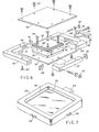
- the key to accomplishing the filter bonding task is the fabrication of a precision elastomeric gasket 50 shown in Figure 7 similar in many respects to the filter gasket 15 and similarly made.
- This gasket is fabricated in the following manner, reference being made to Figure 6.
- a replica 31 of the front of the particular CRT is machined from some appropriate material such as aluminium and a replica 32 of the filter assembly 11 is also fabricated.
- the filter assembly replica includes a raised boss 62 which will, in the completed gasket, provide an external lip 63 for capturing the filter assembly and maintaining it snugly against a bead 53 ( Figure 9). These two parts are then fastened to a baseplate 33 as by flat head screws 34.
- the filter replica is spaced a precise predetermined distance y from the CRT replica 31 by means of a shim or boss 35.
- the spacing y is defined by the particular display chassis design.
- the side walls 36, 37 and 38 of the gasket mould are machined in the configurations shown in Figure 6 from a suitable rigid material such as aluminium.
- the interior dimensions of these walls are precisely controlled because these parts are to be used not only as the side walls of the mould but also as the rigid clamping ring for the completed gasket 50 when it is used to bond the filter assembly 11 to the CRT face. Accordingly, when used to manufacture the gasket 30, the interior dimensions are lengthened slightly by adding the shims 39, 40 and 41 when the walls 36, 37 and 38 are joined together by means of bolts 42.
- the shims 39, 40 and 41 are removed, thereby slightly decreasing their interior dimensions so that when the frame members are screwed together the completed gasket embracing its associated parts will be compressed slightly, as will be described below, effecting a very tightly joined assembly during the actual bonding operation.
- the mould side walls 37, 38 and 39 are bolted together with shims 39, 40 and 41 inserted and the resulting frame secured to the base plate 33 as by screws 33' forming an annular channel between the frame and the already assembled members 31 and 32.
- the side wall 36 includes an opening 43 which, together with a plug 43', will form a filling spout 54 of the completed gasket.
- the plug 43 is secured to the side wall 36 by screws 44; openings 45 assure that no air is trapped in the spout neck upon filling the mould.
- Centrally located along the inner surface of the side walls 37 and 38 are cut-outs 48 which will form tabs 49 ( Figure 7) on the completed mould.
- the annular channel of the filter CRT bonding mould is completely filled with RTV-630, which has been premixed and outgassed as above, left to stand about thirty minutes to assure complete saturation and then the cover plate 46 is attached by means of screws 47, any excess RTVB being squeezed through holes 45.
- the filled mould is finally cured for two hours or so at 80°C. After cooling, the mould is disassembled and the resulting gasket 50 inspected and any flashing removed.
- the exterior lip 63 and interior surface bead 53 assure precisely establishment and maintenance of the spacing dimension y without the requirement for any complex jigs or other apparatus.
- the gasket is now completed and ready for use bonding the filter assembly 11 to the faceplate of the CRT.
- a filter assembly 11 is inserted into the internal groove 51 by deforming and stretching the peripheral elastomer gasket 50 about the filter assembly periphery as shown in Figure 4, resulting in the partially assembled gasket shown in Figure 7.
- the conductive coated side faces towards the rear, i.e. towards the bead 53.
- the gasket 50 with its inserted filter assembly 11 is laid on a flat surface with interior surface 52 up and the frame members 36, 37 and 38 loosely assembled by bolts 42, but without the shims 39, 40 and 41, are placed around the gasket and the bolts 42 tightened just enough that the frame members contact the outer surfaces of the gasket with the tabs 49 in their corresponding recesses 48 in the frame members.
- the CRT is now placed in the gasket 50 firmly pressed down so that its faceplate periphery snugly fits aginst the bead 53 and the gasket interior wall 52.
- the bolts 42 are now tightened down to an effective torque of about 12.5 inch pounds, a value which has been predetermined to provide a very tight compression seal between the elastomeric gasket 50 and its enclosed rigid parts.
- the completed assembly is now oriented to the position shown in Figure 8 on the work surface with the fill spout 54 uppermost for receiving the bonding material.
- the material for bonding the filter to the CRT is Eccogel 1265.
- thirty grams of Eccogel part A are mixed with thirty grams of Eccogel part B. In this case, there are no additives and the material is clear transparent.
- the mixture is then heated to 80°C in a vacuum oven to decrease the viscocity and to remove any entrapped air bubbles.
- the CRT assembly is also heated as before.
- the Eccogel is then poured into the bonding gasket 50 through the fill spout 54 until the latter is full.
- the filled assembly is placed in an oven heated to 80 0 c for a period of six hours or so for curing. It is then removed from the oven and allowed to cool, the bolts removed and the claim disassembled.
- the gasket 50 is then stripped from the assembly in one piece by deformation and stretching.
- the gasket 50 can be reused many times.
- there will be a small gap (Figure 1) around the periphery of the Eccogel between the faceplate and the filter assembly 11 which is filled with the black RTV-732 as the latter is applied to the entire external periphery of the faceplate filter assembly.
- the RTV prevents any ambient light from leaking in behind the filter.
- the apparatus and methods and procedures described above have a precise bond between the contrast enhancement filter 11 and the CRT faceplate which can be accomplished in a minimum amount of time with substantially no requirement for rework. It is also to be appreciated that in both cases the gaskets 15, 50 have a cross-sectional dimension such as to provide sufficient gasket body that no complex holding and aligning jigs are required as taught in the prior art thus saving tedious and costly set-up time.
Landscapes
- Vessels, Lead-In Wires, Accessory Apparatuses For Cathode-Ray Tubes (AREA)
- Manufacture Of Electron Tubes, Discharge Lamp Vessels, Lead-In Wires, And The Like (AREA)
- Devices For Indicating Variable Information By Combining Individual Elements (AREA)
Applications Claiming Priority (2)
| Application Number | Priority Date | Filing Date | Title |
|---|---|---|---|
| US47499583A | 1983-03-14 | 1983-03-14 | |
| US474995 | 1983-03-14 |
Publications (1)
| Publication Number | Publication Date |
|---|---|
| EP0119048A1 true EP0119048A1 (fr) | 1984-09-19 |
Family
ID=23885810
Family Applications (1)
| Application Number | Title | Priority Date | Filing Date |
|---|---|---|---|
| EP84301430A Withdrawn EP0119048A1 (fr) | 1983-03-14 | 1984-03-05 | Filtre pour tube cathodique d'affichage et méthode de fabrication et de fixation au tube |
Country Status (3)
| Country | Link |
|---|---|
| EP (1) | EP0119048A1 (fr) |
| JP (1) | JPS59169042A (fr) |
| IL (1) | IL71204A0 (fr) |
Cited By (3)
| Publication number | Priority date | Publication date | Assignee | Title |
|---|---|---|---|---|
| DE3629996A1 (de) * | 1986-09-03 | 1988-03-17 | Flachglas Ag | Vorsatzaggregat fuer die kathodenstrahlroehre von monitoren, fernsehapparaten und dergleichen |
| DE3643088A1 (de) * | 1986-12-17 | 1988-06-30 | Flabeg Gmbh | Fernseh-bildroehre mit verbundfrontscheibe |
| EP0616355A1 (fr) * | 1993-03-17 | 1994-09-21 | Koninklijke Philips Electronics N.V. | Dispositif d'affichage et tube à rayons cathodiques |
Families Citing this family (1)
| Publication number | Priority date | Publication date | Assignee | Title |
|---|---|---|---|---|
| JPH01195639A (ja) * | 1988-01-29 | 1989-08-07 | Matsushita Electric Ind Co Ltd | 投写用陰極線管 |
Citations (5)
| Publication number | Priority date | Publication date | Assignee | Title |
|---|---|---|---|---|
| FR1255147A (fr) * | 1960-03-18 | 1961-03-03 | Encadrement pour entourer et fixer le verre de protection d'un tube de télévision | |
| FR1335626A (fr) * | 1962-07-12 | 1963-08-23 | Le Cathoscope Francais | Procédés et dispositifs pour donner un aspect coloré aux écrans des tubes à rayons cathodiques oscillographiques et cinescopes |
| US3164672A (en) * | 1960-10-14 | 1965-01-05 | Owens Illinois Glass Co | Controlling implosions in cathode-ray and other tubes |
| FR2197232A1 (fr) * | 1972-08-24 | 1974-03-22 | Sony Corp | |
| GB2024092A (en) * | 1978-06-28 | 1980-01-09 | Sperry Rand Corp | Method of assembling a contrastenhanced display device |
-
1984
- 1984-02-15 JP JP59026924A patent/JPS59169042A/ja active Pending
- 1984-03-05 EP EP84301430A patent/EP0119048A1/fr not_active Withdrawn
- 1984-03-09 IL IL71204A patent/IL71204A0/xx unknown
Patent Citations (5)
| Publication number | Priority date | Publication date | Assignee | Title |
|---|---|---|---|---|
| FR1255147A (fr) * | 1960-03-18 | 1961-03-03 | Encadrement pour entourer et fixer le verre de protection d'un tube de télévision | |
| US3164672A (en) * | 1960-10-14 | 1965-01-05 | Owens Illinois Glass Co | Controlling implosions in cathode-ray and other tubes |
| FR1335626A (fr) * | 1962-07-12 | 1963-08-23 | Le Cathoscope Francais | Procédés et dispositifs pour donner un aspect coloré aux écrans des tubes à rayons cathodiques oscillographiques et cinescopes |
| FR2197232A1 (fr) * | 1972-08-24 | 1974-03-22 | Sony Corp | |
| GB2024092A (en) * | 1978-06-28 | 1980-01-09 | Sperry Rand Corp | Method of assembling a contrastenhanced display device |
Cited By (6)
| Publication number | Priority date | Publication date | Assignee | Title |
|---|---|---|---|---|
| DE3629996A1 (de) * | 1986-09-03 | 1988-03-17 | Flachglas Ag | Vorsatzaggregat fuer die kathodenstrahlroehre von monitoren, fernsehapparaten und dergleichen |
| US4804883A (en) * | 1986-09-03 | 1989-02-14 | Flachglass Aktiengesellschaft | Front attachment for CRT. E.G. for a monitor or video tube |
| DE3643088A1 (de) * | 1986-12-17 | 1988-06-30 | Flabeg Gmbh | Fernseh-bildroehre mit verbundfrontscheibe |
| US4926090A (en) * | 1986-12-17 | 1990-05-15 | Flabeg Gmbh | Television picture tube having a composite frontal pane |
| EP0616355A1 (fr) * | 1993-03-17 | 1994-09-21 | Koninklijke Philips Electronics N.V. | Dispositif d'affichage et tube à rayons cathodiques |
| BE1006922A3 (nl) * | 1993-03-17 | 1995-01-24 | Philips Electronics Nv | Beeldweergave-inrichting en kathodestraalbuis. |
Also Published As
| Publication number | Publication date |
|---|---|
| JPS59169042A (ja) | 1984-09-22 |
| IL71204A0 (en) | 1984-06-29 |
Similar Documents
| Publication | Publication Date | Title |
|---|---|---|
| US5446591A (en) | Lens mounting for use with liquid lens elements | |
| JPH0961829A (ja) | 液晶表示素子の製造方法 | |
| GB2343965A (en) | Liquid crystal display panel assembly | |
| DE69407216T2 (de) | Farbkathodenstrahlröhre | |
| EP0119048A1 (fr) | Filtre pour tube cathodique d'affichage et méthode de fabrication et de fixation au tube | |
| DE2926174C2 (fr) | ||
| DE69618702T2 (de) | Verfahren zur Herstellung einer Bildanzeigevorrichtung mit Flachschirm | |
| US5105290A (en) | Liquid crystal display device with an inlet sealant containing particles | |
| US4613786A (en) | Image intensifiers and method of producing same | |
| US4710820A (en) | Single layer optical coupler for projection TV CRT | |
| DE69402751T2 (de) | Anzeigevorrichtung und Kathodenstrahlröhre | |
| EP0113957A1 (fr) | Procédé pour la fabrication d'une structure de verre laminé | |
| DE2421255B2 (de) | Optische Korrekturlinse für ein Projektionssystem und Verfahren zu ihrer Herstellung | |
| JP3516103B2 (ja) | 液晶表示装置 | |
| CN1104807C (zh) | 透射型屏幕及其制造方法 | |
| US4544575A (en) | Method of making glass panels with selective radiation-blocking effect | |
| EP0528603A1 (fr) | Procédé de fabrication d'un dispositif d'affichage à cristal liquide | |
| KR0130367B1 (ko) | 브라운관의 형광면 구조 및 제조방법 | |
| JP2978110B2 (ja) | 液晶表示装置 | |
| JPH0420927A (ja) | カラーフイルタ基板およびそれを用いた液晶表示素子 | |
| KR20010017589A (ko) | 평면 브라운관의 안전유리 부착방법 | |
| JPH02210486A (ja) | カラー情報表示装置用フィルタ | |
| EP0875916A3 (fr) | Tube à rayons cathodiques couleur ayant au moins un type d'un film fluorescent constitué de particules fluorescentes ayant une couche sélective en longueur d'onde et procédé de fabrication | |
| KR950000823B1 (ko) | 투사형 텔리비젼용 음극선관 장치 | |
| EP0340924A2 (fr) | Procédé pour la mise en forme d'un écran |
Legal Events
| Date | Code | Title | Description |
|---|---|---|---|
| PUAI | Public reference made under article 153(3) epc to a published international application that has entered the european phase |
Free format text: ORIGINAL CODE: 0009012 |
|
| AK | Designated contracting states |
Designated state(s): DE FR GB IT |
|
| STAA | Information on the status of an ep patent application or granted ep patent |
Free format text: STATUS: THE APPLICATION IS DEEMED TO BE WITHDRAWN |
|
| 18D | Application deemed to be withdrawn |
Effective date: 19850521 |
|
| RIN1 | Information on inventor provided before grant (corrected) |
Inventor name: MAGGIO, STEPHEN CHRISTOPHER Inventor name: TRIMMIER, J. ROBERT |