EP0119074B1 - Schwimmer und Tiefenlot - Google Patents
Schwimmer und Tiefenlot Download PDFInfo
- Publication number
- EP0119074B1 EP0119074B1 EP84301590A EP84301590A EP0119074B1 EP 0119074 B1 EP0119074 B1 EP 0119074B1 EP 84301590 A EP84301590 A EP 84301590A EP 84301590 A EP84301590 A EP 84301590A EP 0119074 B1 EP0119074 B1 EP 0119074B1
- Authority
- EP
- European Patent Office
- Prior art keywords
- line
- float
- fishing
- fishing line
- hook
- Prior art date
- Legal status (The legal status is an assumption and is not a legal conclusion. Google has not performed a legal analysis and makes no representation as to the accuracy of the status listed.)
- Expired
Links
- XLYOFNOQVPJJNP-UHFFFAOYSA-N water Substances O XLYOFNOQVPJJNP-UHFFFAOYSA-N 0.000 claims abstract description 35
- 238000005188 flotation Methods 0.000 claims description 27
- 238000004804 winding Methods 0.000 claims description 6
- 230000005484 gravity Effects 0.000 claims description 4
- 238000000034 method Methods 0.000 claims description 4
- 239000012530 fluid Substances 0.000 description 7
- 238000005266 casting Methods 0.000 description 4
- 239000004793 Polystyrene Substances 0.000 description 3
- 238000010276 construction Methods 0.000 description 3
- 229920002223 polystyrene Polymers 0.000 description 3
- 238000004519 manufacturing process Methods 0.000 description 2
- 239000000463 material Substances 0.000 description 2
- 239000004033 plastic Substances 0.000 description 2
- 241000251468 Actinopterygii Species 0.000 description 1
- 239000011324 bead Substances 0.000 description 1
- 238000005260 corrosion Methods 0.000 description 1
- 230000007797 corrosion Effects 0.000 description 1
- 239000013078 crystal Substances 0.000 description 1
- 230000007423 decrease Effects 0.000 description 1
- 230000009977 dual effect Effects 0.000 description 1
- 230000000694 effects Effects 0.000 description 1
- 229920005669 high impact polystyrene Polymers 0.000 description 1
- 239000004797 high-impact polystyrene Substances 0.000 description 1
- 239000003562 lightweight material Substances 0.000 description 1
- 238000005259 measurement Methods 0.000 description 1
- 239000000203 mixture Substances 0.000 description 1
- 230000002093 peripheral effect Effects 0.000 description 1
- 238000009987 spinning Methods 0.000 description 1
- 238000003466 welding Methods 0.000 description 1
Images

Classifications
-
- A—HUMAN NECESSITIES
- A01—AGRICULTURE; FORESTRY; ANIMAL HUSBANDRY; HUNTING; TRAPPING; FISHING
- A01K—ANIMAL HUSBANDRY; AVICULTURE; APICULTURE; PISCICULTURE; FISHING; REARING OR BREEDING ANIMALS, NOT OTHERWISE PROVIDED FOR; NEW BREEDS OF ANIMALS
- A01K93/00—Floats for angling, with or without signalling devices
-
- A—HUMAN NECESSITIES
- A01—AGRICULTURE; FORESTRY; ANIMAL HUSBANDRY; HUNTING; TRAPPING; FISHING
- A01K—ANIMAL HUSBANDRY; AVICULTURE; APICULTURE; PISCICULTURE; FISHING; REARING OR BREEDING ANIMALS, NOT OTHERWISE PROVIDED FOR; NEW BREEDS OF ANIMALS
- A01K91/00—Lines
- A01K91/20—Line length or depth measuring devices
Definitions
- This invention relates to a float and depth gauge. More particularly, this invention relates to a fishing float and depth gauge.
- US-A-2077184 discloses a combination of a fishing float and a fishing line, said float having a light elongate floatation member, and at least one pair of receiving means on spaced-apart regions of the member each to define an aperture through which the fishing line is slidably received in enclosed relation.
- the floats which have been used are of the set-type or of the slip-type.
- the set-type of float is one which is usually fixed to a fishing line for use at shallow depths of water.
- One known set-type float has a body provided with a spring biased hook at one or both ends which can be drawn into a recess of the body in order to clamp a fishing line between the hook and body.
- Other known set-type floats are of similar construction. In each case, the float is fixed to the the line and is not intended to move during use. However, these floats usually have a short useful life due to corrosion and/or breakage of the moving parts. Further, these floats require complex manufacturing and assembling techniques. Also, when in use, the spring biased hooks can put an undesired crimp in a fishing line.
- a set float It is also impractical for a set float to be used for anything but shallow depths, for example, if a set float is set for the line to be (10 feet) 3,04 m or (15 feet) 4,57 m deep it would be virtually impossible to cast with a standard 5 1/2 foot or 6 foot spinning pole. Thus, a slip float must be used.
- Slip-type floats are generally formed of a float body with a central bore or passage.
- the fishing line is first threaded through the float body and, thereafter, one or more hooks and a sinker are applied to the end of the line.
- a float is able to slide along the fishing line until abutting a loop knot, a segment of rubber band or soft string, obstruction or the like in the line which acts as a stop past which the float will not pass.
- the line is usually cut at a point above the usual tackle and a rethreading of a new float made on the line. This is, of course, wasteful of time and fishing line.
- floats which can be removed from a line from time to time.
- a float can be made of two parts which are hinged together so as to sandwich a fishing line therebetween when closed.
- use has been made of interfitting ribs atthe ends of the two paths of the float in order to clamp the fishing line to the float.
- the floats have been made of two pieces which can dove-tail together in a slide fit relation so as to clamp onto a fishing line.
- the sinker and hook may well rest on the bottom in a slack manner rather than having the hook spaced above the bottom. Likewise, if the depth is greater than that estimated, the hook will be suspended far above the desired location.
- a combination of a fishing float, and a fishing line having the feature of claim 1.
- the flotation member may be of an elongated cylindrical or oblong shape and is preferably made of light-weight material such as plastic. In order to enhance the buoyancy of the float, the float is made hollow.
- the flat elements are disposed in opposed relation such that the aperture is completely enclosed in a peripheral manner.
- the elements may be resilient to permit passage of a fishing line therebetween in transverse relation. This permits a fishing line to be inserted into the aperture when placing the float on a fishing line. Likewise, the resilient nature of the elements permits the line to pass therebetween for removal of the float from the line.
- Each hook-shaped element of the float may also be provided with a transverse protruberance which projects into the plane of the adjacent element in order to retain a fishing line within the aperture defined by the elements.
- the float may also be provided with a securing means intermediate of the ends of the flotation member for securing a fishing line to the member in a fixed position.
- the fishing line used may be of monofilament construction, to which a sinker and one or more fish hooks may be affixed at one end.
- the fishing line is slid between the flat hook-shaped elements at one end of the float and then rotated 90° in order to snap into the aperture defined by these elements.
- the line is fitted into the aperture defined by the hook shaped elements at the opposite end of the float. At this time, the float, fishing hooks and sinker can then be cast.
- the tension in the fishing line is such as to clamp the line to the float so that the float, fishing hooks and sinker do not impede the casting operation.
- the tension in the line relative to the float decreases.
- the sinker is able to fall under gravity until reaching the bottom of the body of a water while the line slides through the float which is maintained on the surface of the water.
- the float becomes a measure of the depth of the water at that point.
- the line is retrieved while again imparting tension to the line in order to clamp the float to the line.
- a certain length is measured off from this point to establish the depth at which the fishing hook is to be placed for subsequent fishing operation.
- a rubber band, knot, or other type of tie is placed in the fishing line at this point and the remainder of the line is reeled in. Thereafter, the line is recast, and when the tie slides into abutment with the float, a fishing operation may begin. At this time, the fishing hook will be suspended from the float at a level above the bottom.
- the present invention also provides an apparatus for gauging the depth of a body of water, having the features of claim 10.
- the invention also provides a method of determining the depth of a fluid such as a body of water using an apparatus as described in the immediately preceding paragraph.
- This method comprises the steps of dropping the line, sinker and float onto the surface of the body of fluid in order to permit the sinker to fall under gravity until reaching a bottom under the body of fluid.
- the line is retrieved while imparting tension to the line to clamp the float to the line such that the latter is locked on the line at a location indicative of the depth of the body of fluid.
- the location of the clamped float is marked on the line as a measure of the depth of the body of fluid.
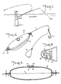
- the float 10 is adapted to be removably secured to a fishing line 11 to which one or more hooks 12 and a sinker 13 have been secured at one end in a conventional manner.
- the line 11 may be of any suitable type such as a synthetic mono-filament.
- the hook 12 and sinker 13 may be of any conventional structure.
- the float 10 includes a flotation member 14 of hollow elongated cylindrical shape and receiving means 15 mounted on opposite ends of the flotation member 14 for slidably receiving the fishing line 11 in a freely enclosed relation.
- the flotation member 14 is made into halves 14' which are secured together along a plane of symmetry X (see Figure 4). Each half 14' is substantially identical to the other half 14'.
- the flotation member 14 is of relatively thin- walled thickness so as to be light-weight, particularly for buoyancy.
- the float 10 may be of various lengths, for example 0,91 m (three inches), 1,21 m (four inches) and 1,82 m (six inches).
- the float 10 may be of light weight such as 6,52 g (0.23 ounces) for a 0,91 mm (three inch) float.
- the float 10 is made of any suitable material, such as polystyrene, or may be made of various mixtures of polystyrene, such as a high impact polystyrene and a crystal polystyrene.
- Each receiving means 15 is formed by a pair of first hook shaped elements 16, 17 which are disposed in opposed relation so as to define an aperture 18 therebetween (see Figure 3).
- the hook shaped elements 16, 17 are integral with and extend from the flotation member 14 on opposite sides of the plane of symmetry X.
- each element 16, 17 carries a transverse protuberance 19 which projects into the plane of the opposed elements.
- each protuberance 19 substantially fills the gap between the free end of an element 16, 17 and the base of the elements 16, 17.
- the outermost ends of the hook shaped elements 16, 17 have a chamfer 20 to define a V-shaped recess therebetween.
- the float 10 also has a securing means 21 on the flotation member at a point intermediate the ends of the member 14 for securing the fishing line 11 thereto.
- this securing means includes a central post 22 which protrudes from one half 14' of the flotation member 14 and a cap 23 on the post 22 which defines a recess 24 with the post 22 and the flotation member 14.
- the post 22 is integrally secured to the flotation member half 14' for example by thermo-welding while the cap 23 is integrally cast with the post 22.
- the cap 23 contacts the member 14 peripherally such that the recess 24 is closed.
- the recess 24 is also sized to retain one or more windings of the fishing line 11.
- the filament line 11 is of relatively large diameter only one winding need be accommodated within the recess 24 in order to secure the float 10 to the line 11 in fixed manner.
- the fishing line 11 is of relatively small diameter, two windings of the line may be accommodated within the recess 24 in order to affix the float 10 to the line 11.
- the float 10 In order to utilize the float 10 as a depth gauge the float is secured to the fishing line 11, for example, after the hook 12 and sinker 13 have been secured in place. At this time, the fishing line 11 is slid between the resilient hook shaped elements 16, 17 at one end of the flotation member 14' in a transverse manner (parallel to the plane of symmetry X). The line 11 is then passed about the free ends of the elements 16, 17 into a plane perpendicular to the plane of symmetry X. In this position, the line is free to slide within the elongated aperture 18 formed by the elements 16, 17. A similar operation is then carried out to insert the line within the aperture 18 defined by the elements 16,17 at the opposite end of the flotation member 14 (see Figure 2).
- the float 10, line 11, hook 12 and sinker 13 can be cast onto the surface of a body of water 25.
- the tension in the line 11 is sufficient to clamp the float 10 to the line 11. This may well be due to the aerodynamic shape of the float 10, the light weight of the float 10 and the frictional forces between the line 11 and float 10. In any event, the float 10 remains in place until arriving at the desired location on the water 25.
- the sinker 13 upon dropping onto the surface of the water 25, the sinker 13 falls under gravity until reaching the bottom 26. At the same time, the line 11 slides through the apertures 18 at the ends of the float 10 while the float 10 remains on the surface of the water 25. In this respect, upon reaching the surface of the water 25, the line relaxes relative to the float 10 so that the float 10 permits the line 11 to slide therethrough.
- the line 11 again is tensioned due to the weight of the suspended sinker 13 so that the float 10 is again clamped to the line 11 (see Figure 7).
- the location of the float 10 on the line 11 is thus indicative of the depth of the body of water 25.
- a suitable means such as a tie, rubber band or the like is placed in the line 11 at a point spaced from the float to establish the depth at which the hook 12 is to be located for fishing. That is, this operation permits the fishing hook 12 to be located at a fixed point above the bottom 26 of the water 25.
- the fishing line 11 is again recast with the float 10 again being held on the line.
- the line 11 slides through the float 10 up to the location of the tie (see Figure 9). That is, upon reaching the desired location, the sinker 13 will be suspended above the bottom 26 while the fishing hook 12 is located at the desired fishing height.
- the float 10 can again be used as a depth gauge to measure the depth of a different location in the body of water.
- any tie which has been formed on the fishing line can be readily removed.
- the line 11 is simply snapped under the cap 23. In this respect, the inherent resilience of the cap 23 is sufficient to hold the float 10 on the line 11. If further securement is needed, the line 11 may be wound about the post 22 as indicated in Figure 8 to form one or more windings.
- removal can be carried out in a relatively simple manner.
- a length of the line 11 leading from the float 10 may be doubled over on itself (see Figure 8) and slid into the aperture 18 in a manner as above. This results in a loop being formed in the line, which loop extends to one side of the float 10. The loop may then be drawn through the aperture 18 so that the float 10 is released from the line 11 at this end.
- a similar operation is then carried out at the opposite end of the float 10 so that the float is completely removed.
- the invention thus provides a float which provides a dual function of acting as a float which can be cast without impeding the casting operation as well as acting as a depth gauge for measuring the depth of a body of water for fluid.
- the invention further provides a float of light-weight construction which can be readily removed from a fishing line without having to destroy the line.
- the invention further provides a float which can be easily mounted on a fishing line for use in different depths of water.
- the float Since the float has no moving parts, there is no danger of debris or grit clogging the float. Further, the apertures provided by the receiving means at each end of the float are exposed so that each can be readily cleaned should any material lodge therein. Still further, because of the absence of moving parts, such as springs within the float, fabrication can be carried out at low cost and the float may have a long useful life. Finally, the float does not impart any undesirable crimp in the fishing line.
Landscapes
- Life Sciences & Earth Sciences (AREA)
- Environmental Sciences (AREA)
- Animal Husbandry (AREA)
- Biodiversity & Conservation Biology (AREA)
- Level Indicators Using A Float (AREA)
Claims (11)
Priority Applications (1)
| Application Number | Priority Date | Filing Date | Title |
|---|---|---|---|
| AT84301590T ATE36930T1 (de) | 1983-03-10 | 1984-03-09 | Schwimmer und tiefenlot. |
Applications Claiming Priority (2)
| Application Number | Priority Date | Filing Date | Title |
|---|---|---|---|
| US47417683A | 1983-03-10 | 1983-03-10 | |
| US474176 | 1983-03-10 |
Publications (2)
| Publication Number | Publication Date |
|---|---|
| EP0119074A1 EP0119074A1 (de) | 1984-09-19 |
| EP0119074B1 true EP0119074B1 (de) | 1988-09-07 |
Family
ID=23882486
Family Applications (1)
| Application Number | Title | Priority Date | Filing Date |
|---|---|---|---|
| EP84301590A Expired EP0119074B1 (de) | 1983-03-10 | 1984-03-09 | Schwimmer und Tiefenlot |
Country Status (5)
| Country | Link |
|---|---|
| EP (1) | EP0119074B1 (de) |
| JP (1) | JPS59196412A (de) |
| AT (1) | ATE36930T1 (de) |
| CA (1) | CA1219123A (de) |
| DE (1) | DE3473808D1 (de) |
Families Citing this family (10)
| Publication number | Priority date | Publication date | Assignee | Title |
|---|---|---|---|---|
| GB2227704B (en) * | 1989-02-03 | 1992-10-14 | Drennan Int | Fishing floats |
| FR2668891A1 (fr) * | 1990-11-08 | 1992-05-15 | Salina Eliane | Flotteurs par integration laterale pour peche a la ligne. |
| EP0519108A1 (de) * | 1991-06-20 | 1992-12-23 | Leonidas Mpizanis | Pose für Angelschnur |
| GB2305344A (en) * | 1995-09-21 | 1997-04-09 | William James Harmon | Fishing float |
| FR2808655A1 (fr) | 2000-05-09 | 2001-11-16 | Philippe Feret | Procede de peche a l'aide d'un cerf-volant |
| WO2007002617A2 (en) * | 2005-06-24 | 2007-01-04 | Dream Waters, Inc. | Reversibly disengaging slidable strike indicator, positioning system, and method of using same |
| US9010016B2 (en) | 2005-06-24 | 2015-04-21 | Dream Waters, Inc. | Reversibly disengaging slidable strike indicator, positioning system, and method of using same |
| GB2437237B (en) * | 2006-04-18 | 2010-12-29 | Nash Tackle Ltd | Marker float |
| CN107041347B (zh) * | 2017-04-01 | 2022-07-01 | 吕天翼 | 海钓用鸭嘴夹浮漂及其快速测底、浮游海钓底层鱼的方法 |
| US11134664B2 (en) * | 2019-10-27 | 2021-10-05 | Steven C. James | Fishing tackle and method of use thereof |
Family Cites Families (6)
| Publication number | Priority date | Publication date | Assignee | Title |
|---|---|---|---|---|
| US1558928A (en) * | 1923-07-16 | 1925-10-27 | Martin J Schamerloh | Fishline bobber |
| US2077184A (en) * | 1935-10-25 | 1937-04-13 | Hermenegildo P Gonzales | Fishline float |
| US2322241A (en) * | 1941-03-24 | 1943-06-22 | Christian A Kurz | Fishing float |
| US2310030A (en) * | 1941-07-12 | 1943-02-02 | Edward H Kruse | Bobber for fish lines |
| DE1012491B (de) * | 1955-12-02 | 1957-07-18 | Liselotte Pfister Geb Siewerth | Schwimmer mit Tiefenlot fuer die Angelfischerei |
| DE1632977A1 (de) * | 1967-11-29 | 1972-05-18 | Willi Eggemann | Laufpose fuer die Grundangelei,die sich selbstaendig auf die Wassertiefe ein- und feststellt |
-
1984
- 1984-03-09 JP JP59044203A patent/JPS59196412A/ja active Pending
- 1984-03-09 DE DE8484301590T patent/DE3473808D1/de not_active Expired
- 1984-03-09 AT AT84301590T patent/ATE36930T1/de not_active IP Right Cessation
- 1984-03-09 EP EP84301590A patent/EP0119074B1/de not_active Expired
- 1984-03-09 CA CA000449230A patent/CA1219123A/en not_active Expired
Also Published As
| Publication number | Publication date |
|---|---|
| DE3473808D1 (en) | 1988-10-13 |
| ATE36930T1 (de) | 1988-09-15 |
| EP0119074A1 (de) | 1984-09-19 |
| JPS59196412A (ja) | 1984-11-07 |
| CA1219123A (en) | 1987-03-17 |
Similar Documents
| Publication | Publication Date | Title |
|---|---|---|
| CA1219123A (en) | Float and depth gauge | |
| US5526575A (en) | Fish measuring apparatus | |
| US4561205A (en) | Float and depth gauge | |
| EP0035996B1 (de) | Vorrichtung für den schwimmer einer wurfangel | |
| US4574515A (en) | Fishing bobber | |
| CA1105260A (en) | Bob for cast fishing | |
| US2824728A (en) | Aquarium aerator | |
| CA1234695A (en) | Fishing float | |
| US6581321B2 (en) | Jig and fishing system | |
| US4571874A (en) | Casting bobber with predetermined depth setting | |
| US6425200B1 (en) | Two-stage fishing bobber | |
| US3714923A (en) | Depth marker for a fish line | |
| US5613888A (en) | Fisherman's marker | |
| US3646684A (en) | Depth-finding device | |
| US6018903A (en) | Apparatus for transporting a fishing line | |
| US4672769A (en) | Adjustable fishing float | |
| US4831762A (en) | Fishing float | |
| US4195435A (en) | Float position adjustment apparatus for fishing line | |
| US7437851B2 (en) | Two-stage fishing bobber | |
| US6158160A (en) | Ice free fishing line signal device | |
| US5327672A (en) | Slip bobber for ice fishing | |
| CA2538427A1 (en) | Fishing float | |
| JP3000975U (ja) | 魚釣り用目印及び目印付き釣り糸 | |
| GB2305344A (en) | Fishing float | |
| US4883365A (en) | Device for measuring subsurface temperatures of liquid bodies, useful for determining optimum fishing locations |
Legal Events
| Date | Code | Title | Description |
|---|---|---|---|
| PUAI | Public reference made under article 153(3) epc to a published international application that has entered the european phase |
Free format text: ORIGINAL CODE: 0009012 |
|
| AK | Designated contracting states |
Designated state(s): AT CH DE FR GB IT LI NL SE |
|
| 17P | Request for examination filed |
Effective date: 19850312 |
|
| 17Q | First examination report despatched |
Effective date: 19860424 |
|
| GRAA | (expected) grant |
Free format text: ORIGINAL CODE: 0009210 |
|
| AK | Designated contracting states |
Kind code of ref document: B1 Designated state(s): AT CH DE FR GB IT LI NL SE |
|
| PG25 | Lapsed in a contracting state [announced via postgrant information from national office to epo] |
Ref country code: NL Effective date: 19880907 Ref country code: LI Effective date: 19880907 Ref country code: IT Free format text: LAPSE BECAUSE OF FAILURE TO SUBMIT A TRANSLATION OF THE DESCRIPTION OR TO PAY THE FEE WITHIN THE PRESCRIBED TIME-LIMIT;WARNING: LAPSES OF ITALIAN PATENTS WITH EFFECTIVE DATE BEFORE 2007 MAY HAVE OCCURRED AT ANY TIME BEFORE 2007. THE CORRECT EFFECTIVE DATE MAY BE DIFFERENT FROM THE ONE RECORDED. Effective date: 19880907 Ref country code: CH Effective date: 19880907 Ref country code: AT Effective date: 19880907 |
|
| REF | Corresponds to: |
Ref document number: 36930 Country of ref document: AT Date of ref document: 19880915 Kind code of ref document: T |
|
| REF | Corresponds to: |
Ref document number: 3473808 Country of ref document: DE Date of ref document: 19881013 |
|
| ET | Fr: translation filed | ||
| REG | Reference to a national code |
Ref country code: CH Ref legal event code: PL |
|
| NLV1 | Nl: lapsed or annulled due to failure to fulfill the requirements of art. 29p and 29m of the patents act | ||
| PLBE | No opposition filed within time limit |
Free format text: ORIGINAL CODE: 0009261 |
|
| STAA | Information on the status of an ep patent application or granted ep patent |
Free format text: STATUS: NO OPPOSITION FILED WITHIN TIME LIMIT |
|
| 26N | No opposition filed | ||
| PGFP | Annual fee paid to national office [announced via postgrant information from national office to epo] |
Ref country code: GB Payment date: 19910226 Year of fee payment: 8 |
|
| PGFP | Annual fee paid to national office [announced via postgrant information from national office to epo] |
Ref country code: SE Payment date: 19910320 Year of fee payment: 8 Ref country code: FR Payment date: 19910320 Year of fee payment: 8 |
|
| PGFP | Annual fee paid to national office [announced via postgrant information from national office to epo] |
Ref country code: DE Payment date: 19910402 Year of fee payment: 8 |
|
| PG25 | Lapsed in a contracting state [announced via postgrant information from national office to epo] |
Ref country code: GB Effective date: 19920309 |
|
| PG25 | Lapsed in a contracting state [announced via postgrant information from national office to epo] |
Ref country code: SE Effective date: 19920310 |
|
| GBPC | Gb: european patent ceased through non-payment of renewal fee | ||
| PG25 | Lapsed in a contracting state [announced via postgrant information from national office to epo] |
Ref country code: FR Effective date: 19921130 |
|
| PG25 | Lapsed in a contracting state [announced via postgrant information from national office to epo] |
Ref country code: DE Effective date: 19921201 |
|
| REG | Reference to a national code |
Ref country code: FR Ref legal event code: ST |
|
| EUG | Se: european patent has lapsed |
Ref document number: 84301590.0 Effective date: 19921005 |