EP0119227B1 - Versorgungsanlage für die luft- und raumfahrt - Google Patents
Versorgungsanlage für die luft- und raumfahrt Download PDFInfo
- Publication number
- EP0119227B1 EP0119227B1 EP83902889A EP83902889A EP0119227B1 EP 0119227 B1 EP0119227 B1 EP 0119227B1 EP 83902889 A EP83902889 A EP 83902889A EP 83902889 A EP83902889 A EP 83902889A EP 0119227 B1 EP0119227 B1 EP 0119227B1
- Authority
- EP
- European Patent Office
- Prior art keywords
- compressor
- air
- generator
- supply device
- space navigation
- Prior art date
- Legal status (The legal status is an assumption and is not a legal conclusion. Google has not performed a legal analysis and makes no representation as to the accuracy of the status listed.)
- Expired
Links
Images

Classifications
-
- F—MECHANICAL ENGINEERING; LIGHTING; HEATING; WEAPONS; BLASTING
- F02—COMBUSTION ENGINES; HOT-GAS OR COMBUSTION-PRODUCT ENGINE PLANTS
- F02B—INTERNAL-COMBUSTION PISTON ENGINES; COMBUSTION ENGINES IN GENERAL
- F02B63/00—Adaptations of engines for driving pumps, hand-held tools or electric generators; Portable combinations of engines with engine-driven devices
- F02B63/04—Adaptations of engines for driving pumps, hand-held tools or electric generators; Portable combinations of engines with engine-driven devices for electric generators
-
- B—PERFORMING OPERATIONS; TRANSPORTING
- B64—AIRCRAFT; AVIATION; COSMONAUTICS
- B64F—GROUND OR AIRCRAFT-CARRIER-DECK INSTALLATIONS SPECIALLY ADAPTED FOR USE IN CONNECTION WITH AIRCRAFT; DESIGNING, MANUFACTURING, ASSEMBLING, CLEANING, MAINTAINING OR REPAIRING AIRCRAFT, NOT OTHERWISE PROVIDED FOR; HANDLING, TRANSPORTING, TESTING OR INSPECTING AIRCRAFT COMPONENTS, NOT OTHERWISE PROVIDED FOR
- B64F1/00—Ground or aircraft-carrier-deck installations
- B64F1/34—Ground or aircraft-carrier-deck installations for starting propulsion plant
-
- F—MECHANICAL ENGINEERING; LIGHTING; HEATING; WEAPONS; BLASTING
- F02—COMBUSTION ENGINES; HOT-GAS OR COMBUSTION-PRODUCT ENGINE PLANTS
- F02B—INTERNAL-COMBUSTION PISTON ENGINES; COMBUSTION ENGINES IN GENERAL
- F02B63/00—Adaptations of engines for driving pumps, hand-held tools or electric generators; Portable combinations of engines with engine-driven devices
-
- F—MECHANICAL ENGINEERING; LIGHTING; HEATING; WEAPONS; BLASTING
- F02—COMBUSTION ENGINES; HOT-GAS OR COMBUSTION-PRODUCT ENGINE PLANTS
- F02B—INTERNAL-COMBUSTION PISTON ENGINES; COMBUSTION ENGINES IN GENERAL
- F02B3/00—Engines characterised by air compression and subsequent fuel addition
- F02B3/06—Engines characterised by air compression and subsequent fuel addition with compression ignition
-
- Y—GENERAL TAGGING OF NEW TECHNOLOGICAL DEVELOPMENTS; GENERAL TAGGING OF CROSS-SECTIONAL TECHNOLOGIES SPANNING OVER SEVERAL SECTIONS OF THE IPC; TECHNICAL SUBJECTS COVERED BY FORMER USPC CROSS-REFERENCE ART COLLECTIONS [XRACs] AND DIGESTS
- Y02—TECHNOLOGIES OR APPLICATIONS FOR MITIGATION OR ADAPTATION AGAINST CLIMATE CHANGE
- Y02T—CLIMATE CHANGE MITIGATION TECHNOLOGIES RELATED TO TRANSPORTATION
- Y02T50/00—Aeronautics or air transport
- Y02T50/80—Energy efficient operational measures, e.g. ground operations or mission management
Definitions
- the invention relates to an aerospace supply system for the optional provision of compressed air for use as starting air and optionally electrical energy, the compressed air being able to be generated by means of at least one compressor actuated by an internal combustion engine.
- a stationary aerospace supply system can be found, for example, in US-A-41 01 100.
- Compressed air and electrical energy are supplied to mobile units via supply lines, which are then released to supply an aircraft.
- the compressed air is generated using a screw compressor.
- This must be designed to be quite voluminous in order to provide the required mass throughput at the required pressure.
- the electrical energy itself is taken from the electrical supply network, which is then transformed into the required voltage or converted into the required frequency.
- Corresponding systems are structurally complex and therefore maintenance-intensive. For this reason, use, for example, at smaller airports flown by jet machines or at airfields in the Third World is difficult or impossible to use. For this reason, it is necessary for the jet aircraft to either have installed supply systems themselves or to carry mobile devices, which is disadvantageous solely for reasons of cost. But there is another disadvantage. If a corresponding starter device on board is defective, a replacement device must be flown in, otherwise the machine is stuck.
- FR-A-1 473 215 describes a mobile installation for generating electrical energy and compressed air.
- the motor is connected to the compressor and the generator via V-belts.
- the speed of the generator cannot be set independently of that of the compressor.
- the compressor itself is a piston compressor, the compressed air of which is neither oil nor pulsation-free. With a piston compressor, it is also not possible to generate the required amounts of starting air, unless you build the piston compressor in a size of about a family home. Then the system would no longer be mobile.
- a system corresponding to FR-A-1 473 215 is therefore not intended for the supply of machines in the aerospace industry. Rather, it is a common machine that z. B. is used in road works. It is also possible to shake concrete to the required extent using a suitable mobile machine.
- the object of the present invention is to provide a supply system of the type described above in such a way that it is possible to produce electrical energy and, if appropriate, compressed air economically to the required extent, the compressor ensuring a mass flow rate corresponding to the intended use and the compressed air being oil and pulsation-free .
- the engine is a diesel engine, by means of which a generator and optionally the compressor designed as a radial or axial compressor can be driven, the speed of the generator being adjustable independently of that of the compressor.
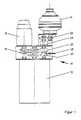
- a supply system 10 according to the invention is shown in a schematic representation, which essentially comprises a diesel engine 12, a compressor 14 and a generator 16.
- the output shaft of the diesel engine 12 operates on the one hand a continuously variable transmission in the form of a mechanical converter 18 according to the PIV principle and on the other hand a manual transmission 20 which is connected via a freewheel 22 to a powershift clutch 24 which in turn actuates the compressor 14 via a gear transmission 26.
- the gearbox can be replaced by another suitable gearbox.
- the powershift clutch 24 and the manual transmission 20 or a corresponding transmission can be interchanged.
- the mechanical converter 18, the output shaft of which actuates the generator 16 is now designed in such a way that a control unit, for example by hydraulic pressure on the disks, ensures that the frequency of the generator 16 is kept constant even when the speed of the diesel engine 12 changes.
- the mechanical converter 18 can also be replaced by a hydrostatic or hydrodynamic converter.
- the compressor 14 can optionally be switched on and by means of the clutch 24 at standstill and operation, namely when pulsation-free and oil-free compressed air is required.
- the speed of the motor 12 can be increased.
- the increase in the engine speed does not cause the frequency of the generator 16 to change, since in this case the transmission ratio of the transmission 18 is reduced accordingly. This continues until the compressor 14 has reached its nominal speed.
- the regulation or keeping the generator frequency constant is achieved by means of the engine speed controller, which is preferably designed electronically / electromechanically and also reacts to changes in the speed of the generator.
- FIG. 2 shows an alternative embodiment of a supply system 30 according to the invention, which likewise comprises a diesel engine 32, which is followed by a transfer case 34, preferably in the form of a gear transmission, the output shafts of which drive a generator 36 and a compressor 38.
- the compressor 38 is likewise a radial and / or axial compressor like the compressor 14 according to FIG. 1.
- the gear transmission is followed by a fluid coupling 40 in order to use a planetary gear 42 to transmit the power flow from the output shaft of the gear transmission 34 to enable the compressor 38.
- the speed of the compressor 38 can be controlled independently of the speed of the generator 36 by means of the fluid coupling, which works according to the Föttinger principle.
- the transfer case 34 can be followed by a continuously variable transmission, the output shaft of which is connected to the generator 36, so as to also set the speed of the generator independently of the speed of the compressor 38.
- the compressor 38 can optionally be switched on or off by means of the fluid coupling 40.
- starting air / on-board power supply systems are made available for the first time, which are compact and mobile and, in comparison with the conventional devices, have a considerably lower weight.
- a weight of approximately 1.5 tons is sufficient, whereas conventional starters operated with a diesel engine have a weight of 5 tons, with which, however, only compressed air can be generated.
- On-board power supply systems have the same weight.
Landscapes
- Engineering & Computer Science (AREA)
- Chemical & Material Sciences (AREA)
- Combustion & Propulsion (AREA)
- Mechanical Engineering (AREA)
- General Engineering & Computer Science (AREA)
- Aviation & Aerospace Engineering (AREA)
- Compressors, Vaccum Pumps And Other Relevant Systems (AREA)
- Control Of Vehicle Engines Or Engines For Specific Uses (AREA)
- Structures Of Non-Positive Displacement Pumps (AREA)
- Connection Of Motors, Electrical Generators, Mechanical Devices, And The Like (AREA)
- Control Of Transmission Device (AREA)
Description
- Die Erfindung betrifft eine Luft- und Raumfahrt-Versorgungsanlage zur wahlweisen Verfügungstellung von Druckluft zur Verwendung als Startluft und gegebenenfalls elektrischer Energie, wobei die Druckluft mittels zumindest eines von einem Verbrennungsmotor betätigten Verdichters erzeugbar ist.
- Eine stationäre Luft- und Raumfahrt-Versorgungsanlage ist zum Beispiel der US-A-41 01 100 zu entnehmen. Über Versorgungsleitungen werden mobilen Einheiten Druckluft und elektrische Energie zugefuhrt, die dann zur Versorgung eines Flugzeuges abgegeben wird. Die Druckluft wird mittels eines Schraubenkompressors erzeugt. Dieser muß recht voluminös ausgebildet sein, um den erforderlichen Massendurchsatz bei benötigtem Druck zur Verfügung zu stellen. Die elektrische Energie selbst wird dem elektrischen Versorgungsnetz entnommen, die dann in die erforderliche Spannung transformiert bzw. in die erforderliche Frequenz umgesetzt wird. Entsprechende Anlagen sind konstruktiv aufwendig und damit wartungsintensiv. Daher ist ein Einsatz zum Beispiel auf kleineren von Düsenmaschinen angeflogenen Flughäfen oder auf Flugplätzen der Dritten Welt nicht oder nur schwer einsetzbar. Aus diesem Grund ist es erforderlich, daß die Düsenflugzeuge entweder installierte Versorgungsanlagen selbst aufweisen oder aber mobile Geräte mitführen, was sich allein aus Kostengründen nachteilig auswirkt. Aber es ist noch auf einen weiteren Nachteil hinzuweisen. Ist nämlich ein entsprechendes an Bord befindliches Anlaßgerät defekt, so muß ein Ersatzgerät eingeflogen werden, da sonst die Maschine festsitzt.
- In der FR-A-1 473 215 wird eine mobile Anlage zur Erzeugung von elektrischer Energie und Druckluft beschrieben. Über Keilriemen ist der Motor mit dem Verdichter und dem Generator verbunden. Die Drehzahl des Generators kann dabei nicht unabhängig von der des Verdichters eingestellt werden. Bei dem Verdichter selbst handelt es sich um einen Kolbenverdichter, dessen Druckluft weder öl- noch pulsationsfrei ist. Mit einem Kolbenverdichter ist außerdem nicht möglich, die erforderlichen Mengen an Startluft zu erzeugen, es sei denn, daß man den Kolbenkompressor in einer Größe von in etwa einem Einfamilienhaus baut. Dann wäre die Anlage jedoch nicht mehr mobil.
- Eine der FR-A-1 473 215 entsprechende Anlage ist daher nicht für die Versorgung für Maschinen der Luft- und Raumfahrt bestimmt. Vielmehr handelt es sich hier um eine übliche Arbeitsmaschine, die z. B. bei Straßenarbeiten benutzt wird. Auch besteht die Möglichkeit, mit einer entsprechenden mobilen Maschine Beton im erforderlichen Umfang zu rütteln.
- Aufgabe der vorliegenden Erfindung ist es, eine Versorgungsanlage der zuvor beschriebenen Art so auszubilden, daß die Möglichkeit besteht, im erforderlichen Umfang kostengünstig elektrische Energie und gegebenenfalls Druckluft zu erzeugen, wobei der Verdichter einen den Einsatzzweck entsprechenden Massendurchsatz gewährleistet und die Druckluft öl- und pulsationsfrei ist.
- Die Aufgabe wird erfindungsgemäß zum einen dadurch gelöst, daß der Motor ein Dieselmotor ist, durch den ein Generator und wahlweise der als Radial- oder Axialverdichter ausgebildete Verdichter antreibbar ist, wobei die Drehzahl des Generators unabhängig von der des Verdichters einstellbar ist.
- Ausgestaltungen ergeben sich aus den Merkmalen der Unteransprüche 2 bis 10. Weitere Lösungen der der Erfindung zugrundeliegenden Aufgabenstellung ergeben sich aus den nebengeordneten Ansprüche 11 und 12.
- Die Erfindung wird nachstehend anhand von in der Zeichnung dargestellten bevorzugten Ausführungsbeispielen näher erläutert.
- Es zeigen :
- Fig. 1 eine erste Ausführungsform einer erfindungsgemäßen Versorgungsanlage und
- Fig. 2 eine zweite Ausführungsform einer erfindungsgemäßen Versorgungsanlage.
- In Fig. 1 ist in schematischer Darstellung eine erfindungsgemäße Versorgungsanlage 10 dargestellt, die im wesentlichen einen Dieselmotor 12, einen Verdichter 14 sowie einen Generator 16 umfaßt. Die Abtriebswelle des Dieselmotors 12 betätigt zum einen ein stufenloses Getriebe in Form eines mechanischen Wandlers 18 nach dem PIVPrinzip und zum anderen ein Schaltgetriebe 20, das über einen Freilauf 22 mit einer Lastschaltkupplung 24 verbunden ist, die ihrerseits über ein Zahnradgetriebe 26 den Kompressor 14 betätigt. Dabei kann das Schaltgetriebe durch ein anderes geeignetes Getriebe ausgetauscht werden. Ferner kann die Lastschaltkupplung 24 und das Schaltgetriebe 20 oder ein entsprechendes Getriebe untereinander ausgetauscht werden. i
- Der mechanische Wandler 18, dessen Abtriebswelle den Generator 16 betätigt, ist nun so ausgebildet, daß über eine Regeleinheit, zum Beispiel durch hydraulische Anpressung der Scheiben, sichergestellt ist, daß auch bei wechselnder Drehzahl des Dieselmotors 12 die Frequenz des Generators 16 konstant gehalten wird. Selbstverständlich kann auch der mechanische Wandler 18 durch einen hydrostatischen oder hydrodynamischen Wandler ersetzt werden.
- Mittels des Schaltgetriebes 20 kann zum Beispiel bei Stillstand des Motors über einen Hebel 28 wahlweise der Kompressor 14 zugeschaltet werden und mittels Kupplung 24 im Stillstand und Betrieb, nämlich dann, wenn pulsations- und ölfreie Druckluft benötigt wird. In diesem Fall kann die Drehzahl des Motors 12 erhöht werden. Die Erhöhung der Motordrehzahl bewirkt jedoch nicht, daß sich die Frequenz des Generators 16 ändert, da in diesem Fall das Übersetzungsverhältnis des Getriebes 18 entsprechend verkleinert wird. Dies erfolgt so lange, bis der Kompressor 14 seine Nenndrehzahl erreicht hat. Die Ausregelung bzw. das Konstanthalten der Generatorfrequenz wird mittels des Motordrehzahlreglers erzielt, welcher vorzugsweise elektronisch/elektromechanisch ausgelegt ist und auch auf Drehzahländerungen des Generators reagiert.
- In Fig. 2 ist eine alternative Ausführungsform einer erfindungsgemäßen Versorgungsanlage 30 dargestellt, die gleichfalls einen Dieselmotor 32 umfaßt, dem ein Verteilergetriebe 34 vorzugsweise in Form eines Zahnradgetriebes nachgeschaltet ist, deren Abtriebswellen einen Generator 36 und einen Kompressor 38 antreiben. Dabei ist der Kompressor 38 gleichfalls ein Radial- und/oder Axialverdichter wie der Kompressor 14 nach Fig. 1. Dem Zahnradgetriebe ist in der Ausführungsform nach Fig. 2 eine Flüssigkeitskupplung 40 nachgeschaltet, um über ein Planetengetriebe 42 den Kraftfluß von der Abtriebswelle des Zahnradgetriebes 34 auf den Verdichter 38 zu ermöglichen. Auch in dieser Ausführungsform kann zum Beispiel mittels der Flüssigkeitskupplung, die nach dem Föttinger-Prinzip arbeitet, die Drehzahl des Kompressors 38 unabhängig von der Drehzahl des Generators 36 gesteuert werden. Alternativ dazu kann dem Verteilergetriebe 34 ein stufenloses Getriebe nachgeschaltet werden, dessen Abtriebswelle mit dem Generator 36 verbunden ist, um so gleichfalls die Drehzahl des Generators unabhängig von der Drehzahl des Kompressors 38 einzustellen. Auch sei darauf hingewiesen, daß mittels der Flüssigkeitskupplung 40 der Kompressor 38 wahlweise zu- bzw. abgeschaltet werden kann.
- Mit den erfindungsgemäßen Luft- und Raumfahrt-Versorgungsanlagen 10 und 30 werden erstmals Startluft-/Bordstromversorgungsanlagen zur Verfügung gestellt, die kompakt und mobil ausgebildet sind und dabei im Vergleich zu den herkömmlichen Geräten ein erheblich kleineres Gewicht aufweisen. So kann bei einer erfindungsgemäßen Anlage für eine Leistung von 90 KVA und einen Druckluftdurchsatz von 50 m3 pro Minute bei 3 bar ein Gewicht von ca. 1,5 Tonnen ausreichen, wohingegen bei herkömmlichen mit einem Dieselmotor betätigten Startgeräten ein Gewicht von 5 Tonnen vorliegt, mit denen jedoch nur Druckluft erzeugt werden kann. Ein gleiches Gewicht haben Bordstromversorgungsanlagen.
Claims (12)
Priority Applications (1)
| Application Number | Priority Date | Filing Date | Title |
|---|---|---|---|
| AT83902889T ATE32050T1 (de) | 1982-09-10 | 1983-09-12 | Versorgungsanlage fuer die luft- und raumfahrt. |
Applications Claiming Priority (2)
| Application Number | Priority Date | Filing Date | Title |
|---|---|---|---|
| DE3233567A DE3233567C2 (de) | 1982-09-10 | 1982-09-10 | Anlage mit Dieselmotor zur Erzeugung von elektrischer Energie und Druckluft |
| DE3233567 | 1982-09-10 |
Publications (2)
| Publication Number | Publication Date |
|---|---|
| EP0119227A1 EP0119227A1 (de) | 1984-09-26 |
| EP0119227B1 true EP0119227B1 (de) | 1988-01-20 |
Family
ID=6172879
Family Applications (1)
| Application Number | Title | Priority Date | Filing Date |
|---|---|---|---|
| EP83902889A Expired EP0119227B1 (de) | 1982-09-10 | 1983-09-12 | Versorgungsanlage für die luft- und raumfahrt |
Country Status (4)
| Country | Link |
|---|---|
| EP (1) | EP0119227B1 (de) |
| JP (1) | JPS59501504A (de) |
| DE (2) | DE3233567C2 (de) |
| WO (1) | WO1984000939A1 (de) |
Cited By (1)
| Publication number | Priority date | Publication date | Assignee | Title |
|---|---|---|---|---|
| DE202006018098U1 (de) * | 2006-11-27 | 2008-04-10 | Jung, Nadine | Energiewandlersystem |
Families Citing this family (5)
| Publication number | Priority date | Publication date | Assignee | Title |
|---|---|---|---|---|
| DE3409378A1 (de) * | 1983-09-12 | 1985-03-28 | Bernd 6352 Ober-Mörlen Jung | Versorgungsanlage fuer die luft- und raumfahrt |
| EP0218577B1 (de) * | 1984-03-14 | 1988-08-31 | JUNG, Bernd | Versorgungsanlage für die luft- und raumfahrt |
| DE102004059836A1 (de) | 2004-12-10 | 2006-06-14 | Voith Turbo Gmbh & Co. Kg | Hydrodynamische Kupplung |
| US10305350B2 (en) | 2016-11-18 | 2019-05-28 | Cummins Power Generation Limited | Generator set integrated gearbox |
| US10934931B2 (en) | 2018-06-22 | 2021-03-02 | Cummins Power Generation Limited | Integrated epicyclic gearbox and alternator |
Citations (1)
| Publication number | Priority date | Publication date | Assignee | Title |
|---|---|---|---|---|
| FR1473215A (fr) * | 1966-01-27 | 1967-03-17 | Groupe mobile d'alimentation en énergie |
Family Cites Families (5)
| Publication number | Priority date | Publication date | Assignee | Title |
|---|---|---|---|---|
| US4101100A (en) * | 1976-07-28 | 1978-07-18 | Value Engineering Company | Aircraft flight line servicing system |
| US4173951A (en) * | 1977-06-09 | 1979-11-13 | Masamitsu Ishihara | Power plant for simultaneously generating electric power and pneumatic pressure |
| DE2814728C2 (de) * | 1978-04-05 | 1982-10-14 | Motorenfabrik Hatz Gmbh & Co Kg, 8399 Ruhstorf | Anlasser für eine Einspritzbrennkraftmaschine als Antriebsaggregat für einen Wärmepumpen-Kompressor |
| DE2830421A1 (de) * | 1978-07-11 | 1980-01-24 | Kueppersbusch | Waermepumpenanlage, deren im waermepumpenkreislauf liegender verdichter von einer verbrennungskraftmaschine angetrieben ist |
| DE3132764A1 (de) * | 1981-08-19 | 1983-05-11 | Otto 7615 Zell Meier | Tandemanlage zur erzeugung von waerme, kaelte und elektr. strom |
-
1982
- 1982-09-10 DE DE3233567A patent/DE3233567C2/de not_active Expired
-
1983
- 1983-09-12 EP EP83902889A patent/EP0119227B1/de not_active Expired
- 1983-09-12 JP JP58502962A patent/JPS59501504A/ja active Pending
- 1983-09-12 DE DE8383902889T patent/DE3375383D1/de not_active Expired
- 1983-09-12 WO PCT/EP1983/000238 patent/WO1984000939A1/de not_active Ceased
Patent Citations (1)
| Publication number | Priority date | Publication date | Assignee | Title |
|---|---|---|---|---|
| FR1473215A (fr) * | 1966-01-27 | 1967-03-17 | Groupe mobile d'alimentation en énergie |
Cited By (1)
| Publication number | Priority date | Publication date | Assignee | Title |
|---|---|---|---|---|
| DE202006018098U1 (de) * | 2006-11-27 | 2008-04-10 | Jung, Nadine | Energiewandlersystem |
Also Published As
| Publication number | Publication date |
|---|---|
| JPS59501504A (ja) | 1984-08-23 |
| DE3233567C2 (de) | 1984-10-31 |
| WO1984000939A1 (fr) | 1984-03-15 |
| DE3375383D1 (en) | 1988-02-25 |
| DE3233567A1 (de) | 1984-03-15 |
| EP0119227A1 (de) | 1984-09-26 |
Similar Documents
| Publication | Publication Date | Title |
|---|---|---|
| DE69706729T2 (de) | Wechselgetriebe | |
| EP2216151A1 (de) | Trommelantrieb für einen Fahrmischer | |
| EP0936175A1 (de) | Antrieb für Fahrtreppe | |
| WO1999025993A1 (de) | Antriebsvorrichtung | |
| DE102012006189A1 (de) | Antriebsvorrichtung in einer selbstfahrenden Baumaschine sowie Verfahren zum Einstellen eines Drehzahlverhältnisses bei einer derartigen Antriebsvorrichtung | |
| EP2684728A1 (de) | Kraftfahrzeug mit von einem Elektromotor angetriebenen Nebenaggregaten | |
| EP0218577B1 (de) | Versorgungsanlage für die luft- und raumfahrt | |
| DE102012024452A1 (de) | Baumaschine oder Landmaschine mit einer rotierenden Arbeitseinrichtung und Verfahren zum Antreiben der rotierenden Arbeitseinrchtung | |
| DE69217118T2 (de) | Elektrische Antriebsvorrichtung eines Fahrzeugs und mit einer derartigen Vorrichtung ausgerüstetes Kraftfahrzeug | |
| WO1984000939A1 (fr) | Dispositif d'alimentation pour la navigation aerienne et spatiale | |
| DE102014216178A1 (de) | Leistungsübertragungsvorrichtung | |
| DE2837918B1 (de) | Vorrichtung zur Herstellung von Wendeln aus Draht | |
| WO2010052047A1 (de) | Starteranordnung mit nebenaggregateantrieb | |
| DE3409378A1 (de) | Versorgungsanlage fuer die luft- und raumfahrt | |
| DE2951971A1 (de) | Vorrichtung zur kraftuebertragung von explosionsmotor eines kraftfahrzeugs auf ein diesem zugeordnetes hilfsgeraet | |
| DE3435581C2 (de) | ||
| EP0324876A1 (de) | System zum Anlassen des Motors von mit hydromechanischem automatischen Wechselgetriebe und Druckluftsystem versehenen Strassenkraftfahrzeugen durch Anschieben | |
| DE202006020453U1 (de) | Stufenloser Fahrzeugantrieb | |
| EP1770852B1 (de) | Maschinenanlage mit einer Arbeitsmaschine | |
| DE4433581A1 (de) | Antriebseinheit für untertägige Förderanlagen mit Anfahrsteuerung/-regelung | |
| DE962997C (de) | Elektromotorischer Regelantrieb | |
| DE102009022439A1 (de) | Verfahren und Vorrichtung zum Mischen und Fördern von teigigem Material | |
| DE2237099A1 (de) | Verfahren und vorrichtung fuer das erzielen eines synchronen zustandes bei einem elektromotor, der kombiniert eine elektromagnetische kupplung mit einem elektrischen drehmotor aufweist | |
| AT118488B (de) | Stufenrädergetriebe. | |
| DE3113564A1 (de) | Verfahren zum speisen einer als antriebsmotor eingesetzten asynchronmaschine |
Legal Events
| Date | Code | Title | Description |
|---|---|---|---|
| PUAI | Public reference made under article 153(3) epc to a published international application that has entered the european phase |
Free format text: ORIGINAL CODE: 0009012 |
|
| 17P | Request for examination filed |
Effective date: 19840626 |
|
| AK | Designated contracting states |
Designated state(s): AT BE CH DE FR GB LI LU NL SE |
|
| GRAA | (expected) grant |
Free format text: ORIGINAL CODE: 0009210 |
|
| AK | Designated contracting states |
Kind code of ref document: B1 Designated state(s): AT BE CH DE FR GB LI LU NL SE |
|
| PG25 | Lapsed in a contracting state [announced via postgrant information from national office to epo] |
Ref country code: NL Effective date: 19880120 Ref country code: BE Effective date: 19880120 |
|
| REF | Corresponds to: |
Ref document number: 32050 Country of ref document: AT Date of ref document: 19880215 Kind code of ref document: T |
|
| REF | Corresponds to: |
Ref document number: 3375383 Country of ref document: DE Date of ref document: 19880225 |
|
| ET | Fr: translation filed | ||
| GBT | Gb: translation of ep patent filed (gb section 77(6)(a)/1977) | ||
| NLV1 | Nl: lapsed or annulled due to failure to fulfill the requirements of art. 29p and 29m of the patents act | ||
| PG25 | Lapsed in a contracting state [announced via postgrant information from national office to epo] |
Ref country code: AT Effective date: 19880912 |
|
| PG25 | Lapsed in a contracting state [announced via postgrant information from national office to epo] |
Ref country code: LU Free format text: LAPSE BECAUSE OF NON-PAYMENT OF DUE FEES Effective date: 19880930 |
|
| PLBE | No opposition filed within time limit |
Free format text: ORIGINAL CODE: 0009261 |
|
| STAA | Information on the status of an ep patent application or granted ep patent |
Free format text: STATUS: NO OPPOSITION FILED WITHIN TIME LIMIT |
|
| 26N | No opposition filed | ||
| PGFP | Annual fee paid to national office [announced via postgrant information from national office to epo] |
Ref country code: CH Payment date: 19921201 Year of fee payment: 10 |
|
| PGFP | Annual fee paid to national office [announced via postgrant information from national office to epo] |
Ref country code: SE Payment date: 19921203 Year of fee payment: 10 |
|
| PGFP | Annual fee paid to national office [announced via postgrant information from national office to epo] |
Ref country code: FR Payment date: 19921229 Year of fee payment: 10 |
|
| PG25 | Lapsed in a contracting state [announced via postgrant information from national office to epo] |
Ref country code: SE Effective date: 19930913 |
|
| PG25 | Lapsed in a contracting state [announced via postgrant information from national office to epo] |
Ref country code: LI Effective date: 19930930 Ref country code: FR Free format text: THE PATENT HAS BEEN ANNULLED BY A DECISION OF A NATIONAL AUTHORITY Effective date: 19930930 Ref country code: CH Effective date: 19930930 |
|
| REG | Reference to a national code |
Ref country code: CH Ref legal event code: PL |
|
| REG | Reference to a national code |
Ref country code: FR Ref legal event code: ST |
|
| EUG | Se: european patent has lapsed |
Ref document number: 83902889.1 Effective date: 19940410 |
|
| REG | Reference to a national code |
Ref country code: GB Ref legal event code: IF02 |
|
| PGFP | Annual fee paid to national office [announced via postgrant information from national office to epo] |
Ref country code: GB Payment date: 20020102 Year of fee payment: 19 |
|
| PG25 | Lapsed in a contracting state [announced via postgrant information from national office to epo] |
Ref country code: GB Free format text: LAPSE BECAUSE OF NON-PAYMENT OF DUE FEES Effective date: 20020912 |
|
| PGFP | Annual fee paid to national office [announced via postgrant information from national office to epo] |
Ref country code: DE Payment date: 20021015 Year of fee payment: 20 |
|
| GBPC | Gb: european patent ceased through non-payment of renewal fee |
Effective date: 20020912 |