EP0119340A1 - Filterelement zur Filtration von strömenden Medien - Google Patents
Filterelement zur Filtration von strömenden Medien Download PDFInfo
- Publication number
- EP0119340A1 EP0119340A1 EP83301551A EP83301551A EP0119340A1 EP 0119340 A1 EP0119340 A1 EP 0119340A1 EP 83301551 A EP83301551 A EP 83301551A EP 83301551 A EP83301551 A EP 83301551A EP 0119340 A1 EP0119340 A1 EP 0119340A1
- Authority
- EP
- European Patent Office
- Prior art keywords
- fibers
- filter element
- filter
- body member
- layer
- Prior art date
- Legal status (The legal status is an assumption and is not a legal conclusion. Google has not performed a legal analysis and makes no representation as to the accuracy of the status listed.)
- Granted
Links
- 239000012530 fluid Substances 0.000 title claims abstract description 45
- 238000001914 filtration Methods 0.000 title claims abstract description 30
- 239000000835 fiber Substances 0.000 claims abstract description 120
- 238000011010 flushing procedure Methods 0.000 claims description 39
- 239000007787 solid Substances 0.000 claims description 16
- 230000000694 effects Effects 0.000 claims description 8
- 230000000295 complement effect Effects 0.000 claims description 2
- 239000012858 resilient material Substances 0.000 claims 1
- 238000004140 cleaning Methods 0.000 description 11
- 239000007788 liquid Substances 0.000 description 7
- 238000000034 method Methods 0.000 description 6
- XLYOFNOQVPJJNP-UHFFFAOYSA-N water Substances O XLYOFNOQVPJJNP-UHFFFAOYSA-N 0.000 description 5
- 238000004804 winding Methods 0.000 description 5
- 230000003116 impacting effect Effects 0.000 description 3
- 238000007789 sealing Methods 0.000 description 3
- 238000005056 compaction Methods 0.000 description 2
- 230000006835 compression Effects 0.000 description 2
- 238000007906 compression Methods 0.000 description 2
- 239000012535 impurity Substances 0.000 description 2
- 239000002245 particle Substances 0.000 description 2
- 239000004576 sand Substances 0.000 description 2
- 241000195493 Cryptophyta Species 0.000 description 1
- 239000000853 adhesive Substances 0.000 description 1
- 230000001070 adhesive effect Effects 0.000 description 1
- 230000004931 aggregating effect Effects 0.000 description 1
- 238000013019 agitation Methods 0.000 description 1
- 230000015572 biosynthetic process Effects 0.000 description 1
- 238000005219 brazing Methods 0.000 description 1
- 239000004927 clay Substances 0.000 description 1
- 230000001419 dependent effect Effects 0.000 description 1
- 238000006073 displacement reaction Methods 0.000 description 1
- 239000007789 gas Substances 0.000 description 1
- 239000011796 hollow space material Substances 0.000 description 1
- 230000001939 inductive effect Effects 0.000 description 1
- 230000002262 irrigation Effects 0.000 description 1
- 238000003973 irrigation Methods 0.000 description 1
- 239000000463 material Substances 0.000 description 1
- 230000007246 mechanism Effects 0.000 description 1
- 238000012544 monitoring process Methods 0.000 description 1
- 235000019629 palatability Nutrition 0.000 description 1
- 239000013618 particulate matter Substances 0.000 description 1
- 230000000750 progressive effect Effects 0.000 description 1
- 230000000717 retained effect Effects 0.000 description 1
- 238000005096 rolling process Methods 0.000 description 1
- 238000007790 scraping Methods 0.000 description 1
- 238000000926 separation method Methods 0.000 description 1
- 238000010408 sweeping Methods 0.000 description 1
- 239000012209 synthetic fiber Substances 0.000 description 1
- 229920002994 synthetic fiber Polymers 0.000 description 1
Images


Classifications
-
- B—PERFORMING OPERATIONS; TRANSPORTING
- B01—PHYSICAL OR CHEMICAL PROCESSES OR APPARATUS IN GENERAL
- B01D—SEPARATION
- B01D29/00—Filters with filtering elements stationary during filtration, e.g. pressure or suction filters, not covered by groups B01D24/00 - B01D27/00; Filtering elements therefor
- B01D29/11—Filters with filtering elements stationary during filtration, e.g. pressure or suction filters, not covered by groups B01D24/00 - B01D27/00; Filtering elements therefor with bag, cage, hose, tube, sleeve or like filtering elements
- B01D29/13—Supported filter elements
- B01D29/23—Supported filter elements arranged for outward flow filtration
-
- B—PERFORMING OPERATIONS; TRANSPORTING
- B01—PHYSICAL OR CHEMICAL PROCESSES OR APPARATUS IN GENERAL
- B01D—SEPARATION
- B01D29/00—Filters with filtering elements stationary during filtration, e.g. pressure or suction filters, not covered by groups B01D24/00 - B01D27/00; Filtering elements therefor
- B01D29/01—Filters with filtering elements stationary during filtration, e.g. pressure or suction filters, not covered by groups B01D24/00 - B01D27/00; Filtering elements therefor with flat filtering elements
- B01D29/05—Filters with filtering elements stationary during filtration, e.g. pressure or suction filters, not covered by groups B01D24/00 - B01D27/00; Filtering elements therefor with flat filtering elements supported
-
- B—PERFORMING OPERATIONS; TRANSPORTING
- B01—PHYSICAL OR CHEMICAL PROCESSES OR APPARATUS IN GENERAL
- B01D—SEPARATION
- B01D29/00—Filters with filtering elements stationary during filtration, e.g. pressure or suction filters, not covered by groups B01D24/00 - B01D27/00; Filtering elements therefor
- B01D29/11—Filters with filtering elements stationary during filtration, e.g. pressure or suction filters, not covered by groups B01D24/00 - B01D27/00; Filtering elements therefor with bag, cage, hose, tube, sleeve or like filtering elements
- B01D29/13—Supported filter elements
- B01D29/15—Supported filter elements arranged for inward flow filtration
-
- B—PERFORMING OPERATIONS; TRANSPORTING
- B01—PHYSICAL OR CHEMICAL PROCESSES OR APPARATUS IN GENERAL
- B01D—SEPARATION
- B01D29/00—Filters with filtering elements stationary during filtration, e.g. pressure or suction filters, not covered by groups B01D24/00 - B01D27/00; Filtering elements therefor
- B01D29/62—Regenerating the filter material in the filter
- B01D29/64—Regenerating the filter material in the filter by scrapers, brushes, nozzles, or the like, acting on the cake side of the filtering element
- B01D29/6438—Regenerating the filter material in the filter by scrapers, brushes, nozzles, or the like, acting on the cake side of the filtering element nozzles
- B01D29/6453—Regenerating the filter material in the filter by scrapers, brushes, nozzles, or the like, acting on the cake side of the filtering element nozzles with a translational movement with respect to the filtering element
-
- B—PERFORMING OPERATIONS; TRANSPORTING
- B01—PHYSICAL OR CHEMICAL PROCESSES OR APPARATUS IN GENERAL
- B01D—SEPARATION
- B01D29/00—Filters with filtering elements stationary during filtration, e.g. pressure or suction filters, not covered by groups B01D24/00 - B01D27/00; Filtering elements therefor
- B01D29/62—Regenerating the filter material in the filter
- B01D29/64—Regenerating the filter material in the filter by scrapers, brushes, nozzles, or the like, acting on the cake side of the filtering element
- B01D29/6469—Regenerating the filter material in the filter by scrapers, brushes, nozzles, or the like, acting on the cake side of the filtering element scrapers
- B01D29/6484—Regenerating the filter material in the filter by scrapers, brushes, nozzles, or the like, acting on the cake side of the filtering element scrapers with a translatory movement with respect to the filtering element
-
- B—PERFORMING OPERATIONS; TRANSPORTING
- B01—PHYSICAL OR CHEMICAL PROCESSES OR APPARATUS IN GENERAL
- B01D—SEPARATION
- B01D29/00—Filters with filtering elements stationary during filtration, e.g. pressure or suction filters, not covered by groups B01D24/00 - B01D27/00; Filtering elements therefor
- B01D29/62—Regenerating the filter material in the filter
- B01D29/66—Regenerating the filter material in the filter by flushing, e.g. counter-current air-bumps
- B01D29/68—Regenerating the filter material in the filter by flushing, e.g. counter-current air-bumps with backwash arms, shoes or nozzles
-
- B—PERFORMING OPERATIONS; TRANSPORTING
- B01—PHYSICAL OR CHEMICAL PROCESSES OR APPARATUS IN GENERAL
- B01D—SEPARATION
- B01D29/00—Filters with filtering elements stationary during filtration, e.g. pressure or suction filters, not covered by groups B01D24/00 - B01D27/00; Filtering elements therefor
- B01D29/62—Regenerating the filter material in the filter
- B01D29/70—Regenerating the filter material in the filter by forces created by movement of the filter element
- B01D29/72—Regenerating the filter material in the filter by forces created by movement of the filter element involving vibrations
-
- B—PERFORMING OPERATIONS; TRANSPORTING
- B01—PHYSICAL OR CHEMICAL PROCESSES OR APPARATUS IN GENERAL
- B01D—SEPARATION
- B01D35/00—Filtering devices having features not specifically covered by groups B01D24/00 - B01D33/00, or for applications not specifically covered by groups B01D24/00 - B01D33/00; Auxiliary devices for filtration; Filter housing constructions
- B01D35/10—Brush filters ; Rotary brush filters
-
- B—PERFORMING OPERATIONS; TRANSPORTING
- B01—PHYSICAL OR CHEMICAL PROCESSES OR APPARATUS IN GENERAL
- B01D—SEPARATION
- B01D35/00—Filtering devices having features not specifically covered by groups B01D24/00 - B01D33/00, or for applications not specifically covered by groups B01D24/00 - B01D33/00; Auxiliary devices for filtration; Filter housing constructions
- B01D35/20—Vibrating the filters
-
- B—PERFORMING OPERATIONS; TRANSPORTING
- B01—PHYSICAL OR CHEMICAL PROCESSES OR APPARATUS IN GENERAL
- B01D—SEPARATION
- B01D2201/00—Details relating to filtering apparatus
- B01D2201/02—Filtering elements having a conical form
-
- B—PERFORMING OPERATIONS; TRANSPORTING
- B01—PHYSICAL OR CHEMICAL PROCESSES OR APPARATUS IN GENERAL
- B01D—SEPARATION
- B01D2201/00—Details relating to filtering apparatus
- B01D2201/18—Filters characterised by the openings or pores
- B01D2201/184—Special form, dimension of the openings, pores of the filtering elements
- B01D2201/186—Pore openings which can be modified
-
- B—PERFORMING OPERATIONS; TRANSPORTING
- B01—PHYSICAL OR CHEMICAL PROCESSES OR APPARATUS IN GENERAL
- B01D—SEPARATION
- B01D2201/00—Details relating to filtering apparatus
- B01D2201/28—Position of the filtering element
- B01D2201/287—Filtering elements with a vertical or inclined rotation or symmetry axis
Definitions
- the present invention relates to a filter element for filtering fluids and to a flushable filter device incorporating said element.
- Fiber filters of the mat type in which fibers are arranged in a three-dimensional random configuration, while having a high separation efficiency and being relatively inexpensive, are hardly usable for flushing applications since solids, once entrapped in the interstices of the filter, are very difficult to flush out again.
- This the invention achieves by providing a filter element for filtering fluids, comprising at least one body member having at least two openings providing, respectively, access and egress for said fluid, and a plurality of fibers of a substantially uniform orientation over at least a portion of their active length, along which portion at least, each of said fibers is disposed in close proximity to its adjacent fibers.
- a filter device for filtering fluids comprising at least one filter element constituted by at least one body member having at least two openings providing, respectively, access and egress for said fluid, and by a plurality of fibers of a substantially uniform orientation over at least a portion of their active length, wherein, in one operational mode of said device, a force is exerted on said fibers, causing said plurality of fibers within said element to closely approach one another, thereby producing a filtering effect and wherein, in another operational mode of said device, said force is relaxed, permitting said fibers to reduce their proximity to one another, thereby facilitating the flushing away of filter deposits.
- filter-element component that carries or accommodates the filter fibers and, in the following, is called variously "filter tube”, “filter body” or “body member” is referred to in the appended set of claims as “body member”.
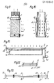
- a filter tube 2 having perforations 4 along a portion of its length and being closed at its lower end.
- This perforated portion is covered by a "skirt" of fibers 6 constituting the filter element.
- These fibers 6 are all of the same orientation, in this case axial, and, in their totality, constitute a substantial layer surrounding the tube 2.
- Such a layer is advantageously formed by several "sublayers” or “strata” of these fibers 6. It has been found that for the filter to be fully effective, at least three of such strata are required. At its upper end, this layer is firmly attached to the tube 2, for instance, by a length of wire or touch string 8 tightly wrapped around it. The lower ends of the fibers 6 are free.
- a longer tube 2 can be used with several filter elements mounted in succession, with the free ends of each "skirt” at least partly covering the wire-wound portion of the next lower “skirt".
- the filter element was, geometrically speaking, more or less tubular
- the embodiment shown in Fig. 2 has a flat filter element in the form of a substantially rectangular layer of fibers 6 stretchable between two rails 10, 12 and, in the filtering mode, substantially touching the perforated top surface 14 of the filter body 16 which, in this embodiment is not of a circular, but of a rectangular cross section and is not inside, but below, the filter layer.
- Fig. 3 shows an arrangement whereby such tightening.can be carried out.
- One end of the fibers 6 constituting the filter layer is fixedly attached to the rail 12, which is stationary.
- the other end is attached to a rail 18 which, guided by pins 20 slidably mounted in a bracket 22, can move in direction of the double arrow A.
- Also attached to the rail 18 is a bolt 24 having a nut 26 by means of which, against the elastic force of a compression spring 28, the rail 18 can be pulled towards the bracket 22, thus tightening the fibers 6.
- a precondition for proper filter action - the embodiment of Fig. 4 is provided with a top plate 30 which, urged by springs 31, presses the filter layer against the top surface 14 of the filter body 16.
- FIG. 5 An embodiment that combines the features of the embodiments of Figs. 3 and 4, i.e., tightens the fibers 6 as well as presses them close together, is seen in Fig. 5.
- the surface 14 of the filter body 16 is convex and the fibers 6 of the filter layer, fixedly attached on one end to a bracket 32, are tightened by the arrangement explained above in connection with Fig. 3. It is clearly seen that, due to the convexity of the top surface 14 of the filter body 16, tightening the fibers 6 will also cause them to be pressed one against the other.
- the filter elements according to the invention are defined as flushable, i.e., cleanable by application of a flushing liquid. Flushing can be facilitated by relieving whatever tension and/or pressure is exerted on the fibers. In the embodiments of Figs. 3-5 this is achieved by counteracting, using means as such known and not shown in the drawings, the forces producing tension and/or pressure. Thus, a lever arrangement could be used in the embodiment of Fig. 4 to temporarily lift the top plate 30 against the force of the springs 31 to remove the pressure from the fiber layer. In Figs. 3 and 5, an eccentric acting on the top of the bolt 24 should have a similar relieving effect that would permit the flushing fluid to reach all fibers.
- Fig. 6 has a conical filter body 16 provided with a cylindrical neck portion 34 and closed at its wider end.
- the perforated body 16 is covered by a "skirt" of filter fibers 6, the upper ends of which are attached to the body 16 by a length of wire or string 8, as was the case in the embodiment of Fig. 1.
- a bell-like member 35 Slidably mounted on the neck portion 34 of the filter body 16 there is provided a bell-like member 35 having a perforated, conical portion 36 and a cylindrical neck portion 38 slidingly fitting the neck portion of the filter body 16.
- the conicity of the conical portion 36 equals that of the outside surface of the "skirt" when mounted on the filter body 16.
- the bell-like member 35 can be moved in directions of the double arrow B. As shown in the drawing, the member 35 is in its lifted position, in which it makes no contact with the "skirt" of fibers 6. This would correspond to the flushing position, in which no pressure is exerted on the fibers.
- the member 35 is moved downwards, making contact with the fibers 6 and providing the required compaction pressure.
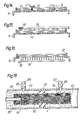
- FIG. 7 A different embodiment is shown in Figs. 7 and 8, in which the filter element is in the form of a substantially cylindrical coil obtained by winding the fiber 6 onto a cylindrical winding core, producing several layers. The winding core is then withdrawn and the fiber coil is transferred to a tubular filter core 40 having perforations 42. Except for an inward-bulging portion 44, the filter core 40 is cylindrical, but of an outside diameter slightly smaller than the outside diameter of the coil-winding core. Consequently the filter coil will.slip over the filter core 40 with clearance, as seen in Fig. 8. However, in order to produce a filtering effect, the fibers 6 have to be taut and close together. Fig.
- FIG. 7 representing the filtering mode, shows how this is achieved: a cam 46 is rotated, thereby progressively tightening the filter coil, until it is tightly pressed against the perforated portion of the filter core 40.
- this tension must be relaxed which is done by simply rotating the cam 461o its minimum displacement position, as shown in Fig. 8.
- the latter when preparing the filter coil, the latter must be somehow stabilized to prevent it from spontaneously unwinding as well as from losing its orderly structure. This is best done by applying some adhesive to the ends of the coil while still on the winding core, as well as along at least one generatrix of the cylindrical coil, or along a helix of a pitch equaling the length of the filter coil.
- a plurality of fibers 6 of equal length is attached on one end to an upper ring 48 and on the other end, to a lower ring 50, the two rings then being slipped onto a filter tube 2.
- the upper ring 48 is pinned to the tube 2 and is therefore stationary, the lower ring 50 can be rotated.
- the distance between the rings 48 and 50 is such that when the fibers 6 extend in the axial direction, they are slack, as shown in Fig. 10 which represents the flushing mode of the device.
- the lower ring 50 is given a twist, which turns the substantially vertical fibers 6 in Fig. 10 into helices tightly pressed against the tube 2 and its perforations 4.
- Means (not shown) are provided to arrest ring 50 in the twisted position. When released, a twist in the opposite sense will slacken the fibers 6 for the flushing mode.
- the filter element of which is a flat layer of fibers 6 stretchable between two rails 52 and 54 facilitates flushing by inducing the fibers 6 in differing strata of the filter element to perform a distinct reciprocating movement relative to fibers in other strata.
- the rails 52 and 54 are arranged to swivel about the axes 56 and 58, respectively.
- these axes lay in a plane passing through the center of the filter-element thickness. For instance, if the thickness of the element was made up of 5 layers or strata, this plane would pass through the third layer. In the vertical plane, the axes pass through the plane of attachment of the fibers 6 to the rails 52, 54. A swiveling movement of the rails 52, 54 about the axes 56, 58 respectively would thus turn the rectangular cross section of the filter element as seen in Figs. 11 and 12 into a rhomboid cross section, as indicated by broken lines in Fig. 12.
- Such a deformation would entail a relative sliding movement of the different strata or layers. It is such a relative movement that will loosen also sticky solids.
- the swivel movement required to produce the above effect is obtained, e.g., by an eccentric 60 acting on an arm 62 fixedly attached to the rail 52, against the restoring force of a compression spring 64.
- the eccentric 60 may be set rotating by a small turbine wheel driven by the mains water.
- a reciprocating movement of a larger amplitude is obtained by providing two fixed fiber rails 66 and 68, to whcih are fixedly attached all fibers of strata II and IV, while the fibers of strata I, III and V pass freely through rails 66 and 68, and are fixedly attached to rails 70 and 72.
- the relative fiber movement is obtained by keeping the rails 66 and 68 stationary, while imparting a reciprocating, in-phase movement to rails 70 and 72.
- Fig. 14 illustrates another cleaning method.
- the filter fibers 6 are threaded through a comb-like member 74, which, for purpose of cleaning, is imparted a reciprocating motion as indicated by the double arrow C, thereby mechanically scraping off the dirt deposited on the fibers 6.
- the dirt is then easily removed by flushing.
- a similar mechanical cleaning effect can be obtained by a number of stretched fibers 76 arranged in a vertical plane including with the filter fibers an angle of about 90 0 , each cleaning fiber passing between two adjacent strata of the filter fibers 6. When this fiber "comb" is passed from one end of the fiber layer to the other (double arrow D), dirt particles are scraped off.
- a preferred way of flushing the filter elements is by application of fluid jets against the filter layer.
- Seen in Fig. 15 is a flushing tube 78 arranged in proximity of the filter layer, from which tube, in the flushing mode of filter operation, issue a number of jets 80 that, upon impacting the layer, spread it apart locally, flushing out the dirt.
- the source of the flushing fluid is advantageously, though not necessarily, the fluid to be filtered.
- the jets 80 impacting the filter layer press the latter against the rigid surface 14 of the filter body 16, which with some types of solids may fail to achieve optimum results
- the arrangement shown in Fig. 16 in which the flushing tube 80 is located inside the filter body 16 has its jets 80 impacting the filter layer from below, that is, from the side of its support 82 which, in this case, has either large perforations or is in the form of a mesh-like structure that constitutes only a minimal resistance to the jets 80.
- the fluid to be filtered passes the fiber layer in a direction substantially perpendicular to the surface thereof, i.e., across the filter layer, it was found that an excellent filtering effect could also be obtained by haing the fluid pass inside the layer, along the fibers thereof, that is, inside the "capillary", as it were, formed between each group of three closely packed fibers.
- Fig. 17 shows a disposable filter element of this type, which can be used as an in-line filter.
- a rigid ring 84 around which are slung a plurality of filter fibers 6.
- the fibers 6, straddling the ring 84 are then introduced into a lower body member 88, the lower, cylindrical portion of which is completely filled with fibers all having the same, substantially axial, orientation.
- the upper portion of the lower body member 88 is flared and cupped, to accommodate the sealing ring 86.
- To this lower member 88 is then tightly attached an upper body member 90 by rolling over the edge 92 of the cupped end of the upper portion of member 88.
- the ends of the cylindrical portions of boty body members, 88 and 90 are flanged, to facilitate liquid-tight connection, via sealing rings 94, and by means of union nuts 96, to the respective ends of the pipeline sections 98.
- the arrows schematically indicate the fluid flow into, through, and out of the filter element.
- the union nuts 96 are opened and the entire device replaced.
- the union nuts 96 could obviously be also part of the pipeline sections 98, in which case the ends of the lower and upper body members, 88 and 90, would have to be provided with threaded sleeves attached to the respective cylindrical portions, e.g., by brazing.
- Fig. 18 As against the "throwaway" embodiment of Fig. 17, the filter shown in Fig. 18 is flushable.
- a length of pipe 100 connectable into a pipeline.
- a body member 102 preferably axially split, is attached to the inside of the pipe 100 and defines a central hollow space having a venturi- like shape, the wall surface of which space is lined with a sleeve-like filter layer composed of fibers 6 attached with their ends to rings 104.
- the active, central portion of the filter element is compacted by a hollow, perforated mandril 106 of a shape complementary to that of the fiber lining at this portion, and the fluid entering the filter layer above the mandril 106, as indicated by the arrows, is now compelled to pass through the above-mentioned "capillaries", leaving the layer again below the mandril 106.
- Flushing of the loaded filter element is initiated by stopping the mainline flow indicated by arrows A, lifting the mandril 106 for a short distance in direction of arrow B, and letting flushing fluid flow into the hollow mandril 106 in direction of arrow C.
- FIG. 19 Another flushable filter element is shown in Fig. 19 and has the form of an elongated rubber sleeve 110 provided with inlet-side perforations 112 and outlet-side perforations 113, and with a central collar 114 attachable to the inside wall of the pipeline 116.
- the sleeve 110 is provided with a first cover lid 118 through which passes a small pipe 120, and a second cover lid 122.
- the filter fibers 6, filling the entire cross section of the sleeve 110, are attached with their free ends to the two lids 118 and 122. Further provided are two flushing drains 124.
- the two drains 124 are closed by schematically indicated valves 126, and the fluid to be filtered flows from left to right as indicated by the arrows. Since the collar 114 prevents the fluid from bypassing the rubber sleeve 110, the fluid is forced to enter the sleeve via the inlet-side perforations 112 and the small pipe 120, whence it passes along the "capillaries" produced by the axially oriented fibers 6, leaving the sleeve 110 via the outlet-side perforations 113.
- Flushing is initiated by opening the two flushing-drain valves 126. This will produce a pressure drop in the annular space surrounding the sleeve 110 on both sides of the collar 114, with the pressure inside the sleeve 110 nearly full, due to the tube 120 which reaches inside the sleeve. The resulting pressure difference will slightly inflate the resilient rubber sleeve 110, relieving the compaction pressure keeping the fibers 6 tightly together. The fiber bundle is now loosened and the fluid sweeping through it easily cleans the individual fibers of any adhering deposit.
- Figs. 20 and 21 show a filter device according to the invention in the filtering and the flushing mode, respectively.
- the filter element used in this particular example is the tubular element shown in Fig. 1.
- the filter tube 2 and the "skirt" and its fibers 6 are seen to be accommodated in a housing 128 provided with a raw-water inlet 130 and a clean-fluid outlet 88.
- the filtering mode (Fig. 20)
- the raw fluid enters the housing 128 via a first multi-way valve 134 and, due to line pressure, is forced through the skirt of fibers 6 and the perforations 4 (Fig. 1) into the tube 2 and, via a second multi-way valve 32, into the clean-fluid outlet 132.
- Filtering obviously takes place when the fluid is forced through the fibers 6 which, in this embodiment, partly due to the water pressure acting upon them and partly due to their natural stiffness, form a rather tight layer penetrable by the fluid, but not by solid impurities. These solids are retained in the filter layer. After some time, dependent on the solids load and the filter throughput, the solid residue covering the fibers has to be removed. This is done by switching the multi-way valves 134 and 136 to the positions shown in Fig. 21. The filter now works in the flushing or, in this particular case, backflushing mode. Fluid from the inlet 130 now enters the tube 2 via multi-way valves 134 and 136 and, exiting the tube 2 via the perforations 4 (Fig.
- Backflushing can be initiated and concluded either manually or automatically.
- a transducer is provided which monitors the difference between the pressure in the filter housing 128 and that inside the tube 2, in other words, between filter inlet and outlet pressures.
- this difference exceeds a predetermined limit
- backflushing is initiated by switching the valves 134 and 136, as explained above. This switching action can be performed automatically, using appropriate actuators. After a predetermined flushing period, or after pressure difference has returned to normal, the valves 134,136 are again switched and filtering is resumed.
- Figs. 22 and 23 show another filter device according to the invention in the filtering and the flushing mode.
- This device uses the same element (Fig. 1) as the previous device, but the cleaning effect is produced by impact flushing rather than backflushing.
- raw-fluid enters the housing 128 via the inlet 130 and, forced by line pressure through the skirt of fibers 6 and the perforations 4 (Fig. I) into the tube 2, enters the clean-fluid outlet 132 via a multi-way valve 134.
- valve For flushing, the valve is brought to the position shown in Fig. 23, which causes the clean-fluid outlet 132 to be blocked and the flushing-fluid outlet 138 to be opened.
- the raw-fluid entering through the inlet 130 now impacts the fibers 6 from all sides, removes the solids and is discharged into the atmosphere or into a drain via the outlet 138.
- a substantially tubular filter-body arrangement is also obtainable with any of the above-mentioned flat filter configurations by providing a filter element having a filter body of a polygonal cross section, each face of such a body being covered by a flat filter layer such as those shown in Figs. 2 to 5 and 11 to 16.
- the fibers of the filter elements according to the invention can be made of any material compatible with the fluid to be filtered, optimum results were obtained for example with twisted synthetic fibers. It has been found that the surface texture imparted to the thread by the twisting operation provided just the right order of magnitude of intenstitial space permitting the fluid to pass without excessive pressure loss, while retaining all solids down to the smallest size which still needs tobe filtered out. It is of course also possible to use a single, nontwisted fiber having a texturized surface.
- the top surface of the filter body with a relatively rough texture. This will permit the fluid to get beneath the lowermost fibers of the fiber layer also at regions between any two perforations.
Landscapes
- Chemical & Material Sciences (AREA)
- Chemical Kinetics & Catalysis (AREA)
- Engineering & Computer Science (AREA)
- Water Supply & Treatment (AREA)
- Filtering Materials (AREA)
Priority Applications (6)
| Application Number | Priority Date | Filing Date | Title |
|---|---|---|---|
| AU12621/83A AU565461B2 (en) | 1983-03-21 | 1983-03-21 | A filter element for filtering fluids |
| DE8383301551T DE3377697D1 (en) | 1983-03-21 | 1983-03-21 | A filter element for filtering fluids |
| AT83301551T ATE36463T1 (de) | 1983-03-21 | 1983-03-21 | Filterelement zur filtration von stroemenden medien. |
| EP83301551A EP0119340B1 (de) | 1983-03-21 | 1983-03-21 | Filterelement zur Filtration von strömenden Medien |
| US06/788,699 US4617120A (en) | 1983-03-21 | 1985-10-21 | Filter element for filtering fluids |
| US06/917,206 US4915835A (en) | 1983-03-21 | 1986-10-09 | Flushable fiber-filter element for filtering a fluid |
Applications Claiming Priority (4)
| Application Number | Priority Date | Filing Date | Title |
|---|---|---|---|
| AU12621/83A AU565461B2 (en) | 1983-03-21 | 1983-03-21 | A filter element for filtering fluids |
| EP83301551A EP0119340B1 (de) | 1983-03-21 | 1983-03-21 | Filterelement zur Filtration von strömenden Medien |
| US47831083A | 1983-03-24 | 1983-03-24 | |
| US06/788,699 US4617120A (en) | 1983-03-21 | 1985-10-21 | Filter element for filtering fluids |
Publications (2)
| Publication Number | Publication Date |
|---|---|
| EP0119340A1 true EP0119340A1 (de) | 1984-09-26 |
| EP0119340B1 EP0119340B1 (de) | 1988-08-17 |
Family
ID=27422505
Family Applications (1)
| Application Number | Title | Priority Date | Filing Date |
|---|---|---|---|
| EP83301551A Expired EP0119340B1 (de) | 1983-03-21 | 1983-03-21 | Filterelement zur Filtration von strömenden Medien |
Country Status (3)
| Country | Link |
|---|---|
| US (1) | US4617120A (de) |
| EP (1) | EP0119340B1 (de) |
| AU (1) | AU565461B2 (de) |
Cited By (7)
| Publication number | Priority date | Publication date | Assignee | Title |
|---|---|---|---|---|
| EP0280052A1 (de) * | 1987-01-27 | 1988-08-31 | Dongbei Power College | Verfahren und Vorrichtung zum Filtrieren |
| WO1994011088A1 (en) * | 1992-11-09 | 1994-05-26 | John Reipur | Filtration medium |
| EP0623372A1 (de) * | 1993-04-28 | 1994-11-09 | Filtration Limited | Filterelement und Reinigungsvorrichtung |
| US6508942B2 (en) | 1999-12-20 | 2003-01-21 | Morimura Kousan Kabushiki Kaisha | Solid-liquid filtering method and system for sewage, waste water and the like |
| DE10012534C2 (de) * | 2000-03-13 | 2003-07-03 | Morimura Kousan K K | Fest-flüssig-Filterverfahren und -system für Abwasser und dgl. |
| US6776295B2 (en) | 1999-12-20 | 2004-08-17 | Morimura Kousan Kabushiki Kaisha | Solid-liquid filtering method and system for sewage, waste water and the like |
| WO2012046240A3 (en) * | 2010-10-07 | 2012-07-05 | Amiad Water Systems Ltd. | Fluid filtering unit and system |
Families Citing this family (9)
| Publication number | Priority date | Publication date | Assignee | Title |
|---|---|---|---|---|
| GB9623362D0 (en) * | 1996-11-09 | 1997-01-08 | Goodson Malcolm G | Method and apparatus for water treatment |
| CA2461460C (en) * | 2000-09-19 | 2010-06-22 | Fibra Limited | A device and a method for filtering a fluid |
| KR100453329B1 (ko) * | 2004-03-08 | 2004-10-21 | 주식회사 나노엔텍 | 밀도 조절형 섬유사 정밀여과장치 |
| US7501058B1 (en) * | 2007-05-11 | 2009-03-10 | Lawrence Sr Joseph W | Self-clearing strainer for fluid intake |
| US9416920B2 (en) * | 2012-04-19 | 2016-08-16 | Edgar Veinbergs | Adjustable liquid strainer |
| US20150108071A1 (en) | 2012-06-01 | 2015-04-23 | Desmi Ocean Guard A/S | De-ballast filtration |
| US9502144B2 (en) * | 2012-07-06 | 2016-11-22 | Westinghouse Electric Company Llc | Filter for a nuclear reactor containment ventilation system |
| US9993096B2 (en) | 2013-03-15 | 2018-06-12 | Bruce D. Frimerman | System and method for treating hiccups |
| US9440178B2 (en) * | 2014-06-23 | 2016-09-13 | Caterpillar Inc. | Pleated filter media |
Citations (5)
| Publication number | Priority date | Publication date | Assignee | Title |
|---|---|---|---|---|
| DE98685C (de) * | ||||
| DE1959867A1 (de) * | 1968-11-28 | 1970-06-11 | Arai Sinzo | Filter |
| GB1200208A (en) * | 1966-11-14 | 1970-07-29 | Koehler Dayton | A filter |
| DE2249603A1 (de) * | 1971-10-15 | 1973-04-19 | Ishigaki Mech Ind | Filterelement |
| FR2461513A1 (fr) * | 1979-05-28 | 1981-02-06 | Zhdanovskij Metall Inst | Filtre pour l'epuration de fluides charges de particules |
Family Cites Families (10)
| Publication number | Priority date | Publication date | Assignee | Title |
|---|---|---|---|---|
| US1991847A (en) * | 1932-12-20 | 1935-02-19 | Durgen Leo | Filter |
| US2807501A (en) * | 1954-07-19 | 1957-09-24 | Dorr Oliver Inc | Shower actuating mechanism |
| DE1798208C3 (de) * | 1968-09-07 | 1973-10-04 | Jenaer Glaswerk Schott & Gen, 6500 Mainz | Trennsäule für die Flussigkeits Chromatographie und Verfahren zu ihrer Herstellung |
| CH532409A (fr) * | 1970-09-04 | 1973-01-15 | Doucet Charles | Procédé de filtrage d'un fluide et filtre pour la mise en oeuvre de ce procédé |
| SE369747B (de) * | 1972-03-29 | 1974-09-16 | Celleco Ab | |
| SE7710010L (sv) * | 1976-10-11 | 1978-04-12 | Mueller Hans | Forfarande och anordning for filtrering av vetskor och gaser samt anvendning av forfarandet resp anordningen |
| BR7703877A (pt) * | 1977-06-14 | 1977-11-01 | L Silva | Tratamento de agua com a manta bidim |
| CH633196A5 (de) * | 1978-03-02 | 1982-11-30 | Chemap Ag | Verfahren und buerstenfilter zur filtration von fluessigkeiten und gasen. |
| US4299699A (en) * | 1980-10-14 | 1981-11-10 | Boogay Marc A | Backwashable helical-media coalescer |
| DE3047967C2 (de) * | 1980-12-19 | 1985-12-12 | Felix Schoeller jr. GmbH & Co KG, 4500 Osnabrück | Füllmaterial für einen Tropfkörper für die biologische Abwasserreinigung |
-
1983
- 1983-03-21 EP EP83301551A patent/EP0119340B1/de not_active Expired
- 1983-03-21 AU AU12621/83A patent/AU565461B2/en not_active Ceased
-
1985
- 1985-10-21 US US06/788,699 patent/US4617120A/en not_active Expired - Lifetime
Patent Citations (5)
| Publication number | Priority date | Publication date | Assignee | Title |
|---|---|---|---|---|
| DE98685C (de) * | ||||
| GB1200208A (en) * | 1966-11-14 | 1970-07-29 | Koehler Dayton | A filter |
| DE1959867A1 (de) * | 1968-11-28 | 1970-06-11 | Arai Sinzo | Filter |
| DE2249603A1 (de) * | 1971-10-15 | 1973-04-19 | Ishigaki Mech Ind | Filterelement |
| FR2461513A1 (fr) * | 1979-05-28 | 1981-02-06 | Zhdanovskij Metall Inst | Filtre pour l'epuration de fluides charges de particules |
Cited By (13)
| Publication number | Priority date | Publication date | Assignee | Title |
|---|---|---|---|---|
| EP0280052A1 (de) * | 1987-01-27 | 1988-08-31 | Dongbei Power College | Verfahren und Vorrichtung zum Filtrieren |
| WO1994011088A1 (en) * | 1992-11-09 | 1994-05-26 | John Reipur | Filtration medium |
| US5690823A (en) * | 1992-11-09 | 1997-11-25 | Reipur; John | Filtration medium |
| EP0623372A1 (de) * | 1993-04-28 | 1994-11-09 | Filtration Limited | Filterelement und Reinigungsvorrichtung |
| US5514270A (en) * | 1993-04-28 | 1996-05-07 | Filtration Ltd. | Plural layer fiber filter element and system for cleaning |
| US6776295B2 (en) | 1999-12-20 | 2004-08-17 | Morimura Kousan Kabushiki Kaisha | Solid-liquid filtering method and system for sewage, waste water and the like |
| US6508942B2 (en) | 1999-12-20 | 2003-01-21 | Morimura Kousan Kabushiki Kaisha | Solid-liquid filtering method and system for sewage, waste water and the like |
| DE10012534C2 (de) * | 2000-03-13 | 2003-07-03 | Morimura Kousan K K | Fest-flüssig-Filterverfahren und -system für Abwasser und dgl. |
| WO2012046240A3 (en) * | 2010-10-07 | 2012-07-05 | Amiad Water Systems Ltd. | Fluid filtering unit and system |
| AU2011311175A1 (en) * | 2010-10-07 | 2013-05-02 | Amiad Water Systems Ltd. | Fluid filtering unit and system |
| US9347570B2 (en) | 2010-10-07 | 2016-05-24 | Amiad Water Systems Ltd | Fluid filtering unit and system |
| AU2011311175B2 (en) * | 2010-10-07 | 2016-06-30 | Amiad Water Systems Ltd. | Fluid filtering unit and system |
| AU2016231580B2 (en) * | 2010-10-07 | 2018-03-15 | Amiad Water Systems Ltd. | Fluid filtering unit and system |
Also Published As
| Publication number | Publication date |
|---|---|
| AU1262183A (en) | 1984-09-27 |
| US4617120A (en) | 1986-10-14 |
| EP0119340B1 (de) | 1988-08-17 |
| AU565461B2 (en) | 1987-09-17 |
Similar Documents
| Publication | Publication Date | Title |
|---|---|---|
| US4617120A (en) | Filter element for filtering fluids | |
| US4299699A (en) | Backwashable helical-media coalescer | |
| US4915835A (en) | Flushable fiber-filter element for filtering a fluid | |
| US2301430A (en) | Filter | |
| EP0280052B1 (de) | Verfahren und Vorrichtung zum Filtrieren | |
| US5207930A (en) | Filtration system with helical filter cartridge | |
| DE3888522T2 (de) | Vorrichtung und verfahren zum filtrieren. | |
| US2643772A (en) | Filter | |
| CN1463201A (zh) | 孔隙尺寸可调的过滤器 | |
| DE3915354A1 (de) | Vibrationssiebeinheit mit filter sowie verfahren zur reinigung des filters | |
| US3310175A (en) | Filter | |
| US3975274A (en) | Process and device for filtering media | |
| EP0077086A2 (de) | Verfahren zur Reinigung von Filterelementen | |
| DE2922549A1 (de) | Filter | |
| US3527351A (en) | Fluid filtering apparatus | |
| DE2249603A1 (de) | Filterelement | |
| DE3785200T2 (de) | Filtrationsapparat. | |
| US2699260A (en) | Filter media | |
| US4944887A (en) | Regenerative diatomaceous earth filter | |
| KR20190050014A (ko) | 당김과 비틀림을 동시 적용한 섬유여과장치 | |
| US6051138A (en) | Slack filter tube with tensioning means | |
| CA1222958A (en) | Filter element for filtering fluids | |
| EP0634199B1 (de) | Wasserfeinfilter mit einstellbarer Filter- und Rückspülfunktion | |
| DE19942240C2 (de) | Feinfilter für eine Regenwassersammelanlage | |
| JPS63294911A (ja) | 濾過機 |
Legal Events
| Date | Code | Title | Description |
|---|---|---|---|
| PUAI | Public reference made under article 153(3) epc to a published international application that has entered the european phase |
Free format text: ORIGINAL CODE: 0009012 |
|
| AK | Designated contracting states |
Designated state(s): AT BE CH DE FR GB IT LI NL SE |
|
| 17P | Request for examination filed |
Effective date: 19850322 |
|
| 17Q | First examination report despatched |
Effective date: 19860127 |
|
| D17Q | First examination report despatched (deleted) | ||
| GRAA | (expected) grant |
Free format text: ORIGINAL CODE: 0009210 |
|
| RAP1 | Party data changed (applicant data changed or rights of an application transferred) |
Owner name: FILTRATION WATER FILTERS FOR AGRICULTURE AND INDUS |
|
| AK | Designated contracting states |
Kind code of ref document: B1 Designated state(s): AT BE CH DE FR GB IT LI NL SE |
|
| REF | Corresponds to: |
Ref document number: 36463 Country of ref document: AT Date of ref document: 19880915 Kind code of ref document: T |
|
| REF | Corresponds to: |
Ref document number: 3377697 Country of ref document: DE Date of ref document: 19880922 |
|
| ET | Fr: translation filed | ||
| ITF | It: translation for a ep patent filed | ||
| PLBE | No opposition filed within time limit |
Free format text: ORIGINAL CODE: 0009261 |
|
| STAA | Information on the status of an ep patent application or granted ep patent |
Free format text: STATUS: NO OPPOSITION FILED WITHIN TIME LIMIT |
|
| 26N | No opposition filed | ||
| REG | Reference to a national code |
Ref country code: GB Ref legal event code: 732B |
|
| REG | Reference to a national code |
Ref country code: CH Ref legal event code: PFA Free format text: FILTRATION LIMITED |
|
| NLT1 | Nl: modifications of names registered in virtue of documents presented to the patent office pursuant to art. 16 a, paragraph 1 |
Owner name: FILTRATION LTD. TE HERZLIA, ISRAEL. |
|
| REG | Reference to a national code |
Ref country code: CH Ref legal event code: PUE Owner name: FILTRATION LIMITED |
|
| REG | Reference to a national code |
Ref country code: GB Ref legal event code: 732 |
|
| ITPR | It: changes in ownership of a european patent |
Owner name: CESSIONE;YTZHAK BARZUZA |
|
| REG | Reference to a national code |
Ref country code: FR Ref legal event code: TP |
|
| ITTA | It: last paid annual fee | ||
| NLS | Nl: assignments of ep-patents |
Owner name: FILTRATION LTD. TE HERZLIA EN YTZHAK BARZUZA TE PE |
|
| EAL | Se: european patent in force in sweden |
Ref document number: 83301551.4 |
|
| PGFP | Annual fee paid to national office [announced via postgrant information from national office to epo] |
Ref country code: SE Payment date: 19990305 Year of fee payment: 17 |
|
| PGFP | Annual fee paid to national office [announced via postgrant information from national office to epo] |
Ref country code: FR Payment date: 19990309 Year of fee payment: 17 |
|
| PGFP | Annual fee paid to national office [announced via postgrant information from national office to epo] |
Ref country code: AT Payment date: 19990311 Year of fee payment: 17 |
|
| PGFP | Annual fee paid to national office [announced via postgrant information from national office to epo] |
Ref country code: GB Payment date: 19990325 Year of fee payment: 17 |
|
| PGFP | Annual fee paid to national office [announced via postgrant information from national office to epo] |
Ref country code: DE Payment date: 19990326 Year of fee payment: 17 |
|
| PGFP | Annual fee paid to national office [announced via postgrant information from national office to epo] |
Ref country code: NL Payment date: 19990329 Year of fee payment: 17 Ref country code: CH Payment date: 19990329 Year of fee payment: 17 |
|
| PGFP | Annual fee paid to national office [announced via postgrant information from national office to epo] |
Ref country code: BE Payment date: 19990517 Year of fee payment: 17 |
|
| PG25 | Lapsed in a contracting state [announced via postgrant information from national office to epo] |
Ref country code: GB Free format text: LAPSE BECAUSE OF NON-PAYMENT OF DUE FEES Effective date: 20000321 Ref country code: AT Free format text: LAPSE BECAUSE OF NON-PAYMENT OF DUE FEES Effective date: 20000321 |
|
| PG25 | Lapsed in a contracting state [announced via postgrant information from national office to epo] |
Ref country code: SE Free format text: LAPSE BECAUSE OF NON-PAYMENT OF DUE FEES Effective date: 20000322 |
|
| PG25 | Lapsed in a contracting state [announced via postgrant information from national office to epo] |
Ref country code: LI Free format text: LAPSE BECAUSE OF NON-PAYMENT OF DUE FEES Effective date: 20000331 Ref country code: CH Free format text: LAPSE BECAUSE OF NON-PAYMENT OF DUE FEES Effective date: 20000331 Ref country code: BE Free format text: LAPSE BECAUSE OF NON-PAYMENT OF DUE FEES Effective date: 20000331 |
|
| BERE | Be: lapsed |
Owner name: BARZUZA YTZHAK Effective date: 20000331 Owner name: FILTRATION WATER FILTERS FOR AGRICULTURE AND INDU Effective date: 20000331 |
|
| PG25 | Lapsed in a contracting state [announced via postgrant information from national office to epo] |
Ref country code: NL Free format text: LAPSE BECAUSE OF NON-PAYMENT OF DUE FEES Effective date: 20001001 |
|
| EUG | Se: european patent has lapsed |
Ref document number: 83301551.4 |
|
| GBPC | Gb: european patent ceased through non-payment of renewal fee |
Effective date: 20000321 |
|
| REG | Reference to a national code |
Ref country code: CH Ref legal event code: PL |
|
| PG25 | Lapsed in a contracting state [announced via postgrant information from national office to epo] |
Ref country code: FR Free format text: LAPSE BECAUSE OF NON-PAYMENT OF DUE FEES Effective date: 20001130 |
|
| NLV4 | Nl: lapsed or anulled due to non-payment of the annual fee |
Effective date: 20001001 |
|
| REG | Reference to a national code |
Ref country code: FR Ref legal event code: ST |
|
| PG25 | Lapsed in a contracting state [announced via postgrant information from national office to epo] |
Ref country code: DE Free format text: LAPSE BECAUSE OF NON-PAYMENT OF DUE FEES Effective date: 20010103 |