EP0119364A1 - Verfahren und Vorrichtung zum Handhaben von Teilen, insbesondere von kleinen Teilen in der Massenfertigung - Google Patents
Verfahren und Vorrichtung zum Handhaben von Teilen, insbesondere von kleinen Teilen in der Massenfertigung Download PDFInfo
- Publication number
- EP0119364A1 EP0119364A1 EP83402518A EP83402518A EP0119364A1 EP 0119364 A1 EP0119364 A1 EP 0119364A1 EP 83402518 A EP83402518 A EP 83402518A EP 83402518 A EP83402518 A EP 83402518A EP 0119364 A1 EP0119364 A1 EP 0119364A1
- Authority
- EP
- European Patent Office
- Prior art keywords
- axis
- face
- vehicle
- jacket
- channel
- Prior art date
- Legal status (The legal status is an assumption and is not a legal conclusion. Google has not performed a legal analysis and makes no representation as to the accuracy of the status listed.)
- Withdrawn
Links
- 238000000034 method Methods 0.000 title claims description 31
- 230000008569 process Effects 0.000 title description 9
- 230000002093 peripheral effect Effects 0.000 claims description 74
- 238000012546 transfer Methods 0.000 claims description 67
- 238000013519 translation Methods 0.000 claims description 23
- 230000000295 complement effect Effects 0.000 claims description 13
- 230000000717 retained effect Effects 0.000 claims description 10
- 230000000694 effects Effects 0.000 claims 1
- 238000009434 installation Methods 0.000 abstract 1
- 230000037452 priming Effects 0.000 description 36
- 230000014616 translation Effects 0.000 description 16
- 238000011161 development Methods 0.000 description 5
- 230000008901 benefit Effects 0.000 description 4
- 208000031968 Cadaver Diseases 0.000 description 3
- 230000000977 initiatory effect Effects 0.000 description 3
- 238000004519 manufacturing process Methods 0.000 description 3
- 238000012986 modification Methods 0.000 description 3
- 230000004048 modification Effects 0.000 description 3
- 230000035515 penetration Effects 0.000 description 3
- 238000003825 pressing Methods 0.000 description 3
- 241000699729 Muridae Species 0.000 description 2
- 230000006978 adaptation Effects 0.000 description 2
- 238000013461 design Methods 0.000 description 2
- 238000006073 displacement reaction Methods 0.000 description 2
- 238000005304 joining Methods 0.000 description 2
- 238000003754 machining Methods 0.000 description 2
- 239000000463 material Substances 0.000 description 2
- 235000013580 sausages Nutrition 0.000 description 2
- 238000000926 separation method Methods 0.000 description 2
- 229910001141 Ductile iron Inorganic materials 0.000 description 1
- 229910000760 Hardened steel Inorganic materials 0.000 description 1
- 230000001174 ascending effect Effects 0.000 description 1
- 238000012550 audit Methods 0.000 description 1
- 230000008859 change Effects 0.000 description 1
- 238000004891 communication Methods 0.000 description 1
- 230000006835 compression Effects 0.000 description 1
- 238000007906 compression Methods 0.000 description 1
- 230000001143 conditioned effect Effects 0.000 description 1
- 239000000470 constituent Substances 0.000 description 1
- 238000010924 continuous production Methods 0.000 description 1
- 238000007599 discharging Methods 0.000 description 1
- 238000004880 explosion Methods 0.000 description 1
- 238000003780 insertion Methods 0.000 description 1
- 230000037431 insertion Effects 0.000 description 1
- 230000000670 limiting effect Effects 0.000 description 1
- 238000012423 maintenance Methods 0.000 description 1
- 230000036961 partial effect Effects 0.000 description 1
- 230000000149 penetrating effect Effects 0.000 description 1
- 230000010287 polarization Effects 0.000 description 1
- 239000000843 powder Substances 0.000 description 1
- 238000004321 preservation Methods 0.000 description 1
- 230000000750 progressive effect Effects 0.000 description 1
- 238000011084 recovery Methods 0.000 description 1
- 230000002829 reductive effect Effects 0.000 description 1
- 230000000284 resting effect Effects 0.000 description 1
- 230000007704 transition Effects 0.000 description 1
Images


Classifications
-
- F—MECHANICAL ENGINEERING; LIGHTING; HEATING; WEAPONS; BLASTING
- F42—AMMUNITION; BLASTING
- F42B—EXPLOSIVE CHARGES, e.g. FOR BLASTING, FIREWORKS, AMMUNITION
- F42B33/00—Manufacture of ammunition; Dismantling of ammunition; Apparatus therefor
- F42B33/04—Fitting or extracting primers in or from fuzes or charges
-
- B—PERFORMING OPERATIONS; TRANSPORTING
- B23—MACHINE TOOLS; METAL-WORKING NOT OTHERWISE PROVIDED FOR
- B23P—METAL-WORKING NOT OTHERWISE PROVIDED FOR; COMBINED OPERATIONS; UNIVERSAL MACHINE TOOLS
- B23P19/00—Machines for simply fitting together or separating metal parts or objects, or metal and non-metal parts, whether or not involving some deformation; Tools or devices therefor so far as not provided for in other classes
- B23P19/008—Machines for simply fitting together or separating metal parts or objects, or metal and non-metal parts, whether or not involving some deformation; Tools or devices therefor so far as not provided for in other classes the parts being continuously transported through the machine during assembling or disassembling
Definitions
- the present invention relates to the handling of parts and more particularly to the continuous handling of small parts to which it is desired to maintain a predetermined orientation during handling, with a view to their presentation at a machining or assembly station.
- An example of such parts is constituted by ammunition primers which it is important to present at an insertion station in respective bases of ammunition casings according to a precise orientation, essential for introduction without risk of accidents.
- a device constituted by a rigid block, for example metallic comprising a channel of generally rectilinear axis and of generally constant section transversely to this axis, to receive and retain the part in this channel, in a determined orientation relative to the axis thereof, during handling operations, and then restore the part having retained this orientation.
- vehicle constituted by a rigid block, for example metallic comprising a channel of generally rectilinear axis and of generally constant section transversely to this axis, to receive and retain the part in this channel, in a determined orientation relative to the axis thereof, during handling operations, and then restore the part having retained this orientation.
- the slightest inaccuracy in the alignment of the channel of the vehicle and of the housing of the socket can lead, to the passage of the channel to this housing, in an area where the guidance of the primer therefore experiences a discontinuity, warping and jamming of the primer, with the risk of explosion.
- a method which consists of scrolling the cartridge cases one by one under a transfer press under which the primers, placed for example in a hopper, are brought one by one by a slide system; when a sleeve is under the press, the running of the sleeves is interrupted and the press introduces a primer, brought in the meantime by the slide system, into the base of the sleeve thus stopped; the row of sockets then advances by one step, that is to say the distance between two sockets, and the operation resumes.
- This technique makes it possible to ensure a precise relative positioning of the primers and their housing on introduction, but has the disadvantage of a relative slowness, due to mechanical imperatives; integrated into a production line working elsewhere in continuous kinematics, it prevents using this technique of continuous kinematics to the full extent of its possibilities.
- the object of the present invention is to make it possible to apply the technique of continuous kinematics to such parts, by providing a vehicle which not only is capable of receiving and maintaining such a part in a predetermined orientation during handling up to at a station where this part must be returned by the vehicle, but also be suitable for allowing such return, in particular by introduction into an appropriate housing of an object, under the same conditions of safety as regards preservation of the predetermined orientation.
- the present invention proposes to give the vehicle a structure such that, as soon as it occupies a predetermined position with respect to a tool fitted to the station where the restitution is to take place, it forms an integral part of this tool, so as to cooperate with the latter in the return of a part which he brought to this station.
- the vehicle according to the present invention of the type comprising a channel having a rectilinear axis and a constant section transverse to this axis for internally receiving a part for its handling and then restoring it, is characterized in that it comprises at least one jacket delimiting the channel and a body external to this channel and with respect to which the jacket is mounted with the possibility of relative translation parallel to the axis, so as to cooperate with means for transferring the part outside the channel by being dissociable from these means.
- such a vehicle can advantageously be used in addition to the device described by French patent n ° 82 00801, which allows parts to be introduced into vehicles at the right rate. '' one part per channel of a vehicle, the body and the jacket of this vehicle being vertical and retained against a relative sliding by pressing down and up against counterparts of the machine (references 75 and 83 of this document).
- the vehicle containing the part During the handling of the vehicle containing the part, it can be maintained inside the channel either by friction, due to an appropriate choice of the dimensions of the channel according to those of the part, or more advantageously by stops also ensuring the maintenance of the liner inside the body, the part then being mounted to slide freely, but with close adjustment, inside the vehicle channel.
- the jacket and the body are delimited, transversely with respect to the axis, by two respective end faces perpendicular to this axis, and the respective lengths of the body and of the jacket, measured between their respective end faces, parallel to the axis, are equal so that, during a relative translation parallel to the axis, the jacket and the body can be brought into a privileged state in which their respective end faces are coplanar two by two , which defines the state of the vehicle when a part is inserted into the channel and during handling.
- the jacket is tubular and has an inner peripheral face delimiting the channel and an outer peripheral face of constant section transverse to the axis
- the body has an inner peripheral face of constant section transversely to the axis and complementary to that of this outer periphery face to ensure by mutual sliding contact the possibility of relative translation of the body and of the sleeve, from a privileged state in which the sleeve is engaged as much as possible in the body, and their respective end faces are coplanar two by two if one also adopts the preferred arrangement mentioned above.
- the vehicle then constitutes an active element in the implementation of the method, the transfer being accompanied by relative guidance of the part and of the object due to the relative translation of the jacket and of the body.
- the inner peripheral face of the body and / or the outer peripheral face of the jacket have at least one chamfered end transversely to the axis, which makes it possible to cause said relative translation of the jacket and of the body up to that they are completely disengaged from each other without encountering difficulty in then bringing them back to said privileged state;
- the inner peripheral face of the body and / or the outer peripheral face of the jacket may advantageously have a helical stripe.
- the part has a cylindrical outer periphery of revolution about an axis which merges with the axis of the channel when the part is engaged inside of it, and the angular position of the part around its axis the introduction into the housing of the object is indifferent, as is the case with the ammunition primers, the respective inner and outer peripheral faces of the jacket and of the body are cylindrical of revolution around the axis, which makes it possible to handle the vehicle and to place it in the axis of the object housing with a view to introducing it in a particularly simple manner.
- a device comprising, on a work station, means for receiving in said relative position an object and a vehicle according to the invention in said privileged state and in the channel from which a part is retained, and means for effecting the transfer of the part from the channel to the housing by translation of the part in the channel along the axis thereof ,
- the means for effecting the transfer comprise means for applying opposing thrusts along the axis of the channel on the one hand to the object and to the jacket and on the other hand to the body and to the part, in the direction of an introduction of the object into the body and of the part in the housing of the object from said privileged state, and then to bring the vehicle to said privileged state.
- the jacket and the body of the vehicle then form an integral part of the tooling of the work station, with which they cooperate in the introduction of the part into the housing of the object.
- this device practices the aforementioned operations a and b by retaining the body of the vehicle and the part against a movement, in particular along the axis of the channel, and by driving the jacket relative to the body and to the next part.
- this axis by a thrust applied via the object which is introduced into the body thus retained, by a relative translation along this axis, until the housing receives the part.
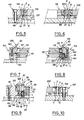
- the illustrated vehicle is formed of a body 1 and a jacket 2 both tubular, independent and separable.
- the body 1 is delimited by two cylindrical faces of revolution about the same axis 3, on the basis of an inner peripheral face 4 and an outer peripheral face 5, connected by two annular end faces 6,7, planar , oriented perpendicular to the axis 3 and chamfered respectively at 33 , 34 at their junction with the face 5; similarly, the jacket 2 is delimited by two cylindrical faces of revolution about the same axis 8, on the basis of an inner peripheral face 9 and an outer peripheral face 10, connected by two annular end faces 11, 12, flat, and oriented perpendicular to the axis 8.
- the outer peripheral face 10 of the jacket 2 and the inner peripheral face 4 of the body 1 are carefully polished and have respective diameters D 1 and D 2 substantially equal, so that the liner 2 can be engaged in the body 1 in a position in which their respective axes 8 and 3 coincide, and that the faces 10 and 4 then placed in contact provide guidance for relative sliding, by mutual sliding contact, parallel to axes 8 and 3 then combined.
- the inner peripheral face 4 of the body 1 is connected to the faces 6 and 7 of the latter by chamfers, respectively 13 and 14, and the outer peripheral face 10 of the jacket 2 is connected to the faces 11 and 12 of the latter by two other chamfers, respectively 15 and 16, all of these chamfers or some of them being able to be omitted in other embodiments of the vehicle.
- the inner peripheral face 4 of the body 1 is provided with a helical stripe 28 of axis 3; the outer peripheral face 10 of the jacket 2 could also be provided with a helical stripe of axis 8, the stripe 28 then being preferably omitted.
- the faces 11 and 12 of the jacket 2 are distant, parallel to the axis 8, of a length L 1 equal to the length L 2 of the body 1, measured parallel to the axis 3 between its faces 6 and 7 so that, by relative translation parallel to their axes 8 and 3 combined, the jacket 2 and the body 1 can be brought in particular into a privileged state in which the jacket 2 is engaged to the maximum in the body 1, and the faces 11 and 12 are coplanar with the faces 6 and 7 respectively.
- the jacket 2 defines a channel 17 of axis 8, suitable for receiving a primer, for example of the type illustrated in FIG. 16 or of the type illustrated in FIG. 18.
- these primers are delimited externally by an external peripheral face, respectively 20 or 21, cylindrical of revolution around an axis, respectively 22 or 23, of a cup, respectively 24 or 25, by a bottom face, respectively 26 or 27, of this bucket, flat and oriented perpendicular to the respective axis 22 or 23, and by another face of medium transverse orientation relative to the respective axis, respectively 29 or 30, corresponding to an open face of the cup, partially closed by an insert; naturally, the vehicle could be used for handling primers of other types, for example having a curved bottom face.
- the channel 17 has a diameter D 3 , defined by the diameter of the inner peripheral face 9 of the jacket 2, as close as possible to the diameter D 4 or From the outer peripheral face 20 or 21 of the primer 18 or 19; the diameter D 3 can be chosen, depending on the diameter D 4 or D 5 , so as to immobilize the primer 18 or 19 inside the jacket 2 by friction of the face 20 or 21 against face 9 but, preferably, face 9 is carefully polished, and has a diameter D 3 greater by a few hundredths of a millimeter than diameter D 4 or D S so that the primer 18 or 19 is free to slide parallel to the axis 8, with which its axis 22 or 23 coincides, with respect to the jacket 2, inside the channel 17 thereof.
- the inner peripheral face 9 of the jacket 2 is advantageously connected to one at least of the end faces 11 and 12 thereof by a chamfer , here provided at the two ends where it is designated respectively by the reference 31 and by the reference 32.
- the vehicle which has just been described is more particularly suitable, by the cylindrical shape of revolution of the respective internal and external peripheral faces of the body 1 and of the jacket 2, for handling parts which, like the primers 18 or 19, do not must not necessarily have an angular orientation determined with reference to their axis 22 or 23, that is to say with respect to the axis 8 defining the axis of the channel 17; it would not go beyond the scope of the invention to provide that the respective inner and outer peripheral faces of the body 1 and of the jacket 2 have cross sections with respect to their respective axes 3 or 8 which are not of revolution around this axis, in order to associate each part with a determined angular orientation, with reference to axes 8 and 3 combined, not only vis-à-vis the inner peripheral face 9 of the jacket 2 delimiting the channel 17, but also vis-à-vis the outer peripheral face 5 of the body 1,.
- the choice of the constituent materials respectively of the body 1 and of the shirt 2 is within the domain of the normal skills of a person skilled in the art; by way of nonlimiting example, good results have been obtained by choosing for the body a hardened steel (100C6 for bearing) to give it good mechanical resistance and correct friction, and for the liner a spheroidal graphite cast iron (GS 600) compatible with the body material for friction.
- a hardened steel 100C6 for bearing
- GS 600 spheroidal graphite cast iron
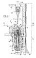
- a method of introducing a primer 18 or 19 into a housing 35 or 36 of the base 37 or 38 of a socket 39 or 40 ( Figures 17 and 19) by means of a vehicle 68 resulting from the combination of a body 1 and a jacket 2 of the tubular type, of revolution, illustrated, whose respective lengths L2 and L1 are equal, will now be described in its implementation by means of a device more particularly illustrated in Figures 3 at 15.
- FIGS. 17 and 19 show two nonlimiting examples of sockets capable of being thus primed
- the housing 35 or 36 arranged in the base 37 or 38 of a socket 39 or 40 having an axis 41 or 42 opens into a flat annular face 43 or 44 of this base, oriented perpendicular to the axis 41 or 42 on which it is centered; it is delimited inside the base 37 or 38 by an inner peripheral face 45 or 46, cylindrical of revolution around the axis 41 or 42 with a diameter lower by a few hundredths of a millimeter to the diameter D 4 or D5 of the outer peripheral face 20 or 21 of the primer 18 or 19, to receive the latter and immobilize it by friction in a position where its axis 22 or 23 coincides with the axis 41 or 42 of the sleeve, and by a flat bottom face 47 or 48, oriented transversely with respect to the axis 41 or 42, along which opens into this face, in accordance with the nonlimiting examples illustrated, a vent 49 or 50
- the device is supplied and served in continuous kinematics, as in the illustrated example where it is integrated into a continuous production line.
- FIGS. 3 and 4 which illustrate part of this chain, one sees at 53 a priming barrel having a vertical axis 54 around which it is rotated in a determined direction 55 by any means suitable for the field of knowledge in the fall of the trade, this barrel 53 having an outer periphery 56 along which are arranged initiation stations 57 each of which has its own axis 58, parallel to the axis 54, the various axes 58 being uniformly distributed angularly if reference is made to the axis 54 and placed at the same distance therefrom, so as to describe, during the rotation of the barrel 53 in the direction 55 around the axis 54, a primitive cylinder 59 of revolution around the axis 54.
- FIGS. 11 to 13 The detail of a priming station 57 is more particularly visible in FIGS. 11 to 13, where the same references have been used to designate the same elements, although these are placed in different relative arrangements corresponding to different stages of priming.
- the barrel 53 is in the form of a sleeve having, in addition to its outer periphery 56 of general shape of revolution around the axis 54, an inner periphery 60 also of revolution around this axis, and by which it is mounted on the outer periphery 61, also of revolution about the axis 54, of a central shaft 62 fixed relative to the ground; mounting the inner periphery 60 of the barrel 53 on the outer periphery 61 of the shaft 62 is ensured by any means within the field of knowledge of those skilled in the art, ensuring a possibility of relative rotation about the axis 54, as well that a support of the barrel 53 against a translation in particular downwards, parallel to the axis 54, relative to the shaft 62.
- the outer periphery 56 of the barrel 53 carries a solidly support block 63 projecting in the direction of a distance from the axis 54, which block 63 carries itself even integrally, at its upper part, a plate 64 have a planar upper face 65, perpendicular to the axis 54, that is to say horizontal.
- This plate 64 is pierced right through with a hole 66 delimited by a cylindrical face 67 of revolution about an axis parallel to the axis 54 and defining the axis 58 of the priming station 57, with a smaller diameter to the diameter D 6 of the.
- the support block 63 also carries, in an integral manner, above the face 65 of this plate 64, a positioning block 69 integrally located between the primitive cylinder 59 and the axis 54 and having immediately above the face 65 a cell 70 open in the direction of a distance from the axis 54; this cell 70 has, between the face 65 and a horizontal level located above the latter, at a distance from the latter equal to the height of the body 1 , measured along the axis 58, that is to say say at length L2, at least one bearing surface for the outer peripheral face 5 of the body 1; in the example illustrated, two bearing surfaces 7 1 and 72 are thus provided with respect to which the rest of the cell 70 is set back towards the axis 54; these bearing surfaces 71 and 72 are placed respectively in the immediate vicinity of the upper face 65 of the plate 64, which defines for the cavity 70 a lower face, and in the immediate proximity of the aforementioned level, to serve as support for the outer peripheral face 5 of the body 1 respectively
- the support block 63 carries, essentially below the plate 64, a lower punch 74 and a slide 75 both of revolution around the axis 58, and entering a coaxial arrangement with inside the hole 66 of the plate 64.
- the lower punch 74 is intended to remain fixed with respect to the support block 3, that is to say with respect to the barrel 53, in a position in which it has an upper face 76 in the form of a flat disc transverse to the axis 58, with a diameter at more equal to the diameter D 3 of the inner peripheral face 9 of the jacket 2, in coplanarity with the face 65 so as to retain the primer 19, by the bottom face 27 thereof in contact with this face 76, in such coplanarity during the entire duration of the priming process.
- the punch 74 is retractable elastically downwards relative to this privileged position; for this purpose, it is housed at its lower part in a slide support 175 mounted sliding along the axis 58 in the support block 63 and its lower end 77 is supported on a grain 78 which rests on the bottom 176 of a housing internal 177 of the ououlisseau support 175, the lower end 178 of which rests on a hydraulic cushion 80 of a type known per se carried by the barrel 53; advantageously, the punch 74 is made integral with the slide support 175 by any suitable means, and for example, as illustrated by a pressure screw 81 secured to the bush 175 and penetrating into the housing 177 perpendicular to the axis 58 for s 'Engage in a groove 82 that the punch 74 has parallel to the axis 58 near its lower end 77 and which advantageously has, in view of the support of the pressure screw 81, a bottom oblique to the axis 58, ascending in
- the punch 74 In its zone closest to its upper end defined by its face 76, and over a height at least equal to Li + ⁇ measured from this upper face 76, the punch 74 is delimited by an outer peripheral face 83 cylindrical of revolution around the axis 58 with a diameter at most equal to the diameter D 3 of the inner peripheral face 9 of the jacket 2.
- the punch 74 is surrounded by the slide 75, mounted to slide along the axis 58 both with respect to the punch 74 and with respect to the block support 63 with a stroke at least equal to LI + ⁇ , from an upper position in which it has in coplanarity with the face 65 an upper end face 84 annular, plane, of revolution about the axis 58 to which it is perpendicular, this face 84 having an internal diameter at least equal to the diameter of the external peripheral face 83 of the punch 74 and an external diameter at most equal to the diameter of the peripheral face 67 of the hole 66.
- the inner periphery of the upper annular face 84 of the slide 75 is defined by the intersection of this face with an inner peripheral face 85 of the latter, of revolution around the axis 58 with a shape compatible with that of the punch 74, also of revolution around the axis 58, to allow such a retraction of the slide 75 downwards;
- the outer periphery of the face 84 is defined by its junction with an outer peripheral face 86 of the slide 75, cylindrical of revolution around the axis 58 with a diameter at most equal to that of the peripheral face 67 of the hole 66 over a height, measured parallel to the axis 58, at least equal to the thickness of the plate 64 measured in a similar manner at the periphery of the hole 66.
- the inside diameter of the face 84 and the outside diameter of the face 83, or diameter of the upper face 76 of the punch are as close as possible to the diameter D 3 of the inner peripheral face 9 of the jacket 2 or of the diameter D5 of the primer 19, and the diameter of the face 86 of the slide or the outside diameter of the annular face 84 as the diameter of the face 67 of the hole 66 are as close as possible to the diameter D 1 or the diameter D 2 , provided that the diameter of the faces 76 and 83 remains at most equal to the diameter D 3 and the diameter of the face 67 at least equal to the diameter D 1 , so as to allow the jacket 2 to be retracted downwards, relative to the body 1 retained by the upper face 65 of the plate 64 and relative to the primer 19 retained by the upper face 76 of the punch 74, by means of the retraction of the slide 75 towards the bottom cam will be described later.
- the height of the face 86 is greater than the height of the plate 64, and is measured between the face 84 and a flat annular face 87, turned upwards, of revolution about the axis 58, which the slide 75 has projecting in the direction of a distance from to the axis 58 relative to the outer peripheral face 86; the upper position of the slide 75, corresponding to the coplanar structure of the faces 84 and 65, is defined by the coming of this face 87 in abutment against the lower face 89 of the plate 64, around the hole 66, by means of a wedge of thickness 88 interchangeable in order to allow adjustments.
- the annular face 87 is connected by its outer periphery to an outer peripheral face 90, cylindrical of revolution around the axis 58 with a diameter greater than that of the face 86, face 90 by which the slide 75 is in sliding contact, in a guide relation to the relative sliding along the axis 58, with a complementary inner peripheral face 91 of an area of the support block 63 intermediate between its upper part carrying the plate 64 and its lower part receiving and guiding the slide support 175; in this intermediate part, the slide 75 has a lower end face 92, annular, planar, of revolution about the axis 58 to which it is perpendicular, and the slide support 175 retractable elastically downwards, along the axis 58 , integrally carries a ring 79 having an annular, planar upper face 93, oriented transversely with respect to the axis 58 to which it is perpendicular, placed below and facing the face 92 at a distance from the latter, measured parallel to the axis 58 when the slide 75 occupies
- these means comprise on the positioning block 69, above the cell 70 intended to receive the vehicle 68, a second cell 96 capable of receiving a socket 40 in a position in which its axis 42 coincides with the axis 58 and in which the face 44 of its base 38 rests down on that 1 1 of the annular end faces of the jacket 2 which is turned upwards, in particular when this face 11 is coplanar with that 6 of the annular end faces of the body 1 which is also turned upwards, in the high position of the slide 75; it will be noted that, for this purpose, to allow the subsequent retraction of the slide 75 by movement of the sleeve 40 downwards and via the jacket 2, the vehicle 68 is chosen so that the diameter D 2 is at least equal to the maximum outside diameter of the zone of the socket 40 situated over a height L2, measured from the face 44 parallel to its axis 42; preferably, these diameters are substantially equal, so that a guide of the zone of the sleeve 40 adjacent its face 44 by the inner peripheral face
- the body 1 will have an outer periphery of a shape different from a shape of revolution around the axis of the channel for the purpose of polarization, and the same will be the case for the additional bearing surfaces provided on the positioning block. 69 both for this body and for the object.
- this object is of revolution about an axis, as is the case of the socket 40 illustrated, no coding means is necessary and the cell 96 present, for the support of the bush 40 in the direction of approximation with respect to the axis 54, at least one, and in practice two bearing surfaces of revolution around the axis 58, with an angular development at most equal to 180 °, with in the example illustrated symmetry of each of the surfaces with respect to the plane 73; naturally, the cell 96 is completely set back towards the axis 54 relative to this surface or these bearing surfaces.
- a lower support surface 97 is thus provided located at a level immediately higher than that of the upper support surface 72 of the cell 70 and connected to this surface 72 by a horizontal face 98, plane, oriented transversely to the axis 58 and located at a distance from the face 65, above and facing the latter, substantially equal to the height L2 of the body 1, the annular end face 6 of which is turned upwards is housed immediately below this face 98 when the other end face 7 rests on the face 65 and the axis 3 wedges.
- the diameter of the face 97 complementary to that of the socket 40 in the immediate vicinity of the face 44 of the base thereof, is less than that of the face 72 with a diameter substantially equal to the diameter D 6 ; there is also provided an upper support face 99 of shape complementary to the shape that the bush 40 has in a zone 100 close to its collar, that is to say the shape of a portion of surface of revolution whose the lower part is cylindrical of revolution around the axis 58 with a diameter close to that of the face 97, the upper part of which is also cylindrical of revolution around the axis 58 with a smaller diameter, adapted to that of the collar of the sleeve, and the intermediate part of which has a frustoconical shape of revolution, author of the axis 58, with an convergence turned upwards, so that the bearing surface 99, no more than the bearing surface 97, does not constitutes an obstacle to a movement of the socket 40 downwards from its position in which the face 44 is coplanar
- a socket 40 Above the position thus defined for a socket 40 is disposed, along the axis 58, a clean upper punch 101, by a displacement along the axis 58, to penetrate inside the socket 40 by the collar of the latter to bear downwards, from the inside of the socket, on the base thereof and cause the movement of the socket, of the jacket 2 of the vehicle 68, and of the slide 75 downwards from from the high position corresponding to the coincidence of the annular face 84 of the slide 75 with the face 65 of the plate 64.
- the upper punch 101 having for example several successive sections of cylindrical outer shape of revolution around the axis 58, is carried by a mandrel 102 itself carried by the lower end of a rod 104 guided to slide along the axis 58, by any means within the knowledge of those skilled in the art, in a radial protuberance 103 of the barrel 53, protuberance which the rod 104 traverses right through; at its upper end, located above the protuberance 103, the rod 104 carries a lower roller 105 and an upper roller 106, mounted for rotation about respective axes 107 and 108 horizontal, radial with respect to the axis 54 and intersecting the axis 58 at a right angle, to bear and roll respectively from the bottom and from the top on the lower 109 and upper 110, parallel faces, of a cam track 111 that the shaft 62 carries in solidarity, that is to say fixed relative to the ground, at its upper end.
- This cam track 111 is in the form of a continuous annular projection, left relative to the axis 54, which has the outer periphery 112, as for it cylindrical of revolution around this axis, of a sleeve 113 immobilized on tree 62.
- FIG. 14 The respectively left and right halves of FIG. 14 show the cam path 111 in its highest zone and in its lowest zone, corresponding for the priming station 57 respectively in the state illustrated in FIG. 12 and in the state illustrated in FIG. 13, while FIG. 15 illustrates the plan development of this cam path by means of the development in a race plane as followed by the rollers 105 and 106, including the axes 107 and 108 are fixed relative to the shaft 104 and therefore relative to the upper punch 101, imposes on the lower end 114, in the form of a flat disc perpendicular to the axis 58 of the punch 101, and more precisely at the intersection of this end face 114 with the axis 58.
- the face .'-_ I4 of the punch IO1 is located with respect to the face 65 at a level h l greater than the sum of L1 and L3, where L3 is the length of the socket 40 measured parallel to its axis 42; for the socket 40, the vehicle 68 and the primer 19 during the passage from the transfer wheel 117 to the corresponding cells 70 and 96 of the priming station 57, this corresponds to a coincidence of the end faces 7 and 12, turned downwards, of the body 1 and of the jacket 2, and of the bottom face 27 of the primer 19 with the level of the face 65 on which they slide progressively in a radial direction relative to the axis 54, and at rest of the sleeve 40 by its face 44 on the end face 11 of the liner 2, then coplanar with the face 6 of the body 1, the axes 8, 3, 23, 42 then being combined; as the rotation continues, the combined axes come into coincidence with the axis 58 and the transfer wheel 117 is substituted,
- the face 114 of the upper punch 101 having continued to descend reaches, after 60 ° with reference to the origin Ox, at a level h2 equal to L1 increased of L4, where L4 denotes the distance separating, parallel to the axis 42, the face 44 of the sleeve 40 and the face 115 of the latter, planar and oriented transversely with respect to the axis 42, delimiting the interior volume 52 dela socket 40 towards the face 44 thereof; the vehicle 68, the primer 19 and the socket 40 still occupy the position previously described.
- the face 114 when the face 114 reaches the level h2, its descent speed practically vanishes, taking into account the continuous rotation of the barrel 53, at constant angular speed, so that it enters smoothly into contact with the face 115 of the socket 40; naturally, the outside diameter of the upper punch 101 is chosen to be compatible both with its penetration inside the socket 40 by the collar thereof and with a support of the face 114 against the face 115 around the vent 50.
- the downward movement of the upper punch 101 then continues at a higher speed until the faces 114 and 115 reach a level h3 substantially equal to L4 increased by the height hor all L5 of the primer 19 measured parallel to the axis 23 thereof between its faces 27 and 30; as can be seen in FIG. 15.
- this descent phase is accompanied by penetration of the sleeve 40, by its zones close to the face 44, inside the body 1, the internal peripheral face 4 of which ensures, if necessary a precise coincidence of the axis 42 and the axis 3 with which the axis 8 coincides itself coinciding with the axis 23 of the primer 19, and of a descent of the jacket 2 along the axes 3 and 8 combined inside the body 1; in this movement, the jacket 2 remains in abutment by its face 12 on the upper face 84 of the slide 75, which retracts downwards causing the compression of the spring 95 while, unless an accidental jamming in the channel 17, causing the lower punch 74 to retract thanks to the hydraulic cushion 80, by means of the slide support 175, the primer 19 remains stationary, supported by its face 27 against the upper face 76 of the lower punch 74; it will be noted that this immobility of the primer, around which the jacket 2 descends gradually, does not constitute a simple variant of implementation of the known method of extracting a part from the channel of a
- the upper punch 101 continues its descent, however at reduced speed insofar as this descent is accompanied by the introduction, by force, of the primer 19 into its housing 36 of the socket 40 until the face 27 is set back with respect to the face 44 of the value ⁇ previously defined, corresponding substantially to an excess of the depth L6 of the housing 36, that is to say of the height of the face 46 measured parallel to the axis 42, with respect to the overall height L5 of the primer 19; in 30 ° rotation of the priming station 57, this movement brings the faces 114 and 115 to a level h4 equal to L4- ⁇ which corresponds for the face 44 of the sleeve 40 and for the face 11 of the jacket 2, to which it remains attached, at level - ⁇ , that is to say slightly below the face 65 of the plate 64 defining the zero level of the face 7 of the body 1 attached to this face 65, and of the faces 27 of the primer 19 and 76 of the lower punch in intimate contact at this zero level, while the face 12 of the jacket 2 and
- the lower punch 74 can retract downwards. made of the hydraulic cushion 80, to allow the primer to be retracted downwards in return for the descent of the upper punch 101.
- the sleeve 40 gradually replaces the jacket 2 inside the body 1 of the vehicle 68, but that it is only when the face 114 of the punch 101 crosses a level h4 + ⁇ that the jacket 2 emerges entirely from the body 1; in particular, immediately before the introduction of the primer 19 into its housing 36 and during this introduction, the sleeve 40 by its base 44 and the jacket 2 are engaged jointly in the body 1, which keeps them in precise alignment and ensures introduction in the best possible conditions.
- the priming station 57 retains this state over 10.5 ° of rotation, then the punch 101 initiates an upward movement which, over 49 ° of rotation of the station 57, brings its lower face 114 to the level h5 identical to the level h2, the spring 95 causing a return movement of the slide 75 upwards, while maintaining via the sleeve 2 a support of the face 115 of the sleeve 40 against the face 114 of the punch 101, until the face 84 is again coplanar with the face 65, which brings the jacket 2 fully inside the body 1, with coplanarity of the faces 12 and 7 and the faces 11 and 6, and also brings the face 44 of the sleeve 40 to the level L1; the primer 19 immobilized by friction in its housing 36 in a position in which its face 27 is set back from the value ⁇ relative to the face 44 of the sleeve 40 leaves during this movement the upper face 76 of the lower punch 74 , and its face 27 is at the end of this step, at the level L1 + ⁇ ;
- the punch 101 continues its upward movement over 60 ° of rotation of the station 57, which gradually releases it from the interior volume 52 of the socket 40 and brings its lower face 114 to the initial level hl, while the socket 40 continues to rest by its lower face 44 on the face 11 of the jacket 2 maintained in coplanarity with the face 6 of the body 1 by pressing the face 12 against the face 84 of the slide 75 then coplanar with the face 65 of the plate 64.
- the punch 101 retains such a position relative to the face 65 of the plate 64.
- the socket 40 now provided with its primer 19 and the vehicle 68 having recovered its initial state of coincidence of the faces 12 and 7 and of the faces 11 and 6 can be removed radially by the transfer wheel 118 according to a process opposite to that of their radial introduction by the transfer wheel 117, the guide guards 121 and 122 being interrupted for this purpose in the areas in which, respectively, the pitch cylinder 59 of the barrel priming 53 is tangent to a primitive cylinder 123 of the transfer wheel 117, cylindrical of revolution about an axis 124 parallel to the axis 54 and around which the transfer wheel 117 is rotated in a direction 125 opposite to the sense 55, and to a primitive cylinder 126 d e the transfer wheel 118, cylindrical of revolution about
- the zones in which the pitch cylinder 59 of the barrel 53 is tangent to the pitch cylinder 123 of the transfer wheel 117 and to the pitch cylinder 126 of the transfer wheel 118 are located inside the angular sector ⁇ , respectively at near the axis Ox and near an axis Oy angularly offset by the value a with reference to the axis 54 and in the direction 55, with respect to the axis Ox.
- the transfer wheel 117 has an outer periphery 129 of cylindrical revolution around the axis 124 with the same diameter as its original cylinder 123, and in which are fitted out al voles respectively lower 130 and upper 131, open in the direction of a radial distance with respect to the axis 124, and having bearing surfaces towards the latter respectively for a vehicle 68 whose liner is fully housed in the inside the body and for a socket 40, in a position of this vehicle and of this socket such that their respective axes are merged into an axis 132 located on the pitch cylinder 123; the pairs of coaxial cells 130-131 are distributed angularly along the original cylinder 123 in a regular manner, and are found in the same number as the priming stations 57 of the barrel 53, that is to say 8 in number in the nonlimiting example illustrated.
- the respective axes of the pairs of respectively upper and lower cells suitable for receiving respectively a socket and a vehicle whose jacket is fully housed inside the body, are regularly angularly distributed along the original cylinder 126 in a number identical to that of the priming stations 57 of the barrel 53.
- the respective upper cells such as 131 of the transfer wheels 117 and 118 are thus respectively capable of supplying the upper cells 96 of the barrel 53 with sockets 40 called to receive a primer from an operating barrel 230, and to carry out the recovery in the cells 96 of the casings having received a primer, to transfer them to another operating barrel 231.
- FIGS. 1 and 2 respectively provide the coaxial superposition of a socket 40 to be primed and of a vehicle 68 whose jacket 2 is integrally housed inside the body 1 and internally carries a primer 19, and the separation of the socket 40 primed by relative to the vehicle 68 emptied of its primer, by cooperating with a third transfer wheel 2 32, two details of which are illustrated in FIGS.
- the primitive cylinder 2 33 has a diameter identical to that of the primitive cylinder 123 and 126 to which it is tangent, and along this primitive cylinder are regularly distributed cells 236 capable of cooperating respectively with the al lower voles 130 of the transfer wheel 117 and with the lower cells of the transfer wheel 118 for respectively, supplying the transfer wheel 117 and discharging the wheel 118; the number of cells 236 is identical to that of the priming stations 57 of the barrel 53, and the angular speed of rotation of the transfer wheel 232 identical to that of the latter.
- the transfer wheel 232 is itself supplied under the same conditions by a transfer wheel 133 and unloaded by a transfer wheel 134, the latter feeding a barrel 135 for supplying vehicles with primer, in accordance with the teachings of French patent n ° 82 00801 of January 20, 1982, which feeds a transfer wheel 136 which itself feeds a control barrel 137 playing the role of a transfer wheel from wheel 136 to wheel 133.
- the transfer wheels 232, 133, 134, 136 and the barrels 135 and 137 transport in cells open in a radial centrifugal direction vehicles 68 whose jacket 2 is integrally housed inside the body 1 ensuring the coplanarity of the faces 7 and 12 with the upper face 65 of the plate 64 of each priming station 57, by pressing down against a flat face coplanar with this face 65, designated by the reference 138 and rotatable with respect to the barrel 137 (FIG. 5) and designated by the reference 139 and fixed with regard to the transfer wheel 232 (FIGS.
- the transfer wheels 117 and 118 are also provided with such bearing faces downward, flat and coplanar with the face 65 and l 'We have designated by the reference 140, in Figure 8, the fixed face playing this role in the transfer wheel 117.
- the bushings 40 are retained against a downward movement, until contact is established between the respective pitch cylinders 123 and 233 of the transfer wheels 117 and 232 cause them to rest towards the bottom on vehicles 68 (FIGS. 8 and 9) and after they have ceased to rest on such vehicles by breaking contact between the pitch cylinders 126 and 233 of the transfer wheels 118 and 232, by flat faces, situated at a level L1 or L2 above the face 65 parallel to these, the face playing this role in the case of the transfer wheel 117 having been designated by the reference 141 in FIG. 7.
- fixed guide guards having, towards the respective axes of the barrels and of the transfer wheels, bearing faces respectively for the bushings (face 142 as regards the transfer wheel 117) and the vehicles (face 143 with regard to the transfer wheel 117, 144 and 244 with regard to the transfer wheel 232, 145 with regard to the barrel 137) prevent the sockets and vehicles from leaving the respective cells by centrifugal movement outside the transfer zones between wheels, or between wheels and barrels; these guide guards have been designated by the references 146 to 153 with regard respectively to the transfer wheel 118, the section of transfer wheel 232 joining the wheel 118 to the transfer wheel 134, this transfer wheel 134, the barrel 135, the transfer wheel 136, the barrel 137, the transfer wheel 133, the part of the transfer wheel 232 joining the wheel 133 to the transfer wheel 117, and this transfer wheel 117.
- the use of a double vehicle serving as a bearing surface for the socket allows entry and exit of the priming barrel without risk, as well as a meeting and separation of the respective traffic paths 154 and 155 vehicles and sockets continuously, naturally and quickly, without resorting to complicated switch systems but by the simple set of guards guiding judiciously arranged respectively on either side of these traffic paths, as it is known to the skilled person;
- the respective bodies of the vehicles can be articulated two by two around axes which are parallel to each other, generally parallel to a preferred orientation which is desired. give the respective axes of the internal channels of the liners of these vehicles, to form a chain of vehicles making it possible in particular to dispense with guards while retaining all the advantages of the design of vehicles according to the invention.
- the double vehicle allows a simple and reproducible centering of the socket and the primer, allowing to respect a fast cadence in the priming, in spite of the tight adjustment which this priming implies.
- the unstable and dangerous element that constitutes the primer remains fixed, while only the most stable element moves, which is also harmless, that is to say - say the socket; in fact, the priming does not imply any movement in the lower part of the barrel 53, other than the movement any hydraulic safety system 80.
Landscapes
- Engineering & Computer Science (AREA)
- Mechanical Engineering (AREA)
- Manufacturing & Machinery (AREA)
- General Engineering & Computer Science (AREA)
- Automatic Assembly (AREA)
- Automobile Manufacture Line, Endless Track Vehicle, Trailer (AREA)
Applications Claiming Priority (2)
| Application Number | Priority Date | Filing Date | Title |
|---|---|---|---|
| FR8221557 | 1982-12-22 | ||
| FR8221557A FR2538354B1 (fr) | 1982-12-22 | 1982-12-22 | Vehicule pour la manutention de pieces notamment en continu; procede et dispositif le mettant en oeuvre pour l'introduction d'une piece dans un logement d'un objet |
Publications (1)
| Publication Number | Publication Date |
|---|---|
| EP0119364A1 true EP0119364A1 (de) | 1984-09-26 |
Family
ID=9280399
Family Applications (1)
| Application Number | Title | Priority Date | Filing Date |
|---|---|---|---|
| EP83402518A Withdrawn EP0119364A1 (de) | 1982-12-22 | 1983-12-22 | Verfahren und Vorrichtung zum Handhaben von Teilen, insbesondere von kleinen Teilen in der Massenfertigung |
Country Status (3)
| Country | Link |
|---|---|
| US (1) | US4630341A (de) |
| EP (1) | EP0119364A1 (de) |
| FR (1) | FR2538354B1 (de) |
Families Citing this family (5)
| Publication number | Priority date | Publication date | Assignee | Title |
|---|---|---|---|---|
| US6360666B1 (en) * | 2000-06-06 | 2002-03-26 | Alliant Techsystems Inc. | Alignment fixture |
| US10318904B2 (en) | 2016-05-06 | 2019-06-11 | General Electric Company | Computing system to control the use of physical state attainment of assets to meet temporal performance criteria |
| US10488164B1 (en) * | 2018-03-29 | 2019-11-26 | Larry Utt | Firearm system configured to fire a cartridge of reduced length |
| US10712139B2 (en) | 2018-05-29 | 2020-07-14 | Mark Heyboer | Apparatus for removing spent primers from ammunition shell casings |
| US11168963B2 (en) | 2018-05-29 | 2021-11-09 | Mark Heyboer | Apparatus for removing spent primers from ammunition shell casings |
Citations (6)
| Publication number | Priority date | Publication date | Assignee | Title |
|---|---|---|---|---|
| US2829554A (en) * | 1954-02-19 | 1958-04-08 | Weatherby S Inc | Manual cartridge reloading tool |
| US2878556A (en) * | 1956-07-25 | 1959-03-24 | Western Electric Co | Devices for assembling articles |
| US3184836A (en) * | 1962-05-07 | 1965-05-25 | Western Electric Co | Article assembling apparatus |
| US3204518A (en) * | 1963-11-13 | 1965-09-07 | Wichita Prec Tool Company Inc | Front shell loader |
| CH483299A (fr) * | 1968-09-10 | 1969-12-31 | Leon Charpilloz S A | Appareil pour l'assemblage, d'au moins deux pièces l'une à l'autre |
| FR2412500A1 (fr) * | 1977-12-21 | 1979-07-20 | Larrieu Bedin Girondine Ets | Machine de bouchage des bouteilles avec des bouchons de liege ou autre materiau compressible |
Family Cites Families (7)
| Publication number | Priority date | Publication date | Assignee | Title |
|---|---|---|---|---|
| US1066980A (en) * | 1910-09-23 | 1913-07-08 | Charles A Bailey | Machine for making cartridge-shells. |
| US2514946A (en) * | 1944-08-22 | 1950-07-11 | Remington Arms Co Inc | Ammunition assembly machine |
| US2715962A (en) * | 1951-12-28 | 1955-08-23 | Remington Arms Co Inc | Article assorting device |
| US3446101A (en) * | 1967-06-05 | 1969-05-27 | Whittaker Corp | Insert driver |
| US3691619A (en) * | 1970-07-28 | 1972-09-19 | Dow Chemical Co | Method for lining tapered cavities |
| US4295260A (en) * | 1979-10-15 | 1981-10-20 | Divers Robert M | Tool for removing sleeves from cylinders |
| FR2519946B1 (de) * | 1982-01-20 | 1986-01-31 | Manurhin |
-
1982
- 1982-12-22 FR FR8221557A patent/FR2538354B1/fr not_active Expired
-
1983
- 1983-12-21 US US06/564,093 patent/US4630341A/en not_active Expired - Fee Related
- 1983-12-22 EP EP83402518A patent/EP0119364A1/de not_active Withdrawn
Patent Citations (6)
| Publication number | Priority date | Publication date | Assignee | Title |
|---|---|---|---|---|
| US2829554A (en) * | 1954-02-19 | 1958-04-08 | Weatherby S Inc | Manual cartridge reloading tool |
| US2878556A (en) * | 1956-07-25 | 1959-03-24 | Western Electric Co | Devices for assembling articles |
| US3184836A (en) * | 1962-05-07 | 1965-05-25 | Western Electric Co | Article assembling apparatus |
| US3204518A (en) * | 1963-11-13 | 1965-09-07 | Wichita Prec Tool Company Inc | Front shell loader |
| CH483299A (fr) * | 1968-09-10 | 1969-12-31 | Leon Charpilloz S A | Appareil pour l'assemblage, d'au moins deux pièces l'une à l'autre |
| FR2412500A1 (fr) * | 1977-12-21 | 1979-07-20 | Larrieu Bedin Girondine Ets | Machine de bouchage des bouteilles avec des bouchons de liege ou autre materiau compressible |
Also Published As
| Publication number | Publication date |
|---|---|
| FR2538354B1 (fr) | 1987-10-02 |
| US4630341A (en) | 1986-12-23 |
| FR2538354A1 (fr) | 1984-06-29 |
Similar Documents
| Publication | Publication Date | Title |
|---|---|---|
| FR2735099A1 (fr) | Dispositif adaptateur basculant pour l'emport de plusieurs charges utiles sur un meme lanceur. | |
| FR2779488A1 (fr) | Machine rotative, notamment compresseur, dispositif reglable d'insertion et d'extraction d'un groupe compresseur, et procede de maintien de ce dernier en alignement avec un carter fixe | |
| CA2362730A1 (fr) | Procede de pose d'un collier elastique et outillages le mettant en oeuvre | |
| EP1880826A1 (de) | Vorrichtung zum Formen für die Herstellung von thermoplastischen Behältern | |
| EP3589445B1 (de) | Schnellspannspindel | |
| EP2320429B1 (de) | Verpackung für den Transport und/oder zur Zwischenlagerung radioaktiver Stoffe, die radial geschichtete Strahlenschutzelemente umfasst | |
| FR2545170A1 (fr) | Procede de realisation de bague palier de support d'elements pour pieces cylindriques en creux ou en plein et bague palier ainsi obtenue | |
| EP3095125B1 (de) | Trennschalter zur erkennung des defekts einer beschleunigungsfeder eines lichtbogenkontakts | |
| EP0294281B1 (de) | System zum Halten von Tochtergeschossen in einem sich um seine Längsachse drehenden Geschoss | |
| EP0119364A1 (de) | Verfahren und Vorrichtung zum Handhaben von Teilen, insbesondere von kleinen Teilen in der Massenfertigung | |
| EP1155282A1 (de) | Verfahren zur kontrolle einer konischen gewinde und entsprechende kontrolvorrichtung | |
| EP0147270B1 (de) | Vorrichtung zum volumetrischen Dosieren eines Pulvers und zum Einbringen von vorbestimmten Dosen in diese Gegenstände | |
| EP0084503B1 (de) | Vorrichtung zum Einführen von Teilen in entsprechende Aufnahmesitze kontinuierlich umlaufender Gegenstände | |
| WO2024132757A1 (fr) | Dispositif de stockage et de distribution de composants d'assemblage equipe d'au moins un moyen rotatif de transfert de composants d'assemblage | |
| EP0538137B1 (de) | Munitionsmagazin, insbesondere für Kampfpanzer | |
| FR2476407A1 (fr) | Dispositif de centrage d'un rotor | |
| EP0457627B1 (de) | Vorrichtung zum Zuführen von Ringen zu einer automatischen Maschine zum Setzen von Ringen auf Verbrennungsmotorkolben | |
| FR2492088A1 (fr) | Simulateur d'entrainement au chargement d'un canon | |
| FR2507934A1 (fr) | Perfectionnements aux machines-outils a tete pivotante | |
| WO2007080156A1 (fr) | Dispositif de separation de sabots de frittage | |
| FR2899067A1 (fr) | Casseuse a noix | |
| FR2475946A1 (fr) | Machine de matricage en continu | |
| WO2024133799A1 (fr) | Dispositif de distribution de composants d'assemblage equipe d'au moins un extracteur de composants comprenant plusieurs parties mobiles entre elles. | |
| FR3044753A1 (fr) | Dispositif de manutention d'obus pour piece d'artillerie | |
| EP0030492B1 (de) | Verfahren und Vorrichtung zum Ausrichten von zwei zylinderförmigen, Rand an Rand zu verbindenden Teilen |
Legal Events
| Date | Code | Title | Description |
|---|---|---|---|
| PUAI | Public reference made under article 153(3) epc to a published international application that has entered the european phase |
Free format text: ORIGINAL CODE: 0009012 |
|
| AK | Designated contracting states |
Designated state(s): CH DE GB IT LI |
|
| 17P | Request for examination filed |
Effective date: 19841119 |
|
| 17Q | First examination report despatched |
Effective date: 19860321 |
|
| STAA | Information on the status of an ep patent application or granted ep patent |
Free format text: STATUS: THE APPLICATION IS DEEMED TO BE WITHDRAWN |
|
| 18D | Application deemed to be withdrawn |
Effective date: 19880301 |
|
| RIN1 | Information on inventor provided before grant (corrected) |
Inventor name: ROHMER, DANIEL Inventor name: SCHERRER, ALAIN |