EP0119524A2 - Automatische Etikettenaufroll- und -ladevorrichtung - Google Patents
Automatische Etikettenaufroll- und -ladevorrichtung Download PDFInfo
- Publication number
- EP0119524A2 EP0119524A2 EP84102194A EP84102194A EP0119524A2 EP 0119524 A2 EP0119524 A2 EP 0119524A2 EP 84102194 A EP84102194 A EP 84102194A EP 84102194 A EP84102194 A EP 84102194A EP 0119524 A2 EP0119524 A2 EP 0119524A2
- Authority
- EP
- European Patent Office
- Prior art keywords
- cassette
- label
- winding
- charging device
- guide
- Prior art date
- Legal status (The legal status is an assumption and is not a legal conclusion. Google has not performed a legal analysis and makes no representation as to the accuracy of the status listed.)
- Granted
Links
Images









Classifications
-
- B—PERFORMING OPERATIONS; TRANSPORTING
- B65—CONVEYING; PACKING; STORING; HANDLING THIN OR FILAMENTARY MATERIAL
- B65C—LABELLING OR TAGGING MACHINES, APPARATUS, OR PROCESSES
- B65C11/00—Manually-controlled or manually-operable label dispensers, e.g. modified for the application of labels to articles
-
- B—PERFORMING OPERATIONS; TRANSPORTING
- B65—CONVEYING; PACKING; STORING; HANDLING THIN OR FILAMENTARY MATERIAL
- B65C—LABELLING OR TAGGING MACHINES, APPARATUS, OR PROCESSES
- B65C11/00—Manually-controlled or manually-operable label dispensers, e.g. modified for the application of labels to articles
- B65C11/002—Manually-controlled or manually-operable label dispensers, e.g. modified for the application of labels to articles modified for the application of labels to articles
- B65C11/004—Manually-controlled or manually-operable label dispensers, e.g. modified for the application of labels to articles modified for the application of labels to articles label feeding from strips
-
- B—PERFORMING OPERATIONS; TRANSPORTING
- B65—CONVEYING; PACKING; STORING; HANDLING THIN OR FILAMENTARY MATERIAL
- B65C—LABELLING OR TAGGING MACHINES, APPARATUS, OR PROCESSES
- B65C9/00—Details of labelling machines or apparatus
- B65C9/08—Label feeding
- B65C9/18—Label feeding from strips, e.g. from rolls
- B65C9/1892—Spools or cassettes for strips
Definitions
- the present invention relates to a portable label applying system, which is equipped with a printer, a cassette for taking up a continuous web of printed labels, and a label applicator adapted to be charged with the cassette and to be manually actuated to peel the labels from their backing paper and to apply them to commodities, and more particularly to an automatic label winding and charging device for use in the portable label applying system.
- the printing head for the bar codes necessarily has its size made larger than that for the usual characters because of their standardized size.
- the hand labeler is accordingly large-sized and heavy for easy handling so that it augments the fatigue of its operator.
- the bar codes are required to have check digits, but the hand labeler finds it difficult to have a function to automatically compute the check digits because it is restricted in size and structure. As a result, the check digits have to be separately computed and set in the printing head, thus making the hand labeler inconvenient in this respect.
- Another but specific object of the present invention is to provide an automatic label winding and charging device which can automatically wind a web of printed labels upon a cassette and charge a label applicator with the cassette.
- an automatic label winding and charging device for use in a portable label system including: a printer for printing a plurality of labels which are adhered in longitudinal series to a web of backing paper; a cassette for taking up the printed label'web thereon; and a label applicator adapted to be charged with said cassette for dispensing and applying the printed labels to commodities, said automatic label winding and charging device comprising: cassette mounting means disposed in said printer for mounting said cassette in said printer; guide means disposed adjacent to said cassette mounting means for guiding the label web; and winding means disposed in said cassette for winding the label web being fed from said printer.
- An automatic label winding and charging device can be used with a portable label applying system.
- This system is constructed to include:-a printer 3 for printing a continuous web of labels 4; a take-up cassette 1 which is made coactive with the printer 3 for winding the label web 4 having its labels printed by the printer 3; and a label applicator 2 which is removably charged with the take-up cassette 1 and adapted to be manually actuated to feed the label web 4 and to peel the printed labels 6 from their backing paper 5 so that the labels 6 may be applied.
- a cylindrical take-up core 8 In the central portion of the frame 7 of the take-u p cassette 1, there is rotatably borne a cylindrical take-up core 8.
- This take-up core 8 is composed of: two flanges 8a which are formed at both the longitudinal ends thereof; a straight core body 8b which extends longitudinally from the legs of the flanges 8a and has a length slightly smaller than the width of the label web 4; and a winding space 8c which is so defined by the flanges Sa and the core body 8b that it is expanded or counter-tapered in the radially outward direction.
- the take-up core 8 is formed at its center with a boss 11 in which a later-described rotary shaft of of the printer 3 is to be fitted. In the embodiment shown in Fig.
- the boss 11 is formed to protrude to the outside, as seen from Fig. 4. However, it is quite natural that the boss 11 may protrude outwardly.
- Indicated at numeral 12 is a rotary member which is rotatably borne on a pair of annular lands 80 extending inwardly from the facing walls of the cassette frame 7 radially outside of the take-up core 8.
- the rotary member 12 has both its side plates formed at their rear portions into flanges 10 and at their front ends into a curved label holding portion 13 which merges into the two side plates.
- the rotary member 12 is equipped with a guide leaf spring 9 around the take-up core 8.
- This guide spring 9 has its one end fixed on the outer circumference edges between the flanges 10 and 10 at the side opposite to the label holding portion 13 of the rotary member 12 and its other end curved in an arcuate form to contact with the outer circumference of the take-up core 8.
- the position in which the guide spring 9 contacts with the take-up core 8 is located to substantially face the aforementioned label holding portion 13.
- the take-up cassette 1 has its bottom covered with a bottom plate 14 which is formed with a backing paper guide groove 15 extending longitudinally from the front end to the rear end thereof, as shown in Fig. 3.
- the bottom plate 14 is further formed with a pair of pawl guides 17 extending in the londitudinal direction, as shown in Fig. 4.
- Indicated at numeral ' 16 is a turning pin which is attached to the front of the bottom plate 14 so as to turn the advance of the backing paper 5.
- Indicated at numeral 18 is a backing paper holding mechanism which is disposed at the back of the bottom plate 14.
- This backing paper holding mechanism 18 is constructed of: a pressure member 20 which is vertically movably fitted in a hole 19 formed in the frame 7; and a receiving plate 21 which is fixed on the rear end of the aforementioned backing paper guide groove 15.
- the pressure member 20 is formed on its lower face, as better shown in Fig. 13, with a pressure land 22 which has its lower face center protruding to form a needle 23, as shown in Fig. 5.
- the pressure member 20 is further formed at both its sides with integral knobs 24 which in turn are formed at the lower portions with semicircular engagement tongues 25, as shown in Fig. 1.
- the pressure member 20 is biased downward at all times by the action of a coil spring 26 which is fitted in the aforementioned hole 19.
- the engagement tongues 25 usually protrude from the bottom face of the take-up cassette 1, and the pressure land 22 abuts against the upper face of the receiving plate 21.
- This receiving plate 21 is attached to the bottom plate 14 with a gap 27 sufficient to allow passage of the backing paper 5 therethrough.
- the receiving plate 14 is provided at its substantial center with a through hole 28 for receiving the needle 23 of the pressure member 20 and at its rear end with a backing paper cutter 29 (as better seen from Fig. 14).
- the take-up cassette 1 is formed at the front ends or both its sides with semicircular engagement projections 30 and has both its sides slightly recessed at their lower portions to form mounting portions 31 at which the take-up cassette is to be mounted in the printer 3 or the label applicator 2.
- reference numeral 32 indicates a display label fitting recess.
- the cassette 1 has both its side plates. formed with cassette positioning holes 7a, in which the later-described positioning pins of the printer are to be fitted.
- the side plates of the cassette 1 are formed at their upper and lower ends with recesses 7b and 7c in which the positioning levers at the printer are to be fitted.
- the leading ends of the cassette 1 are formed at their side edges with notches 7d for preventing the cassette 1 from being erroneously set with the rotary member 12 being left unraised.
- Figs. 2, 15 and 16 the label applicator 2 will be described in the following.
- the frame 33 has its upper flat edges slightly extending inwardly to provide ledges 35.
- a pair of engagement notches 37 having a generally semicircular shape.
- a label applying roller 39 In the front end of the frame 33, moreover, there is rotatably borne a label applying roller 39, below which is formed a label exit 38, as better seen from Fig. 15.
- the applicator frame 33 has its rear portion extending into a grip 40, below which a hand lever 41 has its front end hinged at 42 to the frame 33. Between the hand lever 41 and the grip 40,.there is mounted a return spring 43 by which the hand lever 41 is always biased clockwise, as shown in Fig. 15. In the lower portion of the frame 33, there is disposed a feed mechanism 44 for feeding or advancing the backing paper 5.
- This mechanism 44 is consturcted of: a pawl member 46 which has its upper end formed with a pair of advancing pawls 45; a holding frame 47 holding the pawl member 46; and first, second and third links 48, 49 and 50 for moving the holding frame 47 back and forth.
- the first link 48 has its one end fixed to the aforementioned hand lever 41, and a roller 51 attached to the other end of the link 48 is fitted in a slot 52 which is formed in the second link 49.
- This link 49 has its lower end hingedly connected to a pin 53, which is mounted to extend across the frame 33, and its upper end hinged at 54 to the third link 50.
- This link 50 has its leading end fixed to the holding frame 47.
- This holding frame 47 is formed to have a generally C-shaped top view, as shown in Fig. 16. To both the sides of the holding frame 47, there are attached two pairs of rollers 55 and 56 which are fitted in guide grooves 57 formed in the respective inner walls of the frame 33.
- the pawl member 46 is made rotatable by means of a pin 58 which extends across the holding frame 47 and is always biased counter-clockwise of Fig. 15 by the action of a torsion psring 59.
- Indicated at numeral 60 is a push-up plate which is hinged to the holding frame 47 by means of a pin 61 mounted across the rear end of the frame 47.
- Indicated at numeral 62 is a supporting member which is hinged to the frame 33 by means of a pin 63 mounted across the frame 33.
- a lock mechanism 67 (as shown in Fig. 15) for locking the take-up cassette 1 to be charged.
- This lock mechanism 67 is constructed of: a lock member 69 which is hinged to the frame 33 and biased in the clockwise direction at all times by the action of a spring 68; and a demounting button 70 which is so attached to the upper end of the rear portion of the frame 33 as to slide back and forth and which has its portion abutting against the lock member 69.
- the lower end corner 71 of the lock member 69 comes into engagement with the engagement projections 73 of the lower end of the opening 72 formed in the rear face of the cassette 1 so that the cassette 1 is locked-(as seen from Figs. 13, 16 and 18).
- a backing paper holding member 74 which is made of a leaf spring.
- FIG. 6 the printer 3,will be described in the following.
- the well-known portions such as a keyboard or a display are omitted, but the printing unit and the winding unit are shown in a top plan view.
- Reference numeral 90 appearing in Fig. 6 indicates the base frame of the printer 3. At one side of this base frame 90, i.e., at the lefthand side of 'the drawing, there is removably and rotatably mounted on a holding shaft 92 a reel 91 which is wound with a continuous label web 4 having its labels 6 unprinted.
- the label web 4 being unwound from that reel 91 is twisted a right angle through guides 93 and 94 so that it is in an upright position with respect to the base frame 90 when it is guided to above the frame 90.
- the label web 4 having.passed over the guide 94 advances through a position detecting mechanism 95, in which the position of the label is detected by detecting means such as a photo-sensor.
- the label position having detected by the mechanism 95 advances between a thermal head 96 of heat transfer type and a platen 97, both of which construct together a thermal printer.
- the thermal head 96 is attached to the free end side of an arm 98 and is so constructed that it is urged toward the platen 97 by the action of a not-shown spring.
- reference numeral 99 indicates a let-off reel on which a heat transfer ink ribbon 100 is wound.
- This ink ribbon 100 unwound from the reel 99 is guided through guide rollers 101 and 102 to the thermal head 96, at which it is superposed upon the label web 4 before print so that predetermined bar codes are transferred onto the labels by the action of the thermal head 96.
- the ink ribbon is guided by guide pins 103 and 104 until it is taken up on a take-up reel 105 which is arranged in juxtaposition to the let-off reel 99.
- the label web 4 having its labels bearing the transferred bar codes is turned at the platen 97 until it is guided into the cassette 1 which is removably mouned on the base frame 90.
- the one lock lever 110 has its one end hinged to a link 114 by means of a pin 115 and its other end formed into a bent portion 110a which is to be fitted in the recess 7b formed in the side plate of the cassette 1 in the vicinity of the upper end edge thereof.
- the other lock lever 111 has its one end hingedly connected to the link 114 by means of a pin 116.
- the bent portion llla of the lock lever 111 which is located at the side of the lock lever 110 across the connecting pin 116, is to be fitted in the recess 7c which is formed in the lower portion of the side plate of the cassette 1.
- the bent portion 111b of the lock lever 111 which is bent upward at the side opposite to the bent portion llla, is positioned to contact and press the leading end of the engagement tongue 25 of the cassette 1.
- a tension spring 118 which biases the lock lever 11 to turn clockwise of Fig. 7.
- an actuating lever 119 which has its intermediate portion rotatably borne by a pin 120.
- the actuating lever 119 has its one end bent upward to form a bent portion 119a, to which a knob 121 is fixed.
- the upward bent portion 119a has its intermediate portion fitted in the cam hole 123 of a locking member 122.
- the cam hole 123 has its one side edge composed of a stepped cam portion 123a for regulating the lock position and a stepped cam portion 123b for regulating the release position, and the two cam portions 123a and 123b are joined through a sloped portion 123c.
- a label guide 124 is formed, as shown in Fig.
- the label guide 124 has its lower end extending outside of the bent portion lllb of the lock lever 111 and below the lower side of the lock lever 111.
- a connecting bar 125 which extends between the link 114 and the guide pin 106.
- the connecting bar 125 has its one end hingedly connected through a ball. joint 126 to the end portion of the actuating lever 119 opposite to the knob 121 and its other end fixed to the side of the label guide 124.
- the connecting bar 125 is so guided by two pairs of guide rollers 127, 128, 129 and 130 that it can conduct linear motions.
- a guide bar 131 which has its one end fixed to the label guide 124.
- the guide bar 131 is also so guided by guide rollers 132, 133, 134 and 135 that it can conduct linear motions.
- the guide rollers 127 to 130 and 132 to 135 thus far described are attached to a bracket 136 which is fixed on the base frame 90.
- the guide rollers 127 to 130 and 132 to 135 may be grooved or not or may be combined.
- a guide member 137 which draws a large arcuate curve.
- This guide member 137 is fixed to either the base frame 90 or the bracket 136 and has its leading end leading to the vicinity of the upper end of the opening of_the leading end of the frame 7 of the cassette 1.
- a peel preventing member 138 Inside of the guide member 137, there is disposed a peel preventing member 138.
- This member 138 is such a block as has its side edge curved to profile the guide member 137 to define inbetween a guide groove 139. In order to clean this guide groove 139 or to prevent the same from being jammed with the label or labels, incidentally, it is preferred to make removable at least one of the guide member 137 and the peel preventing member 138.
- This peel preventing member 138 is shaped to complement the side edge of the leading end side of the cassette 1 and is formed in its midway with a projection. 138a which is to be fitted in the notches 7d formed in the leading end of the cassette 1. The reason why the peel preventing member is so highly curved is intended to prevent the labels from being peeled off their backing paper if the label web is guided in an acutely bent shape.
- an empty cassette 1 is set on the frame 90 of the printer 3 by making use of the lock levers 110 and 111.
- the rotary member 12 of the cassette 1 is turned clockwise of Fig. 1 to its open position.
- the actuating lever 119 is turned clockwise of Fig. 7 around the pin 120, by manually pinching the knob 121, to move its bent portion 119a from the cam portion 123a to the cam portion 123b of the locking member 122.
- the link 114 and the connecting bar 125 are pushed upward of F ig. 7 to push the label guide 124 and to turn the lock levers 110 and 111 clockwise around the pins- 112 and 113, respectively.
- the bent portion 110a of the lock lever 110 and the bent portion lllb of the lock lever 111 are respectively turned apart from the head 109 of the rotary shaft 108.
- the cassette 1 can be mounted on the bracket 136 above the base frame 90.
- the cassette 1 is brought onto the bracket 136 with its open rotary member 12 being positioned at the side of the actuatinq lever 119 and with its backing paper guide groove 15 being directed toward the label guide 124.
- the guide pins 106 and 107 are fitted in the positioning holes 7a of the cassette 1.
- the projection 138a of the peel preventing member 138 is fitted in the notches 7d formed in the side edges of the leading ends of the cassette 1.
- the cassette 1 should be erroneously set with the rotary member 12 being left unopened, this setting is impossible because the rotary member 12 has its label holding portion 13 closing the notches 7d.
- the bent portions 110a and llla of the lock levers 110 and 111 are positioned apart from the recesses 7c and 7d of the cassette 1 so that they provide no obstruction to the mounting operation of the cassette 1.
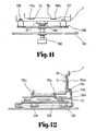
- the actuating lever 119 is turned coounter-clockwise around the pin 120 to have its bent portion l19a fitted on the stepped cam portion 123a. Then, the link 114 and the connecting lever 125 are pulled downwardly of Fig. 10 so that the label guide 124 is pulled toward the cassette 1 whereas the lock levers 110 and 111 are turned counter-clockwise. As a result, the upper end portion 124a of the label guide 124 comes into the backing paper guide groove 15 of the cassette 1, as shown in Fig. 12, to leave a such a gap from the bottom plate 14 as to guide the continuous label web 4. By the counter-clockwise turn of the lock lever 110, moreover, the bent portion 110a is fitted in the notches 7d of the cassette 1.
- the bent portion llla is fitted in the recess 7c of the cassette 1 by the counter-clockwise turn of the lock lever 111.
- the engagement tongues 25 at the lower end of the knob 24 are pushed by the bent portion lllb located at the outer side of the lock lever 111 so that the pressure member 20 enters against the elastic force of the spring 26 thereby to disengage its needle 23 from the backing paper guide groove 15.
- the cassette 1 is reliably locked by the lock levers 110 and 111.
- the not-shown keyboard of the printer 3 is used to input the bar codes which are desired to be printed.
- the continuous label web 4 having the non- printed labels is pulled out of the reel 91 along the guides 93 and 94 through the position detecting mechanism 95 acting as another label guide and is turned along the platen 97 until its leading end is guided into the gap between the label guide 124 and the bottom plate 14 of the cassette 1.
- the heat transfer ink ribbon 100 is also pulled out of the reel 99 and is guided along the guide rollers 101 and 102 and between the thermal head 96 and the label web 4 until its leading end is taken up by the take-up reel 1 105 through the guide rollers 103 and 104.
- a not-shown motor is energized to turn the rotary shaft 108 so that the take-up core 8 starts its rotations through the boss 11 of the cassette 1, in which the head 109 of the shaft 108 is fitted.
- the platen 97, the take-up reel 105 and so on are started to rotate so that the thermal head 96 is operated to start the printing operations of the bar codes in response to the set printing instructions.
- the continuous label web 4 having bar codes heat-transferred to its labels is ' advanced continuously or consecutively intermittently through the label guide 124.
- the label web having left the label guide 124 is advanced along the guide member 137 to the cassette 1 by way of the guide groove 139 extending between the guide member 137 and the peel preventing member 138. Since, at this time, the rotary member 12 of the cassette 1 is opened, as shown in Fig. 5, the label web 4 is guided along the lower side of the label holding portion 13 into the winding space 8c defined by the rotary member 12 and the take-up core 8. Since the winding space 8c is counter-tapered by the inner faces of the flanges 8a and 8a of the take-up core 8, the label web 4 is guided for a while between the flanges 8a and 8a without being dragged by their inner faces.
- the label web 4 is guided along the guide spring 9 to the take-up core 8 until it is thrusted onto the take-up core 8 by the leading end of the guide plate 9. At this time, the label web 4 is in the state in which both its side edges contact with the straight core body 8b at the legs of the flanges 8a and 8a. Since the straight core body 8b has a width slightly smaller than that of the label web 4, this web 4 has both its side edges restricted, when it is pushed onto the take-up core 8 by the guide spring 9, by the core body 8b so that it is wound or taken up sequentially as the take-up core 8 is turned.
- the not-shown motor is stopped to interrupt the supply or let-off of the label web.
- a cutter C interposed between the platen 97 and the label guide 124 may be operated to cut the label web.
- the cassette 1 on which the label web having the bar codes printed is wound in the predetermined quantity is demounted from the printer.
- the actuating lever 119 is turned clockwise, as viewed in Fig. 10, to unlock the cassette 1 from the lock levers 110 and 111, and the label guide 124 is disengaged from the cassette bottom plate 14 to release the cassette 1 from any restriction.
- the cassette 1 can be easily removed if it is manually disengaged from the guide pins 106 and 107.
- Two or three sheets of the labels 6 are peeled from the bottom plate 14 of the removed cassette 1, and the rotary member 12 is returned to the locked state of Fig. 1, .thus finishing the charging operations of the cassette 1 with the labels 6.
- the cassette 1 thus having been charged with the printed labels is attached to the label applicator 2 in the following manners. Specifically, the mounting portions 31 of the cassette 1 are accommodated in the accommodating space 34 of the applicator 2 such that the engagement projections 30 at the leading end of the cassette 1 are held in engagement with the engagement notches 37 of the applicator 2. At this time, the pent-roofs 77, which are formed below the display label fitting recesses 32 of the cassette 1, are placed on the ledges 35 of the applicator 2 so that the cassette 1 is automatically locked by the lock mechanism 67.
- the aforementioned engagement projections 73 drop while turning the lock member 69 counter-clockwise against the biasing force of the spring 68.
- the backing paper 5 is released from being held by the pressure land 22 and the needle 23 of the pressure member 20 so that it is smoothly fed back until it is discharged to the outside of the label applicator 2.
- the push-up plate 60 is retracted to disengage its lower face from the supporting member 62.
- the pressure member 20 is moved down to restore its original position, while pushing down the push-up plate 60 counter-clockwise, by the force of the spring 26, so that the backing paper 5 is held again by the coactions of the pressure land 22 and the needle 23.
- the label web 4 since the label web 4 has its advancing position regulated to a horizontal position, only the backing paper 5 'is .
- the push-up plate 60 abuts against the supporting member 62 to turn the same counter-clockwise because the force of the spring 26 to push down the push-up plate 60 is stronger than the summation of the forces of the springs 64 and 65. Then, the push-u p plate 60 advances sliding on the lower faces of the tongues 25 but not raising the same. As a result, the backing paper 5 is fixed by the pressure member 20 and is not returned to the front by the forward motion of the pawl member 46.
- this pawl member 46 has its advancing pawls 45 disengaged from the cuts 78 of the backing paper 5 and is turned clockwise against the action of the spring 59 to slide on the lower side of the backing paper 5 until it restores its original position, in which it engages again with the cuts 78 of the backing paper 5.
- the demounting button 70 is pushed foward, as shown in Fig. 25. Then, the lock member 69 is turned counter-clockwise to disengage its lower end corner 71 from the engagement projections 73 of the cassette 1, and the rear portion of the cassette 1 is slightly popped up by the spring action of the backing paper holding member 74, which presses the lower side of the backing paper 5 in front of the backing paper guide groove 15, so that the cassette 1 can be easily removed by the single action.
- the label web having its labels printed with the bar codes can be automatically wound over a predetermined length merely by charging the printer with the cassette so that the troublesome work of winding the labels upon the cassette can be eliminated to ensure efficient operations.
- the operation of mounting the cassette in the printer can be conducted by the single action of actuating the actuating lever, but the labels are not peeled off while the label web is being taken up, because the printer is equipped with the peel preventing member. Since the take-up core 8 is formed integrally with the flanges 8a and 8a such that these flanges 8a rotate with the core 8, still moreover, there arises no relative velocity between the continuous label web and the flanges 8a.
- the adhesive having stolen to both the side edges of the label web is neither rubbed nor left alone by the flanges so that the winding and rewinding operations of the label web can be performed remarkably smoothly.
- a small amount of adhesive is left on the straight core body 8b, it establishes slight adhesion of the label web being wound, thus providing an excellent effect that the label web is fixed at the initial stage of the winding operation.
- Figs. 26 to 28 show another embodiment of the present invention, in which the take-up core is omitted but only the.rotary member 12 is mounted in the cassette 1.
- the rotary member 12 is formed into such a hollow frame that it is rotatably borne on the cassette frame 7 through cylindrical lands 12a which are formed to protrude from its right and left side walls.
- the inner circumference of the rotary member 12 is formed with two parallel ridges 140 having a triangular section, which extend all over the circumference from the back of the label holding portion 13.
- There is further formed a slit 12b which extends from the rear end portion of the label holding portion 13 to the circumferentially central portion of the rotary member 12.
- the present second embodiment is not equipped with any take-up means but the rotary member 12.
- the label web 4 When the label web 4 is to be wound or taken up in the present embodiment having the construction thus far described, it is supplied, as shown in Fig. 28, to pass through the guide groove 139 and then to advance from the opening of the raised rotary member 12 into the inside of the rotary member 12.
- the label web 4 advances along the inner circumference of the rotary member 12, while contacting with the ridges 140, until it is curled in an arcuate shape and is gradually taken up.
- the advancing force of the label web 4 is generated by the rotating force of the platen 97, by which the label web 4 is gradually wound in a spiral shape in accordance with its own re g idity and elasticity.
- the present embodiment is not suitable for much winding of the label web 4 because the frictional force between the wound layers becomes stronger than the rigidity of the label web 4 as the winding increases.
- the label web 4 can be automatically wound or taken up by adopting the construction of the present embodiment so long as the printer is equipped with the peel preventing member 138 and the guide member 137.
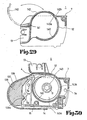
- a cover 142 which is made of a transparent material and which has its one end rotatably borne on a pin 141 in the vicinity of the label holding portion 13, as shown in Fig. 29.
- This cover 142 is formed into such an arcuate shape that it can be fitted in the slit 12b, and is further formed at its free end with a hooking portion 142a which can be hooked by an engagement portion 142b formed at the rotary member 12.
- the ridges 140 are also formed on the inner circumference of the cover 142. If this modified construction is adopted, the inside of the rotary member 12 can be so accessed that the trouble of the label web 4 in the rotary member 12 can be remedied by opening the cover 142.
- Figs. 30 and 31 show a third embodiment of the present invention.
- the rotary member 12 has its circumferential wall formed into about one spiral, as shown in Fig. 30, and a take-up core 143 is disposed in the rotary member 12 and made rotatable with respect to the cassette frame 7, as shown in Fig. 31.
- This take-up core 143 is composed of: two right and left flanges 143a; and straight portions 143b which form the outer circumferential edges of the inner faces of the flanges 143a and which are spaced at a distance slightly smaller than the width of the label web 4.
- a tapered space 143c is so defined by the flanges 143a that it is expanded or counter-tapered gradually in the radially inrward direction.
- the take-up core 143 is formed with the boss 11 which is to be fitted on the rotary shaft of the printer.
- the rotary member-12 is also formed on its inner circumference with the two parall ridges 140 having the triangular section as in the foregoing embodiment.
- the leading end of the label web 4 having been guided through the guide groove 139 is first introduced into the rotary member 12 by the circumferential wall of the rotary member 12 and is then bitten between the straight portions of the flanges 143a of the take-up core 143.
- the flanges 143a are turned by the rotary shaft 108 of the printer so that the label web 4 is instantly taken up.
- the label web 4 is gradually inwardly pulled in a spiral form, while contacting with the ridges 140 formed on the spiral circumferential wall, until it is consecutively forced out of contact with the straight portions 143b.
- the label web can be automatically wound or taken up.
- the label web guided can be forcibly taken up to make unnecessary the spare parts such as the guide spring 9 employed in the first embodiment so that the resistance coming from the pressure of that spring can be accordingly eliminated.
- Figs. 32 and 33 show a fourth embodiment of the present invention, in which a take-up core 144 disposed in the rotary member 12 is not formed with any flange but has its outer circumference wound with a friction member 145 made of rubber or the like.
- a guide member 146 which is made of steel wire or the like and which extends from the inner side of the label holding portion 13 to make about one turn in the rotary member 12 while contacting with that friction member 145.
- the guide member 146 has its leading end providing a free end and its intermediate portion biased to contact with the friction member 145 at all times.
- the label web 4 is guided from the entrance of the rotary member 12 along the guide member 146 and is clamped between the guide member 146 and the friction member 145 until it is automatically taken up on the take-up core 144.
- the guide member 146 has its contacting portion shifted gradually outward. In these ways, the label web can be automatically taken up.
- Figs. 34 and 35 show a fifth embodiment of the present invention, which is different from the fourth embodiment only in that a leaf spring 147 is used as the guide member. Because of large width, the leaf spring 147 has a large contact area with the label web so that it can hold the label web without fail but by an increased frictional force. By this construction, the continuous label web can also be automatically taken up in a reliable manner.
- Figs. 36 to 38 show a sixth embodiment of the present invention, in which the take-up core 147 is formed on its outer circumference with a plurality of needles 148 which are arranged to project from the widthwise central portion thereof and at a predetermined pitch in the circumferential direction. Moreover, there is provided a guide member 149 which has its one end fixed to the label holding portion 13 of the rotary member 12. The guide member 149 is curved about one turn within the rotary member 12 while contacting with the take-up core 147 at its midway. The guide member 149 thus formed is formed, as shown in Fig. 38, into the shape of a leaf spring, and its contacting portion with the take-up core 147 is formed with a slit 149a which extends a predetermined length for allowing the needles 148 to escape thereinto.
- the label web 4 introdued is guided along the guide member 149 to the take-up core 147 and is trapped between the guide member 149 and the take-up core 147, and the needles 148 bite into the backing paper of the label web 4 so that they begin to wind the label web 4 without fail.
- the guide member 149 goes apart from the center as the amount of the label web taken-up increases, because its one end is set free.
- the guide member 149 may be exemplified by two parallel guide members which are prepared by folding back a steel wire.
- Figs. 40 and 41 show a seventh embodiment of the present invention, in which the take-up core 147 is formed on its outer circumference with pins 150 in place of the needles at a predetermined pitch and in which the guide member 149 used is exemplified by such a member as is similar to those shown in Figs. 38 and 39.
- the take-up core 147 used has the construction specified in the above, it is convenient to use the label web 4 which is formed between the adjacent labels with holes 4a or slits 4b at a pitch equal to the pitch P of the pins 150, as shown in Fig. 41. By adopting this construction, too, the label web can be automatically taken up like the sixth embodiment.
- Figs. 42 and 43 show an eighth embodiment of the present invention, in which the rotary member 12 having the cover 142 like the second embodiment and the take-up core 144 formed on its circumference with the friction member shown in Fig. 32 are combined and in which a cantilever guide member 151 is provided as the guide member.
- This guide member 151 is formed, as shown in Fig. 43, into an arcuately curved leaf spring which has its one end fixed on the label holding portion 13 of the rotary member 12 and its other end contacting with the friction member 145.
- the guide member 151 may be exemplified by a steel wire 152, as shown in Fig. 44.
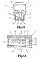
- Figs. 45 to 48 show a ninth embodiment of the present invention, in which a take-up core 153 is made to have a shape different from those of the foregoing embodiments and in which the guide groove is devised I in a different manner.
- the take-up core 153 is equipped at a predetermined spacing with a plurality of vanes 154, which have such sections as form radially arranged spiral curves, and is turned in the curved direction of the vanes 154, as indicated at arrow in Fig. 46.
- the guide groove portion forming the peel preventing member has such a construction as will be described in the following.
- the guide groove is defined by both a stationary guide member 155, which is made separate but extend from the label guide 124, and a movable guide member 156.
- the stationary guide member 155 is formed as a whole into an arc of one-quarter circle having a C-shaped cross-section and at its portion with a curved portion 155a which is to be fitted in the notches 7d formed in the cassette frame 7 at the leading end portion of the cassette 1.
- the movable guide member 156 is formed into an arcuate gutter having a C-shaped cross-section so that it is slidably fitted on the outer sides of the stationary guide member 155.
- the movable guide member 156 rotatably supports a roller 157 at its leading end portion. Moreover, the movable guide member 156 is fixed on a supporting sector 158 which has its pivot rotatably borne on the base frame 90 or the bracket 136. Still morover, a coil spring 162 is mounted under tension between a pin 160, which is anchored in the vicinity of the pin 159 of the supporting sector 158,-and a pin 161 which is anchored at the stationary guide member 155.
- the movable guide member 156 is turned clockwise, as viewed in Fig. 46, on the pin 159 so that the guide roller 157 is brought into contact with the circumference of the take-up core 153.
- the spring 162 biases the supporting sector 158 to rotate clockwise because it is positioned over the pin 159 at the side of the cassette 1.
- the guide roller 157 is held in contact with the circumference of the take-up core 153.
- the label web 4 having been guided by the guide members 155 and 156 advances into the gap between the vanes 154 of the take-up core 153 so that its leading end is folded in the form of a letter "V" by the vanes 154 as the take-up core 153 rotates.
- the label web 4 is forcibly wound on the take-up core 153 by the frictional force which is established between its folded portion and the vane 154.
- the movable guide member 156 is turned counter-clockwise of the drawing together with the supporting sector 158 through the guide roller 157 contacting with the label web 4.
- the spring 162 passes over the pin 159, i.e., the dead center
- the movable guide member 156 is abruptly turned counter-clockwise by the tension of the spring 162.
- the turning limit of the supporting sector 158, i.e., the movable guide member 156 is regulated by both an arcuate guide groove 158a, which is formed in the supporting sector 158, and a guide pin 163 which is anchored at the printer to extend through the guide groove 158a.
- the label web 4 can be automatically taken up.
- this can be detected by means of a limit switch so that the winding operation can be promptly interrupted.
- the motor can be energized only when it is necessary so that the electric power consumption can be reduced.
- the label web having its labels printed with the bar codes can be automatically wound while automating the setting of the backing paper in the bottom of the cassette.
- automating the setting of the backing paper in the bottom of the cassette it is possible to completely automate the label winding and mounting operation which has bottlenecked the development of the portable label applying system.
- cassette mounting and demouting mechanism can be operated by the single action of actuating the actuating lever so that the mounting and demounting operations are simplified to eliminate the troubles.
- the labels are not peeled but can be taken up completely automatically when the label web is to be automatically wound.
- Fig. 49 is a righthand side elevation of the printer 3, from which the lef-off reel of the label web 4 in its rolled form is omitted.
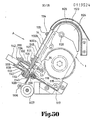
- Numeral 1100 appearing in Fig. 49 indicates the frame of the printer 3, and numeral 1101 indicates a rear cover. This rear cover 1101 is formed generally at its center with an entrance 1102 for receiving therethrough the label web 4 which is unrolled or let off the let-off reel.
- the label web 4 having been guided by a guide member 1103 at the label entrance 1102 is introduced into the printer 3 and is guided by a guide roller 1104to advance through.
- a position detecting mechanism 1105 in which the position of the label is detected by detecting means such as a photo-sensor.
- the label position having detected by the mechanism 1105 advances between a thermal head 1106 of heat transfer type and a platen 1107, both of which construct together a thermal printer.
- the thermal head 1106 is attached to the free end side of an arm 1108 and is so constructed that it is urged toward the platen 1107 by the action of a not-shown spring.
- reference numeral 1109 indicates a let-off reel on which a heat transfer ink ribbon 1110 is wound.
- This ink ribbon 1110 unwound from the reel 1109 is guided through a guide roller 1111 to the thermal head 1106, at which it is superposed upon the label web 4 before print so that predetermined bar codes are transferred onto the labels by the action of the thermal head1106.
- the ink ribbon is guided by a guide pin 1112 until it is taken up on a take-up reel 1113.
- the label web 4 having its labels bearing the transferred bar codes is turned at the platen 1107 until it is guided into the cassette 1 which is removably mounted on the frame 1100.
- the mounting mechanism1114 for mounting the cassette 1 will be described in detail with reference to Figs. 49 to 55.
- a cassette guide member 1117 which is formed with two guide faces 1115 and 1116 intersecting at a right angle for guiding the two sides of the take-up cassette 1.
- the guide face 1116 has its lefthand end depending obliquely downward to the vicinity of the platen 1107 and the thermal head1106 thereby to provide a guide portion for the label web 4.
- the stationary knife 1119 of a cutter mechanism 1118 which will be described hereinafter.
- a rotary shaft '121 As shown in Fig. 53, which is to be fitted in the boss 11 of the take-u p core 8 of the cassette 1.
- a guide member 1123 which draws a large arcuate curve. This guide member 1123 is fixed to the frame 1100 and has its leading end leading to the vicinity of the upper end of the opening of the leading end of the frame 7 of the cassette 1. Inside of the guide member 1123, there is disposed a peel preventing member 1124.
- This member 1124 is formed into such a block as has its side edge curved to profile the guide member 1123 to define a guide groove 1125 inbetween. In order to clean this guide groove 1125 or to prevent the same from being jammed with the label or labels, incidentally, it is preferred to make removable at least one of the guide member 1123 and the peel preventing member 1124 .
- the other side edge of this peel preventing memberfl24 is shaped to complement the side edge of the leading end side of the cassette 1 and is formed in its midway with a pin 1126 which is anchored at the frame 1100 and is to be fitted in the notches 7a, formed in the leading end of the cassette 1. The reason why the peel preventing member 1124 is so highly curved is intended to prevent the labels from being peeled off their backing paper if the label web is guided in an acutely bent shape.
- a supporting member 1128 having a shape of letter "C" is fixed to the printer frame 1100.
- a hinging pin 1129 is inserted through the supporting member 1128.
- Doors 1130a and 1130b acting together as the pressure releasing member 1127 are fixedly integrated by means of stop screws 1131 and 1131.
- the door 1130b has its lefthand end so hinged that it can turn on the pin 1129 in the direction of arrow of Fig. 52. As better seen from Figs.
- the doorfl30b has its one end bent at a right angle to form a mounting portion 1132 and is fastened by means of screwsf134 to that cutter box 1133 of the cutter mechanism 118, which is fixed to the door 1130a.
- the door 1130a has its one end chamferred into a sloped face 1135.
- Numeral 1147 indicates an aperture which is formed in the door 1130a.
- Indicated at numeral 1136 is a torsion spring for biasing the doors 1130a and 1130b counter-clockwise on the hinging pin 1129.
- the door 1130a is desirably made of a transparent plastic material so that the passage of the label web 4 can be confirmed therethrough.
- an engagement spring 1137 acts to prevent the doors 1130a and 1130b from being erroneously opened.
- Indicated at numeral 1138 is a stopper for preventing any permanent strain from occuring in the engagement spring1137 due to the turn of the spring 1137 more than necessary when the doors 1130a and 1130b are opened by turning the engagement spring 1137 clockwise.
- the cutter mechanism 1118 for cutting the label web 4 has such a construction as will be described with reference to Fig. 54. Specifically, the cutter mechanism 1118 is constructed to cut the label web 4 by the coaction of the aforementioned stationary knife 1119 and a movable knife or cutter 1139. This cutter4139 is enabled to turn on the hinging pin 1129. In the cutter box 1133, moreover, there are mounted both a tension spring 1140 for biasing the cutter 1139 counter-clockwise and a leaf spring 1141 for elastically urging the cutter 1139 to the stationary knife 1119 so that the former 1139 may come into contact with the latter 1119 thereby to ensure their cutting operations.
- Indicated at numeral 1142 is a button for manually depressing the cutter 1139 against the biasing force of the tension spring 1140.
- Indicated at numeral f148 is a stopper which is made integral with the cutter 1139 for providing the upper limit of the same 1139.
- Reference numeral 1143 appearing in Fig.50 indicates a label guide which is fastened together with the cutter box 1133 to the door 1130a by means of screws 1144. Between the label guide 1143 and the aforementioned guide portion 1120, there is formed such a small gap as allows the label web 4 to pass therethrough.
- numeral 1146 indicates a keyboard for inputting necessary data to the printer 3.
- the engagement spring 1137 When the engagement spring 1137 is first turned clockwise, it is released from the engagement with the door 1130a. At this time, the doors 1130a and 1130b are popped up counter-clockwise by the biasing force of the spring 1136. Next, the empty take-up cassette 1 is mounted along the guide faces 1115 and 1116 of the guide member 1117. Then, the boss 11 of the cassette 1 is brought into engagement of the head 1122 of the rotary shaft 1121. At the same time, the notches 7a of the cassette 1 are brought into engagement with the pin 126.
- the rotary member 12 of the take-up cassette 1 is turned clockwise, as shown in Fig. 49, until it is opened. If the cassette 1 is to be mounted with the rotary member 12 being left closed, the label holding portion 13 of the rotary member 12 comes into abutment against the pin1126 and the peel preventing member 1124 so that the cassette 1 cannot be mounted.
- the doors 1130a and 1130b are turned clockwise, they are retained by the engagement spring 1137 so that they are not carelessly opened.
- the engagement tongues 25 at the lower ends of the knobs 24 of the take-up cassette 1 are pressed by the pressure face 1145 of the inner wall of the door 1130a.
- the pressure member 20 is retracted against the elastic force of the spring 26 so that the needle 23 is brought apart from the backing paper guide groove 15.
- the backing paper holding mechanism 18 is released by the pressure releasing member 1127. This release raises no obstruction to the passage of the label web 4 between the door 1130a and the bottom plate 14 of the cassette 1.
- the bar codes to be printed are inputted by the use of the keyboard 1146 of the printer 3.
- the label web 4 having the unprinted labels adhered is pulled out of the not-shown let-off reel.
- This label web 4 is threaded along the guide member 1103 and the guide roller 1104 into the position detecting mechanism 105 and is so turned along the platen 1107 that its leading end is threaded into the gap between the guide portion 120 and the label guide 1143 until it is introduced into the gap between the door 1130a and the bottom plate 114.
- the heat transfer ink ribbon 1110 is also pulled out of the reel 1109 and is threaded along the guide roller 1111 and between the thermal head 106 and the label web 4 until its leading end is taken up by the take-up reel 1113 through the guide pin 1112.
- a not-shown motor is energized to turn the rotary shaft 1121 so that the take-up core 8 starts its rotations through the boss 11 of the cassette 1, in which the head4122 of the shaft 1121 is fitted.
- the platen 1107, the take-up reel 1113 and so on are started to rotate so that the thermal head 1106 is operated to start the printing operations of the bar codes in response to the set printing instructions.
- the continuous label web 4 having bar codes heat-transferred to its labels is advanced continuously or consecutively intermittently through the backing paper guide groove 15 between the principal 1130a and the bottom plate 14 of the cassette 1.
- the label web having left the backing paper guide groove 14 is advanced along the guide member 1123 to the cassette 1 by way of the guide groove 125 extending between the guide member 123 and the peel preventing member 1124. Since, at this time, the torary member 12 of the cassette 1 is opened, as shown in Figs. 5 and 49, the label web 4 is guided along the lower side of the label holding portion 13 into the winding space 8c defined by the rotary member 12 and the take-up core 8.
- the label web 4 Since the winding space 8c is counter-tapered by the inner faces of the flanges 8a and 8a of the take-up core 8 , the label web 4 is guided for a while between the flanges 8a and 8a without being dragged by their inner faces. Before long, the label web 4 is guided along the guide spring 9 to the take-up core 8 until it is thrusted onto the take-up core 8 by the leading end of the guide plate 9. At this time, the label web 4 is in the state in which both its side edges contact with the straight core body-8b at the legs of the flanges 8a and 8a.
- the straight core body 8b has a width slightly smaller than that of the label web 4, this web 4 has both its side edges restricted, when it is pushed onto the take-up core 8 by the guide spring 9, by the core body 8b so that it is wound or taken up sequentially as the take-up core 8 is turned.
- the not-shown motor is stopped to interrupt the supply or let-off of the label web.
- the tton 1142 of the cutter mechanism 118 is depressed. Then, the cutter 1139 is turned clockwise against the biasing force of the tension spring 1140. And, the cutter 1139 passes through the aperture 1147 formed in the door 1130a and drops, while contacting with the stationary knife 1119, to cut the label web 4.
- the cassette 1, on which the label web 4 having the bar codes printed is wound in the predetermined quantity is demounted from the mounting device 1114 of the printer 3.
- the engagement spring 1137 is turned clockwise like the mounting operation to pop up the doors 1130a and 1130b counter-clockwise, and the label web 4 may be pulled out of the guide groove 1125 by grasping the cassette 1.
- the label web 4 left in the guide groove 1125 is in the state to protrude in a semicircular shape from the cassette 1.
- the boss 11 of the cassette 1 is turned by fingers to take up the extension of the label web 4 on the take-up core 8.
- the rotary member 12 is returned to the locked state shown in Fig. 1.
- the charge of the cassette with the label web 4 is completed.
- the description of the foregoing embodiment has been made such that the cassette 1 is neither mounted in nor demounted from the mounting device 1114 of the printer 3 before the doorsf130a andf130b are opened.
- the mounting and demounting operations can be conducted even with the doors 1130a and 1130b being left closed.
- the engagement tongues 25 at the lower ends of the knobs 24 are pressed by the sloped face 1135 when the cassette 1 is mounted along the guide faces4115 and 1116 of the guide member 1117, until the tongues 25 come into contact with the pressure face 1145 on the inner wall of the door 1130a so that the needle 23 comes apart from the backing paper guide groove 15, as has been described hereinbefore.
- the foregoing embodiment is constructed such that the guide member 1117 having the guide faces 1115 and 1116 is used as the guide means when the cassette 1 is mounted in the mounting device 1114.
- the present invention should not be limited to the aforementioned embodiment but may be modified such that the cassette 1 is formed with at least two through holes whereas the mounting device 1114 is formed with two pins which are anchored at the positions corresponding to those through holes so that the cassette 1 may be guided by both the through holes and the pins.
- the take-up cassette 1 is to be mounted in or demounted from the label applicator 2.
- This case will be described simply and schematically because it is not the gist of the present invention but has been described in detail in the specification of the aforementioned Japanese Patent Laid-Open No. 56 - 210021.
- the mounting portions 31 of the cassette 1 are accommodated in the accommodating space 34 of the applicator 2 such that the engagement projections 30 at the leading end , of the cassette 1 are held in engagement with the engagement notches 37 of the applicator 2.
- the pent-roofs 77of the cassette 1 are placed on the ledges 35 of the applicator 2 so that the cassette 1 is automatically locked by the lock mechanism 67.
- the lower end corner 71 of the lock member 69 comes into engagement with and is locked by the engagement projections 73. If the hand lever 41 is then squeezed, the holding frame 47 is horizontally moved back along the guide grooves 57 through the first, second and third links 48, 49 and 50. During this horizontal movement, the advancing pawls 45 of the pawl member 46 engage with the cuts 78, which are formed at a predetermined interval in the backing paper 5, as shown in Fig. 17, to advance the backing paper 5, and the push-up plate 60 is also moved to push up the engagement tongues 25 of the presssure member 20.
- the backing paper 5 is released from being held by the pressure land 22 and the needle 23 of the pressure member 20 so that it is smoothly fed back until it is discharged to the outside of the label applicator 2.
- the hand lever 41 is further squeezed, as shown in Fig. 19, the push-up plate 60 is retracted to disengage its lower face from the supporting member 62.
- the pressure member 20 is moved down to restore its original position so that the backing paper 5 is held again by the coactions of the pressure land 2-2 and the needle 23.
- the push-up plate 60 is set to advance while sliding on the lower faces of the tongues 25 but not raising the same.
- the backing paper 5 is fixed by the pressure member 20 and is not returned to the front by the forward motion of the pawl member 46.
- this pawl member 46 has its advancing pawls 45 disengaged from the cuts 78 of the backing paper 5 to slide on the lower side of the backing paper 5 until it restores its original position, in which it engages again with the cuts-78 of the backing paper 5.
- the demounting button 70 is pushed forward. Then, the lock member 69 is turned counter-clockwise to disengage its lower end corner 71 from the engagement projections 73 of the cassette 1, and the rear portion of the cassette 1 is slightly popped up by the spring action of the backing paper holding member 74, which presses the lower side of the backing paper 5 in front of the backing paper guide groove 15, so that the cassette 1 can be easily removed by the single action.
- the label web having its labels printed with the bar codes can be automatically wound over a predetermined length merely by charging the printer with the cassette so that the troublesome work of winding the labels upon the cassette can be eliminated to ensure efficient operations.
- the operation of mounting the cassette in the printer can be conducted by the single action of actuating the actuating lever, but the labels are not peeled off while the label web is being taken up, because the printer is equipped with the peel preventing member.
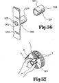
- Figs.56 to 58 show another example of use of the present invention.
- the take-up cassette 1 and the label applicator 2 are not used, but the printed labels 6 are manually applied to the commodities.
- the example is constructed of an adaptor 1200 and a take-up tool 1201, as shown in Fig. 56.
- the adaptor 1200 is constructed such that a cylindrical shaft 1203 protrudes from the center of a rectangular base plate 1202.
- the shaft 1203 is formed with a blind bore 1205 which extends from the base plate 1202 and which has grooves 1204.
- These grooves 1204 and the blind boref205 are so shaped as can fit therein the head 1122 of the rotary shaft 1121 of the printer 3.
- the axial length of the shaft 1203 is made larger than the width of the label web 4.
- the take-up tool 1201 is formed into such a shape as has a generally C-shaped section having a slit 1206 by axially cutting the outer circumference of a cylinder.
- the take-up tool 201 is made of a flexible material such as metal or plastics.
- the take-up tool 1201 is made to have an internal diameter slightly smaller than the external diameter of the shaft 1203 and to have an axial length equal to that of the shaftf203.
- the adaptor 1200 is fitted on the head 1122 of the rotary shaftf121 of the.printer 3.
- the keyboard 1146 of the printer 3 is used to input the bar codes to be printed.
- the continuous label web 4 is printed with the bar codes, and the leading end of the printed label web 4 is threaded through the gap formed between the guide portion 120 and the label guide 1143.
- the keyboard 1146 is used to temporarily interrupt the operations of the printer 3.
- the take-up tool 1201 is mounted on the outer circumference of the shaft 1203 by expanding its internal diameter. Then, the take-up tool 1201 is held in close contact upon the outer circumference of the shaft 1203 by its own flexibility. Thus, the leading end portion of the label web 4 is inserted into the inside of one end portion 1207 of the take-up tool 1201. As a result, that leading end portion is clamped and held between the take-up tool 1201 and the shaftf203. If, in this state, the keyboard 1146 of the printer 3 is used to restart the printer 3, the printed label web 4 is let off, and the adaptor1200 is turned clockwise so that the label web 4 is taken up on the take-up tool 1201.
- the cutter mechanism 1118 is actuated to cut the trailing end of the label web 4.
- the take-up tool 1201 is removed from the shaft 1203. More specifically, the end portion of the take-up tool 1201 at the side where the label web 4 is not wound is gripped and pulled sideway. Then, the take-up toolf201 is slid on the outer circumference of the shaft 1203 so that it is removed from the. shaftf203 together with the printed label web 4 in the rolled shape. If the outer circumference of the take-up tool 1201 is pinched by the fingers, as shown in Fig.
- the tool 1201 is warped inwardly so that only the tool 1201 can be pulled out of the rolled label web 4 if it is pulled to the side of the Operator.
- the take-up tool 1201 thus removed can be reused for taking up the subsequent label web 4 if it is set on the adaptor 1200 of the printer 3 likewise the procedures explained in the above.
- the aforementioned rolled label web 4 itself is brought to a commodity counter or warehouse, in which the labels 6 are manually peeled from the backing paper 5 and applied to the target commodities.
- the using example of the present invention is composed of the adaptor 1200 and the take-up tool 1201 both having the simple constructions.
- the label web 4 can be simply taken up and taken out from the printer 3 by the single action after the taking-up operation.
- the take-up tool 1201 can be simply extracted by its own flexibility from the rolled label web 4.
- the present using example need not use the take-up cassette 1 and the label applicator 2 of the foregoing embodiment.
- the portable label applying system becomes so inexpensive that it can be employed at a reasonable cost even by stores which handle a relatively small number of labels.
- the label web having its labels printed with the bar codes can be automatically wound while automating the setting of the backing paper in the bottom of the cassette.
- the label web having been wound up can be cut to have a predetermined length, thus making it possible to provide an automatic label winding and charging device which has a small number of parts and a simple construction.
Landscapes
- Labeling Devices (AREA)
Applications Claiming Priority (4)
| Application Number | Priority Date | Filing Date | Title |
|---|---|---|---|
| JP32913/83 | 1983-03-02 | ||
| JP58032913A JPS59163139A (ja) | 1983-03-02 | 1983-03-02 | ラベル自動巻取装着装置 |
| JP1983079738U JPS59184666U (ja) | 1983-05-28 | 1983-05-28 | 巻取カセットへのラベル自動巻取装着装置 |
| JP79738/83U | 1983-05-28 |
Publications (3)
| Publication Number | Publication Date |
|---|---|
| EP0119524A2 true EP0119524A2 (de) | 1984-09-26 |
| EP0119524A3 EP0119524A3 (en) | 1985-11-21 |
| EP0119524B1 EP0119524B1 (de) | 1989-07-12 |
Family
ID=26371515
Family Applications (1)
| Application Number | Title | Priority Date | Filing Date |
|---|---|---|---|
| EP19840102194 Expired EP0119524B1 (de) | 1983-03-02 | 1984-03-01 | Automatische Etikettenaufroll- und -ladevorrichtung |
Country Status (2)
| Country | Link |
|---|---|
| EP (1) | EP0119524B1 (de) |
| DE (2) | DE3478918D1 (de) |
Cited By (5)
| Publication number | Priority date | Publication date | Assignee | Title |
|---|---|---|---|---|
| EP0133932B1 (de) * | 1983-08-24 | 1987-05-20 | Kabushiki Kaisha Sato | Automatischer Etikettenwickler |
| GB2254839A (en) * | 1990-04-28 | 1992-10-21 | Osaka Sealing Label Print | Label dispenser |
| CN108190574A (zh) * | 2017-12-26 | 2018-06-22 | 天津成理能顺科技有限公司 | 一种高效商标标签带卷带机 |
| CN110188860A (zh) * | 2019-05-25 | 2019-08-30 | 嘉兴美宝数码科技有限公司 | 一种电子标签复合设备 |
| CN117429936A (zh) * | 2023-12-20 | 2024-01-23 | 广州复雅机械设备有限公司 | 衬纸卷放纸机 |
Family Cites Families (3)
| Publication number | Priority date | Publication date | Assignee | Title |
|---|---|---|---|---|
| US3061836A (en) * | 1961-04-03 | 1962-11-06 | James G Mackechnie | Improvements in ticket feeding apparatus for hand stapling machines |
| JPS57153844A (en) * | 1981-03-05 | 1982-09-22 | Sato Co Ltd | Device for printing and pasting label |
| US4578140A (en) * | 1981-07-21 | 1986-03-25 | Teraoka Seiko Co., Ltd. | Cassette type labeler and cassette case |
-
1984
- 1984-03-01 DE DE8484102194T patent/DE3478918D1/de not_active Expired
- 1984-03-01 DE DE1984102194 patent/DE119524T1/de active Pending
- 1984-03-01 EP EP19840102194 patent/EP0119524B1/de not_active Expired
Cited By (7)
| Publication number | Priority date | Publication date | Assignee | Title |
|---|---|---|---|---|
| EP0133932B1 (de) * | 1983-08-24 | 1987-05-20 | Kabushiki Kaisha Sato | Automatischer Etikettenwickler |
| GB2254839A (en) * | 1990-04-28 | 1992-10-21 | Osaka Sealing Label Print | Label dispenser |
| CN108190574A (zh) * | 2017-12-26 | 2018-06-22 | 天津成理能顺科技有限公司 | 一种高效商标标签带卷带机 |
| CN110188860A (zh) * | 2019-05-25 | 2019-08-30 | 嘉兴美宝数码科技有限公司 | 一种电子标签复合设备 |
| CN110188860B (zh) * | 2019-05-25 | 2022-05-20 | 嘉兴美宝数码科技有限公司 | 一种电子标签复合设备 |
| CN117429936A (zh) * | 2023-12-20 | 2024-01-23 | 广州复雅机械设备有限公司 | 衬纸卷放纸机 |
| CN117429936B (zh) * | 2023-12-20 | 2024-03-29 | 广州复雅机械设备有限公司 | 衬纸卷放纸机 |
Also Published As
| Publication number | Publication date |
|---|---|
| EP0119524A3 (en) | 1985-11-21 |
| DE3478918D1 (en) | 1989-08-17 |
| DE119524T1 (de) | 1985-02-14 |
| EP0119524B1 (de) | 1989-07-12 |
Similar Documents
| Publication | Publication Date | Title |
|---|---|---|
| US4440592A (en) | Portable type label applying apparatus | |
| US4505773A (en) | Automatic label winding and charging device | |
| EP0083081A2 (de) | Etikettenabziehanlage | |
| EP0902744B1 (de) | Thermischer drucker mit unter federspannung stehender rolle schreibwalze | |
| US5943085A (en) | Image recording device having detachable web roll cassette | |
| US4578140A (en) | Cassette type labeler and cassette case | |
| JPS5839703B2 (ja) | ラベルテンプキ | |
| US7284922B2 (en) | Label printer | |
| EP0083070B1 (de) | Tragbare Etikettiermaschine | |
| US4552610A (en) | Automatic label winding and charging device for printers | |
| EP0119524B1 (de) | Automatische Etikettenaufroll- und -ladevorrichtung | |
| US4451323A (en) | Portable label applying machine | |
| DE3781601T2 (de) | Elektronisches handetikettiergeraet. | |
| US4498950A (en) | Portable label applying machine | |
| EP0133932B1 (de) | Automatischer Etikettenwickler | |
| US4257326A (en) | Label positioning mechanism for a label printing machine | |
| JPS6251815B2 (de) | ||
| JP3012208B2 (ja) | 携帯型プリンタ | |
| CA2139982A1 (en) | Tape feeding, cutting and ejecting apparatus for a mailing machine | |
| JPH0123384B2 (de) | ||
| JP7064748B2 (ja) | ラベル発行装置 | |
| JPH043913B2 (de) | ||
| EP1619034B1 (de) | Etikettendrucker mit einem Etikettenabziehmechanismus | |
| JP3570003B2 (ja) | 長尺状部材収納ケース | |
| JP3780613B2 (ja) | ウエッブロール収納カセット |
Legal Events
| Date | Code | Title | Description |
|---|---|---|---|
| PUAI | Public reference made under article 153(3) epc to a published international application that has entered the european phase |
Free format text: ORIGINAL CODE: 0009012 |
|
| AK | Designated contracting states |
Designated state(s): DE FR GB SE |
|
| EL | Fr: translation of claims filed | ||
| DET | De: translation of patent claims | ||
| PUAL | Search report despatched |
Free format text: ORIGINAL CODE: 0009013 |
|
| AK | Designated contracting states |
Designated state(s): DE FR GB SE |
|
| 17P | Request for examination filed |
Effective date: 19860515 |
|
| 17Q | First examination report despatched |
Effective date: 19861210 |
|
| GRAA | (expected) grant |
Free format text: ORIGINAL CODE: 0009210 |
|
| AK | Designated contracting states |
Kind code of ref document: B1 Designated state(s): DE FR GB SE |
|
| REF | Corresponds to: |
Ref document number: 3478918 Country of ref document: DE Date of ref document: 19890817 |
|
| ET | Fr: translation filed | ||
| PLBE | No opposition filed within time limit |
Free format text: ORIGINAL CODE: 0009261 |
|
| STAA | Information on the status of an ep patent application or granted ep patent |
Free format text: STATUS: NO OPPOSITION FILED WITHIN TIME LIMIT |
|
| 26N | No opposition filed | ||
| EAL | Se: european patent in force in sweden |
Ref document number: 84102194.2 |
|
| REG | Reference to a national code |
Ref country code: GB Ref legal event code: IF02 |
|
| PGFP | Annual fee paid to national office [announced via postgrant information from national office to epo] |
Ref country code: GB Payment date: 20030312 Year of fee payment: 20 |
|
| PGFP | Annual fee paid to national office [announced via postgrant information from national office to epo] |
Ref country code: FR Payment date: 20030320 Year of fee payment: 20 |
|
| PGFP | Annual fee paid to national office [announced via postgrant information from national office to epo] |
Ref country code: SE Payment date: 20030325 Year of fee payment: 20 |
|
| PGFP | Annual fee paid to national office [announced via postgrant information from national office to epo] |
Ref country code: DE Payment date: 20030429 Year of fee payment: 20 |
|
| PG25 | Lapsed in a contracting state [announced via postgrant information from national office to epo] |
Ref country code: GB Free format text: LAPSE BECAUSE OF EXPIRATION OF PROTECTION Effective date: 20040229 |
|
| REG | Reference to a national code |
Ref country code: GB Ref legal event code: PE20 |
|
| EUG | Se: european patent has lapsed |