EP0119562A2 - Chirurgisches Spül- und Absauggerät - Google Patents
Chirurgisches Spül- und Absauggerät Download PDFInfo
- Publication number
- EP0119562A2 EP0119562A2 EP84102576A EP84102576A EP0119562A2 EP 0119562 A2 EP0119562 A2 EP 0119562A2 EP 84102576 A EP84102576 A EP 84102576A EP 84102576 A EP84102576 A EP 84102576A EP 0119562 A2 EP0119562 A2 EP 0119562A2
- Authority
- EP
- European Patent Office
- Prior art keywords
- piston
- barrel
- fluid
- implement according
- surgical implement
- Prior art date
- Legal status (The legal status is an assumption and is not a legal conclusion. Google has not performed a legal analysis and makes no representation as to the accuracy of the status listed.)
- Granted
Links
Images
Classifications
-
- A—HUMAN NECESSITIES
- A61—MEDICAL OR VETERINARY SCIENCE; HYGIENE
- A61M—DEVICES FOR INTRODUCING MEDIA INTO, OR ONTO, THE BODY; DEVICES FOR TRANSDUCING BODY MEDIA OR FOR TAKING MEDIA FROM THE BODY; DEVICES FOR PRODUCING OR ENDING SLEEP OR STUPOR
- A61M3/00—Medical syringes, e.g. enemata; Irrigators
- A61M3/02—Enemata; Irrigators
- A61M3/0229—Devices operating in a closed circuit, i.e. recycling the irrigating fluid
-
- A—HUMAN NECESSITIES
- A61—MEDICAL OR VETERINARY SCIENCE; HYGIENE
- A61M—DEVICES FOR INTRODUCING MEDIA INTO, OR ONTO, THE BODY; DEVICES FOR TRANSDUCING BODY MEDIA OR FOR TAKING MEDIA FROM THE BODY; DEVICES FOR PRODUCING OR ENDING SLEEP OR STUPOR
- A61M3/00—Medical syringes, e.g. enemata; Irrigators
- A61M3/02—Enemata; Irrigators
- A61M3/0233—Enemata; Irrigators characterised by liquid supply means, e.g. from pressurised reservoirs
- A61M3/0254—Enemata; Irrigators characterised by liquid supply means, e.g. from pressurised reservoirs the liquid being pumped
- A61M3/0262—Enemata; Irrigators characterised by liquid supply means, e.g. from pressurised reservoirs the liquid being pumped manually, e.g. by squeezing a bulb
Definitions
- This invention relates to a surgical implement comprising an irrigator/evacuator primarily but not exclusively intended for use in connection with urological surgery, for example prostatic surgery.
- tissue or other fragments In some surgical operations it is necessary to remove tissue or other fragments from the bladder using a technique which involves repeatedly forcing water or other suitable fluid into the bladder and then extracting such fluid whilst separating entrained tissue or other matter to prevent its being reintroduced.
- the object of the invention is primarily to provide an implement of simplified design which works as efficiently as known implements, but can be manufactured sufficiently economically for it to be used only once and then discarded.
- the present invention resides in an implement for the purpose described above, which comprises a reservoir vessel for an irrigation fluid, a double-acting manually operable pump connected to said vessel and having an outlet opening whereby said fluid may be displaced outwardly and withdrawn inwardly through said opening, and in said pump a member which is displaceable during outward displacement of said fluid into a position in which it effectively restrains passage of pieces of tissue carried by said fluid in the direction towards said opening whilst allowing substantially unrestricted flow of said fluid, and which is displaceable during inward withdrawal of the fluid into a position in which it allows free passage of said fluid and pieces of tissue in the direction away from said opening.
- the pump may comprise a barrel having said opening at one end, with said reservoir vessel connected to the barrel by a side tube a point near the outlet opening.
- a compressible bulb may be provided at the end of the barrel remote from said opening.
- a manually operable piston may be provided for this purpose.
- the displaceable member preferably comprises a free piston loosely received in the barrel so as to move along the barrel in response to fluid flow.
- said piston In the first said position, said piston may be disposed at least partially between the side tube and said outlet opening so as partially to obstruct said barrel and thereby effectively prevent passage of pieces of tissue towards said opening.
- the piston in the first said position the piston also partially obstructs the mouth of the side tube so as effectively to prevent passage of pieces of tissue outwardly from the side tube.
- the piston In the second said position the piston may be disposed so that said side tube is at least partially unobstructed and both fluid and pieces of tissue entrained therein may flow without obstruction from said outlet and into to said side tube.
- the implement may be made of any suitable plastics material and can conveniently be supplied in a sterilised pack so as to be immediately available for use. Following such use, the implement may then be discarded.
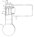
- the implement comprises a manually operable pump which includes a tube or barrel 10 having an outlet nozzle II at one end thereof, preferably at an eccentric position.
- the other end of the barrel 10 is closed by means of a conventional compressible bulb 12.
- a side tube 13 near the nozzle end of the barrel connects with a bottle or reservoir 14.
- a free piston 15 is located within the barrel 10 and is so dimensioned as to have a significant clearance with respect to the internal wall of the barrel.
- the piston is conveniently of a known type which includes a transverse disc 16 with several radially arranged flat fins 17 on the side thereof remote from the nozzle II. Additionally, the disc 16 carries a flat abutment member 18 spaced from the side thereof presented towards the nozzle and of transverse dimensions less than those of the disc 16.
- the implement In use, the implement is entirely filled with water or other suitable irrigation fluid.
- water When the bulb 12 is squeezed, water is displaced outwardly through the nozzle II.
- the water flow causes the piston 15 to move up to the nozzle end of the barrel 10, and the abutment member 18 maintains a predetermined minimum spacing between the disc 16 and the opening 19 at the mouth of the nozzle, so that the flow of water is effectively unobstructed.
- the clearance between the disc 16 and the inner face of the barrel 10 is such as to allow effectively unrestricted flow of water towards the nozzle II.
- the piston 15 When pressure on the bulb 12 is released, water is drawn back into the barrel through the nozzle II, and the piston 15 is thereby displaced towards the bulb.
- the end 12a of the bulb within the tube may serve as an abutment which is engaged by the fins 17 to limit withdrawal of the piston to a position in which the mouth of the side tube is effectively unobstructed without being removed entirely from the mouth.
- the barrel 10 may be formed with a shoulder or constriction which affords an abutment for this purpose. Water drawn in through the nozzle I tends to impinge on the piston 16, and by virtue of the off-centre location of the nozzle, the water tends to swirl downwardly towards the mouth of the side tube 13 leading to the reservoir 14.
- the nozzle is so dimensioned as to enable pieces of tissue having a length of typically 2 to 3 centimetres and a thickness of some 2 to 3 millimetres to pass through. Typically, the internal diameter of the nozzle may be about 5 millimetres. Such pieces of tissue tend to pass into the reservoir 14 by virtue of the swirling action described above, together with gravitational separation effects and become trapped there.
- a bulb 12 as the means for displacing water from the implement
- an additional, close fitting piston within the barrel 11, in the manner of a syringe.
- Such additional piston could be entirely separate from the piston 15, which thus would still be a free piston, but alternatively such close fitting piston could be formed integrally with the piston 15, or otherwise rigidly connected thereto so that the two move together.
- such a close fitting piston could be operated by means of a lever or trigger mounted pivotally in a pistol-type hand grip provided at the end of the barrel.
- the illustrated embodiment can be manufactured simply and economically as a moulding of plastics material, and can make use of a standard compression bulb 12 and a piston 15 which may also be of standard form, as used in the manufacture of a syringe, for example. It is easy to sterilise and light in weight so that it can be supplied, ready for use, in a sterile pack and then be discarded after use.
- the side tube may terminate, for example, in a threaded collar adapted to receive releasably a bottle of glass or plastics material having a correspondingly threaded neck.
- the bottle may be of any standard size and shape, and may be re-used after sterilisation if required.
Landscapes
- Health & Medical Sciences (AREA)
- Life Sciences & Earth Sciences (AREA)
- Animal Behavior & Ethology (AREA)
- General Health & Medical Sciences (AREA)
- Anesthesiology (AREA)
- Biomedical Technology (AREA)
- Heart & Thoracic Surgery (AREA)
- Hematology (AREA)
- Sustainable Development (AREA)
- Engineering & Computer Science (AREA)
- Public Health (AREA)
- Veterinary Medicine (AREA)
- Pharmaceuticals Containing Other Organic And Inorganic Compounds (AREA)
- Infusion, Injection, And Reservoir Apparatuses (AREA)
- Surgical Instruments (AREA)
- Organic Low-Molecular-Weight Compounds And Preparation Thereof (AREA)
- External Artificial Organs (AREA)
Priority Applications (1)
| Application Number | Priority Date | Filing Date | Title |
|---|---|---|---|
| AT84102576T ATE29839T1 (de) | 1983-03-17 | 1984-03-09 | Chirurgisches spuel- und absauggeraet. |
Applications Claiming Priority (2)
| Application Number | Priority Date | Filing Date | Title |
|---|---|---|---|
| GB08307449A GB2136690B (en) | 1983-03-17 | 1983-03-17 | Surgical irrigator/evacuator |
| GB8307449 | 1983-03-17 |
Publications (3)
| Publication Number | Publication Date |
|---|---|
| EP0119562A2 true EP0119562A2 (de) | 1984-09-26 |
| EP0119562A3 EP0119562A3 (en) | 1985-06-05 |
| EP0119562B1 EP0119562B1 (de) | 1987-09-23 |
Family
ID=10539769
Family Applications (1)
| Application Number | Title | Priority Date | Filing Date |
|---|---|---|---|
| EP84102576A Expired EP0119562B1 (de) | 1983-03-17 | 1984-03-09 | Chirurgisches Spül- und Absauggerät |
Country Status (5)
| Country | Link |
|---|---|
| US (1) | US4676777A (de) |
| EP (1) | EP0119562B1 (de) |
| AT (1) | ATE29839T1 (de) |
| DE (1) | DE3466352D1 (de) |
| GB (1) | GB2136690B (de) |
Families Citing this family (8)
| Publication number | Priority date | Publication date | Assignee | Title |
|---|---|---|---|---|
| EP0202384A1 (de) * | 1984-12-27 | 1986-11-26 | Bard Limited | Pumpe für den medizinischen Gebrauch |
| GB8615437D0 (en) * | 1986-06-24 | 1986-07-30 | Bard Ltd | Pump |
| US5421824A (en) * | 1988-02-10 | 1995-06-06 | Boston Scientific Corporation | Bladder evacuator |
| US4880408A (en) * | 1988-05-02 | 1989-11-14 | Cumes David M | Medical irrigation device |
| GB9622594D0 (en) * | 1996-10-30 | 1997-01-08 | Bridge House Lab Ltd | Improvements relating to cleansing apparatus and methods |
| US7172579B2 (en) * | 2003-09-09 | 2007-02-06 | Civco Medical Instruments Co., Inc. | System and method for irrigation and tissue evacuation and collection |
| US20050159713A1 (en) * | 2004-01-16 | 2005-07-21 | Mcpherson Robert | Portable and self-contained lavage apparatus |
| US12599714B2 (en) * | 2023-09-28 | 2026-04-14 | Maria Elena Hernandez Mora | Quick-fill lavage system |
Family Cites Families (13)
| Publication number | Priority date | Publication date | Assignee | Title |
|---|---|---|---|---|
| DE311726C (de) * | ||||
| US1015895A (en) * | 1911-01-23 | 1912-01-30 | George J Kelley | Vaginal syringe. |
| US3003500A (en) * | 1955-12-14 | 1961-10-10 | Baxter Laboratories Inc | Intravenous administration equipment |
| GB886034A (en) * | 1958-04-10 | 1962-01-03 | Max Hermann Knoch | Apparatus for cleansing and therapeutically treating the human vagina and vulva |
| FR1309865A (fr) * | 1961-09-11 | 1962-11-23 | Aspirateur médical | |
| DE1853713U (de) * | 1962-03-19 | 1962-06-20 | Holger Dr Hesse | Von hand betaetigte pumpe fuer das absaugen von schleim, blut u. dgl. aus dem luftwege von patienten. |
| US3516443A (en) * | 1967-11-13 | 1970-06-23 | Ingersoll Rand Co | Pilot operated valve |
| DE1766485B1 (de) * | 1968-05-30 | 1970-10-15 | Schmidt Johan George | Geraet zum Aussaugen von Schlangengift |
| US3519012A (en) * | 1968-10-28 | 1970-07-07 | Us Air Force | Low-respiratory valve |
| US3780736A (en) * | 1972-10-20 | 1973-12-25 | A Chen | Surgical valve assembly for urinary bladder irrigation and drainage |
| US3892226A (en) * | 1973-10-29 | 1975-07-01 | Irwin Charles Rosen | Urological irrigation-evacuator |
| US3957052A (en) * | 1974-09-13 | 1976-05-18 | Medical Development Corporation | Pumping-syringe |
| US4038983A (en) * | 1976-01-26 | 1977-08-02 | Baxter Travenol Laboratories, Inc. | Fluid infusion pump |
-
1983
- 1983-03-17 GB GB08307449A patent/GB2136690B/en not_active Expired
-
1984
- 1984-03-09 EP EP84102576A patent/EP0119562B1/de not_active Expired
- 1984-03-09 US US06/588,142 patent/US4676777A/en not_active Expired - Fee Related
- 1984-03-09 AT AT84102576T patent/ATE29839T1/de not_active IP Right Cessation
- 1984-03-09 DE DE8484102576T patent/DE3466352D1/de not_active Expired
Also Published As
| Publication number | Publication date |
|---|---|
| US4676777A (en) | 1987-06-30 |
| EP0119562A3 (en) | 1985-06-05 |
| ATE29839T1 (de) | 1987-10-15 |
| DE3466352D1 (en) | 1987-10-29 |
| GB2136690A (en) | 1984-09-26 |
| EP0119562B1 (de) | 1987-09-23 |
| GB2136690B (en) | 1986-09-10 |
| GB8307449D0 (en) | 1983-04-27 |
Similar Documents
| Publication | Publication Date | Title |
|---|---|---|
| AU583989B2 (en) | Ophthalmic aspirating/irrigating device | |
| US5860947A (en) | Wound irrigation device and method | |
| US4650461A (en) | Extracapasular cortex irrigation and extraction | |
| US5098377A (en) | Multimodal displacement pump and dissolution system for same | |
| US7172579B2 (en) | System and method for irrigation and tissue evacuation and collection | |
| US5683361A (en) | Disposable dispenser for powder | |
| US5624184A (en) | Bone cement preparation kit having a breakable mixing shaft forming an output port | |
| US3853157A (en) | Process and apparatus for dispensing liquid compositions intended for parenteral administration | |
| US5133701A (en) | Disposable pressure wound irrigation device | |
| US6761702B2 (en) | Device and method for colonic lavage | |
| EP2257261B1 (de) | Spender für lokalanästhetika und andere flüssigkeiten | |
| EP0119562B1 (de) | Chirurgisches Spül- und Absauggerät | |
| RU95122674A (ru) | Автоматическое или ручное устройство для инъекций жидкого лекарственного средства | |
| US5102398A (en) | Plungerless syringe | |
| EP0202384A1 (de) | Pumpe für den medizinischen Gebrauch | |
| EP1011547A1 (de) | Knochenzement-mischer und -spender | |
| CN207722164U (zh) | 一种灌注装置 | |
| EP0327928B1 (de) | Blasenevakuator | |
| WO2007134101A2 (en) | Wound irrigation device | |
| CN209347758U (zh) | 一种冲洗器 | |
| US3756230A (en) | Hygienic douche system | |
| US2134290A (en) | Pump, syringe, and like appliance for surgical and medical and other purposes | |
| CN118615159A (zh) | 能够对骨水泥单体进行高精度分装的负压分配器 | |
| WO2005023095A2 (en) | Device for tissue irrigation, evacuation and collection |
Legal Events
| Date | Code | Title | Description |
|---|---|---|---|
| PUAI | Public reference made under article 153(3) epc to a published international application that has entered the european phase |
Free format text: ORIGINAL CODE: 0009012 |
|
| AK | Designated contracting states |
Designated state(s): AT BE CH DE FR GB IT LI LU NL SE |
|
| PUAL | Search report despatched |
Free format text: ORIGINAL CODE: 0009013 |
|
| AK | Designated contracting states |
Designated state(s): AT BE CH DE FR GB IT LI LU NL SE |
|
| 17P | Request for examination filed |
Effective date: 19850612 |
|
| 17Q | First examination report despatched |
Effective date: 19861212 |
|
| GRAA | (expected) grant |
Free format text: ORIGINAL CODE: 0009210 |
|
| AK | Designated contracting states |
Kind code of ref document: B1 Designated state(s): AT BE CH DE FR IT LI LU NL SE |
|
| PG25 | Lapsed in a contracting state [announced via postgrant information from national office to epo] |
Ref country code: NL Effective date: 19870923 Ref country code: LI Effective date: 19870923 Ref country code: IT Free format text: LAPSE BECAUSE OF FAILURE TO SUBMIT A TRANSLATION OF THE DESCRIPTION OR TO PAY THE FEE WITHIN THE PRESCRIBED TIME-LIMIT;WARNING: LAPSES OF ITALIAN PATENTS WITH EFFECTIVE DATE BEFORE 2007 MAY HAVE OCCURRED AT ANY TIME BEFORE 2007. THE CORRECT EFFECTIVE DATE MAY BE DIFFERENT FROM THE ONE RECORDED. Effective date: 19870923 Ref country code: FR Free format text: THE PATENT HAS BEEN ANNULLED BY A DECISION OF A NATIONAL AUTHORITY Effective date: 19870923 Ref country code: CH Effective date: 19870923 Ref country code: BE Effective date: 19870923 Ref country code: AT Effective date: 19870923 |
|
| REF | Corresponds to: |
Ref document number: 29839 Country of ref document: AT Date of ref document: 19871015 Kind code of ref document: T |
|
| PG25 | Lapsed in a contracting state [announced via postgrant information from national office to epo] |
Ref country code: SE Effective date: 19870930 |
|
| REF | Corresponds to: |
Ref document number: 3466352 Country of ref document: DE Date of ref document: 19871029 |
|
| REG | Reference to a national code |
Ref country code: CH Ref legal event code: PL |
|
| NLV1 | Nl: lapsed or annulled due to failure to fulfill the requirements of art. 29p and 29m of the patents act | ||
| EN | Fr: translation not filed | ||
| PG25 | Lapsed in a contracting state [announced via postgrant information from national office to epo] |
Ref country code: LU Free format text: LAPSE BECAUSE OF NON-PAYMENT OF DUE FEES Effective date: 19880331 |
|
| PLBE | No opposition filed within time limit |
Free format text: ORIGINAL CODE: 0009261 |
|
| STAA | Information on the status of an ep patent application or granted ep patent |
Free format text: STATUS: NO OPPOSITION FILED WITHIN TIME LIMIT |
|
| 26N | No opposition filed | ||
| PGFP | Annual fee paid to national office [announced via postgrant information from national office to epo] |
Ref country code: DE Payment date: 19890428 Year of fee payment: 6 |
|
| PG25 | Lapsed in a contracting state [announced via postgrant information from national office to epo] |
Ref country code: DE Effective date: 19901201 |