EP0119582A2 - Luftreguliervorrichtung für die Einlassdüsen einer Whirlpool-Wanne - Google Patents
Luftreguliervorrichtung für die Einlassdüsen einer Whirlpool-Wanne Download PDFInfo
- Publication number
- EP0119582A2 EP0119582A2 EP84102717A EP84102717A EP0119582A2 EP 0119582 A2 EP0119582 A2 EP 0119582A2 EP 84102717 A EP84102717 A EP 84102717A EP 84102717 A EP84102717 A EP 84102717A EP 0119582 A2 EP0119582 A2 EP 0119582A2
- Authority
- EP
- European Patent Office
- Prior art keywords
- air
- housing
- regulating
- disc
- tub
- Prior art date
- Legal status (The legal status is an assumption and is not a legal conclusion. Google has not performed a legal analysis and makes no representation as to the accuracy of the status listed.)
- Granted
Links
Images
Classifications
-
- A—HUMAN NECESSITIES
- A61—MEDICAL OR VETERINARY SCIENCE; HYGIENE
- A61H—PHYSICAL THERAPY APPARATUS, e.g. DEVICES FOR LOCATING OR STIMULATING REFLEX POINTS IN THE BODY; ARTIFICIAL RESPIRATION; MASSAGE; BATHING DEVICES FOR SPECIAL THERAPEUTIC OR HYGIENIC PURPOSES OR SPECIFIC PARTS OF THE BODY
- A61H33/00—Bathing devices for special therapeutic or hygienic purposes
- A61H33/02—Bathing devices for use with gas-containing liquid, or liquid in which gas is led or generated, e.g. carbon dioxide baths
- A61H33/026—Gas nozzles specially adapted therefor
-
- A—HUMAN NECESSITIES
- A61—MEDICAL OR VETERINARY SCIENCE; HYGIENE
- A61H—PHYSICAL THERAPY APPARATUS, e.g. DEVICES FOR LOCATING OR STIMULATING REFLEX POINTS IN THE BODY; ARTIFICIAL RESPIRATION; MASSAGE; BATHING DEVICES FOR SPECIAL THERAPEUTIC OR HYGIENIC PURPOSES OR SPECIFIC PARTS OF THE BODY
- A61H33/00—Bathing devices for special therapeutic or hygienic purposes
- A61H33/60—Components specifically designed for the therapeutic baths of groups A61H33/00
- A61H33/601—Inlet to the bath
- A61H33/6021—Nozzles
- A61H33/6063—Specifically adapted for fitting in bathtub walls
-
- A—HUMAN NECESSITIES
- A61—MEDICAL OR VETERINARY SCIENCE; HYGIENE
- A61H—PHYSICAL THERAPY APPARATUS, e.g. DEVICES FOR LOCATING OR STIMULATING REFLEX POINTS IN THE BODY; ARTIFICIAL RESPIRATION; MASSAGE; BATHING DEVICES FOR SPECIAL THERAPEUTIC OR HYGIENIC PURPOSES OR SPECIFIC PARTS OF THE BODY
- A61H33/00—Bathing devices for special therapeutic or hygienic purposes
- A61H33/005—Electrical circuits therefor
- A61H2033/0058—Electrical circuits therefor controlled by the user
- A61H2033/0062—Electrical circuits therefor controlled by the user with electro-pneumatic or -hydraulic switches
-
- A—HUMAN NECESSITIES
- A61—MEDICAL OR VETERINARY SCIENCE; HYGIENE
- A61H—PHYSICAL THERAPY APPARATUS, e.g. DEVICES FOR LOCATING OR STIMULATING REFLEX POINTS IN THE BODY; ARTIFICIAL RESPIRATION; MASSAGE; BATHING DEVICES FOR SPECIAL THERAPEUTIC OR HYGIENIC PURPOSES OR SPECIFIC PARTS OF THE BODY
- A61H33/00—Bathing devices for special therapeutic or hygienic purposes
- A61H33/02—Bathing devices for use with gas-containing liquid, or liquid in which gas is led or generated, e.g. carbon dioxide baths
- A61H2033/022—Bathing devices for use with gas-containing liquid, or liquid in which gas is led or generated, e.g. carbon dioxide baths with control means for regulating the air volume aspirated by a water jet
Definitions
- the invention relates to an air regulating device for the injector-equipped inlet nozzles of a whiripool tub, with a regulating disk equipped with an air outlet, rotatably mounted on a housing which can be fixed on the tub, the tub sucking water from the tub and to the injectors promoting circulating pump is assigned, which is actuated by means of a pneumatic switch having a manually operated piston.
- the circulation pump of a whirlpool bath is switched on and off using a pneumatic switch.
- a piston slidably mounted in a cylinder chamber By actuating a piston slidably mounted in a cylinder chamber, the air present in the cylinder chamber of the switch is compressed. The resulting air pulse is passed on through a hose line and actuates the switch of the circulation pump.
- a regulating device is required on each tub side in order to supply the necessary air to the inlet nozzles so that the jet intensity of the inlet nozzles can be controlled independently of one another.
- the amount of air is regulated by turning a regulating cap on and off and fed to the mixing housing of the inlet nozzle.
- the air supplied is sucked in by the water jet emerging from the injector and, depending on the position of the regulating caps, a different jet intensity of the inlet nozzles is achieved.
- connection lines Since the installation of the devices mentioned cannot always take place at the edge of the tub, the installation may have to be carried out in the masonry adjacent to the tub. Since some of the flexible connection lines must be laid deep into the masonry, there is a risk of these connection lines kinking.
- the invention has for its object to arrange and design the air regulating device and the pneumatic switch for the circulating pump so that they can be combined to form a structural unit which is defined in an opening in the tub rim.
- the housing has one in the longitudinal axis and one in the right Equipped with an extending nozzle.
- These sockets have channels that are connected to the compression area of the pneumatic switch.
- the sockets are provided with an external thread onto which a sealing cap or a connecting nozzle can be screwed.
- the fitter can decide whether he wants to use one or the other connecting piece to connect the hose through which the air pulse generated in the pneumatic switch is directed to the switch of the circulation pump.
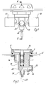
- the assembly consisting of the air regulating device and the pneumatic switch for the circulation pump has a housing 1 which is equipped with a fastening flange 2 which is supported on the edge of an opening in the tub 3.
- the mounting flange is ring-shaped and has a circumferential, outwardly open groove in which an elastic ring 4 is fixed.
- This elastic ring engages in an annular groove of a regulating disk 5, which is held on the fastening flange 2 by the elastic ring 4, but is rotatably mounted.
- the regulating disc 5 is equipped with a kidney-shaped air passage 6, which can be brought into the area of one or two inflow openings of the air channels 7 and 8 provided in the housing, which are also kidney-shaped in cross section.
- the housing part adjoining the fastening flange 2 is provided with an external thread 9, onto which a nut 10 is screwed, by means of which the housing is fixed at the edge of the opening in the tub 3.
- a connector 11 is pushed onto the rear part of the housing, which is adapted to the contour of the rear housing part and is positively attached to the housing part.
- the connector 11 is additionally firmly connected to the rear housing part by means of an adhesive.
- connection sleeves 12 in which the ends of the air lines leading to the mixing housing of the inlet nozzles are fixed. From Fig. 4 it follows that the air channels 7 and 8 open into the connecting sleeves 12.
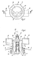
- a cylinder chamber 13 In the central area of the housing, a cylinder chamber 13 is provided, in which a piston 14 is slidably mounted against the action of a spring 15.
- This piston is actuated by means of a disk 16, which is arranged in a cylindrical, outwardly open recess 17 of the regulating disk 5.
- An annular air gap is provided between the edge of the disc 16 and the annular surface 18 of the recess, so that the disc 16 is surrounded by air in all operating positions. If the air passage of the regulating disk 5 is in the region of the inflow openings of the air channels 7 and 8, air can flow into the channels 7 and 8 in every operating position of the disk 16.
- a channel 20 leads from the cylindrical chamber 13 to the outer end of a connecting piece 21 which is provided with an external thread and to which, in the exemplary embodiment according to FIG. 4, a connecting sleeve 22 is screwed for a line 23 leading to the actuation switch of the circulating pump.
- the housing is provided with a further nozzle 24 which extends at a right angle to the nozzle 21 and is equipped with a channel 25 which opens into the channel 20.
- the connector 24, which is also provided with an external thread, is closed in the exemplary embodiment according to FIG. 2 by a closure cap 26.
- the closure cap 26 and the connecting sleeve 22 can be exchanged, depending on which connection piece the line 23 leading to the actuation switch of the circulating pump is to be connected to.
Landscapes
- Health & Medical Sciences (AREA)
- Public Health (AREA)
- Epidemiology (AREA)
- Pain & Pain Management (AREA)
- Physical Education & Sports Medicine (AREA)
- Rehabilitation Therapy (AREA)
- Life Sciences & Earth Sciences (AREA)
- Animal Behavior & Ethology (AREA)
- General Health & Medical Sciences (AREA)
- Veterinary Medicine (AREA)
- Percussion Or Vibration Massage (AREA)
- Jet Pumps And Other Pumps (AREA)
- Compressors, Vaccum Pumps And Other Relevant Systems (AREA)
- Massaging Devices (AREA)
Abstract
Description
- Die Erfindung bezieht sich auf eine Luftreguliervorrichtung für die mit einem Injektor ausgestatteten Einlaßdüsen einer Whiripool-Wanne, mit einer mit einem Luftdurchlaß ausgerüsteten, drehbar an einem an der Wanne festlegbaren Gehäuse gelagerten Regulierscheibe, wobei der Wanne eine Wasser aus der Wanne absaugende und zu den Injektoren fördernde Umwälzpumpe zugeordnet ist, die mittels eines einen handbetätigten Kolben aufweisenden Pneumatikschalters betätigbar ist.
- Das Ein- und Ausschalten der Umwälzpumpe einer Whirlpool-Wanne erfolgt aus sicherheitstechnischen Gründen mittels eines Pneumatikschalters. Durch Betätigen eines in einer Zylinderkammer gleitbar gelagerten Kolbens wird die in der Zylinderkammer des Schalters vorhandene Luft komprimiert. Der dadurch entstehende Luftimpuls wird durch eine Schlauchleitung weitergeführt und betätigt den Schalter der Umwälzpumpe.
- Zur Luftmengenregulierung der an den Wannenseiten eingebrachten Einlaßdüsen, durch die ein Wasser-Luft-Gemisch in die Wanne eingeführt wird, wird an jeder Wannenseite eine Reguliervorrichtung benötigt, um den Einlaßdüsen die erforderliche Luft zuzuführen, damit die Strahlintensität der Einlaßdüsen unabhängig voneinader gesteuert werden kann.
- Bei den bekannten Reguliervorrichtungen wird die Luftmenge durch Auf-und Zudrehen einer Regulierkappe geregelt und dem Mischgehäuse der Einlaßdüse zugeführt. Im Mischgehäuse wird nach dem Injektorprinzip durch den aus dem Injektor austretenden Wasserstrahl die zugeführte Luft angesaugt und je nach Stellung der Regulierkappen eine unterschiedliche Strahlintensität der Einlaßdüsen erreicht.
- Die Anordnung der beschriebenen Betätigungs- und Reguliervorrichtungen erfordert mehrere Durchbrüche am oberen'Wannenrand und ist konstruktiv durch die Vielzahl der Einzelteile sehr aufwendig.
- Da die Installation der genannten Vorrichtungen nicht in jedem Fall am Wannenrand erfolgen kann, muß ggf. die Installation in dem der Wanne benachbart liegenden Mauerwerk erfolgen. Da zum Teil die flexiblen Anschlußleitungen tief in das Mauerwerk verlegt werden müssen, besteht die Gefahr des Abknickens dieser Anschlußleitungen.
- Der Erfindung liegt die Aufgabe zugrunde, die Luftreguliervorrichtung und den Pneumatikschalter für die Umwälzpumpe so anzuordnen und auszubilden, daß sie zu einer Baueinheit zusammengefaßt werden können, die in einem Durchbruch des Wannenrandes festgelegt wird.
- Diese Aufgabe wird nach der Erfindung bei einer Luftreguliervorrichtung der eingangs genannten Art dadurch gelöst, daß der Kolben des Pneumatikschalters in einer Kammer des Gehäuses der Luftreguliervorrichtung gleitbar gelagert und mittels einer luftumströmten Scheibe betätigbar ist, die in allen Betriebslagen mit Abstand den Luftdurchlaß der Regulierscheibe abdeckt. Beim Gegenstand der Erfindung weisen die Luftreguliervorrichtung und der Pneumatikschalter zur Betätigung der Umwälzpumpe ein gemeinsamens Gehäuse auf, so daß eine einfache Montage dieser Baueinheit gegeben ist.
- Bei einer vorteilhaften Ausführungsform dieser Baueinheit ist das Gehäuse miteinem in der Längsachse liegenden und einem im rechten Winkel dazu sich erstreckenden Stutzen ausgerüstet. Diese Stutzen weisen Kanäle auf, die mit dem Kompressionsbereich des Pneumatikschalters verbunden sind. Die Stutzen sind mit einem Außengewinde versehen, auf das eine Verschlußkappe oder eine Anschlußtülle geschraubt werden kann. Nach den örtlichen Gegebenheiten kann von dem Monteur entschieden werden, ob er den einen oder den anderen Anschlußstutzen verwenden will, um den Schlauch anzuschließen, durch den der im Pneumatikschalter erzeugte Luftimpuls zu dem Schalter der Umwälzpumpe geleitet wird.
- Weitere Merkmale der Erfindung ergeben sich aus den Unteransprüchen und der folgenden Beschreibung einer vorteilhaften beispielsweisen in den Zeichnungen dargestellten Ausführungsform.
- Es zeigen:
- Fig. 1 die aus der Luftreguliervorrichtung und dem Pneumatikschalter der Umwälzpumpe bestehende Baueinheit im Grundriß,
- Fig. 2 einen Schnitt nach der Linie II in Fig. 1,
- Fig. 3 die Baueinheit im Aufriß und
- Fig. 4 einen Schnitt nach der Linie IV-IV in Fig. 3.
- Die aus der Luftreguliervorrichtung und dem Pneumatikschalter für die Umwälzpumpe bestehende Baueinheit weist ein Gehäuse 1 auf, das mit einem Befestigungsflansch 2 ausgerüstet ist, der sich an dem Rand eines Durchbruchs in der Wanne 3 abstützt. Der Befestigungsflansch ist ringförmig ausgebildet und weist eine umlaufende nach außen geöffnete Nut auf, in der ein elastischer Ring 4 festgelegt ist. Dieser elastische Ring greift in eine Ringnut einer Regulierscheibe 5, die durch den elastischen Ring 4 an dem Befestigungsflansch 2 gehalten wird, jedoch drehbar gelagert ist. Die Regulierscheibe 5 ist mit einem nierenförmigen Luftdurchlaß 6 ausgerüstet, der in den Bereich eines oder zweier Einströmöffnungen der im Gehäuse vorgesehenen Luftkanäle 7 und 8 gebracht werden kann, die im Querschnitt ebenfalls nierenförmig sind. Der sich an den Befestigungsflansch 2 anschließende Gehäuseteil ist mit einem Außengewinde 9 versehen, auf das eine Mutter 10 geschraubt ist, durch die das Gehäuse am Rand des Durchbruches der Wanne 3 festgelegt wird. Auf den hinteren Teil des Gehäuses wird in dem dargestellten Ausführungsbeispiel ein Anschlußstück 11 geschoben, das der Kontur des hinteren Gehäuseteils angepaßt ist und formschlüssig an dem Gehäuseteil festgelegt wird. Das Anschlußstück 11 wird zusätzlich über einen Kleber mit dem hinteren Gehäuseteil fest verbunden.
- Das Anschlußstück weist Anschlußmuffen 12 auf, in denen die Enden der zum Mischgehäuse der Einlaßdüsen führenden Luftleitungen festgelegt werden. Aus der Fig. 4 ergibt sich, daß die Luftkanäle 7 und 8 in die Anschlußmuffen 12 einmünden.
- Im mittleren Bereich des Gehäuses ist eine Zylinderkammer 13 vorgesehen, in der ein Kolben 14 entgegen der Wirkung einer Feder 15 gleitbar gelagert ist. Dieser Kolben wird mittels einer Scheibe 16 betätigt, die in einer zylindrischen, nach außen geöffneten Ausnehmung 17 der Regulierscheibe 5 angeordnet ist. Zwischen dem Rand der Scheibe 16 und der Ringfläche 18 der Ausnehmung ist ein ringförmiger Luftspalt vorgesehen, so daß die Scheibe 16 in allen Betriebslagen luftumströmt ist. Sofern der Luftdurchlaß der Regulierscheibe 5 im Bereich der Einströmöffnungen der Luftkanäle 7 und 8 liegt, kann in jeder Betriebslage der Scheibe 16 Luft in die Kanäle 7 und 8 einströmen.
- Um die Betätigung der Regulierscheibe 5 zu vereinfachen, ist diese mit Griffmulden 19 ausgerüstet.
- Von der zylindrischen Kammer 13 führt ein Kanal 20 bis zum äußeren Ende eines Stutzens 21, der mit einem Außengewinde versehen ist und auf den in dem Ausführungsbeispiel nach der Fig. 4 eine Anschlußtülle 22 für eine zum Betätigungsschalter der Umwälzpumpe führende Leitung 23 geschraubt ist. Aus der Fig. 2 ergibt sich, daß das Gehäuse mit einem weiteren Stutzen 24 versehen ist, der in einem rechten Winkel zu dem Stutzen 21 sich erstreckt und mit einem Kanal 25 ausgerüstet ist, der in den Kanal 20 einmündet. Der Stutzen 24 der ebenfalls mit einem Außengewinde versehen ist, wird in dem Ausführungsbeispiel nach der Fig. 2 durch eine Verschlußkappe 26 verschlossen. Die Verschlußkappe 26 und die Anschlußtülle 22 können ausgetauscht werden, je nachdem an welchen Stutzen die zum Betätigungsschalter der Umwälzpumpe führende Leitung 23 angeschlossen werden soll.
-
- 1 Gehäuse
- 2 Befestigungsflansch
- 3 Wanne
- 4 Ring
- 5 Regulierscheibe
- 6 Luftdurchlaß
- 7 Luftkanal
- 8 Luftkanal
- 9 Außengewinde
- 10 Mutter
- 11 Anschlußstück
- 12 Anschlußmuffe
- 13 Zylinderkammer
- 14 Kolben
- 15 Feder
- 16 Scheibe
- 17 Ausnehmung
- 18 Ringfläche
- 19 Griffmulde
- 20 Kanal
- 21 Stutzen
- 22 Anschlußtülle
- 23 Leitung
- 24 Stutzen
- 25 Kanal
Claims (7)
Applications Claiming Priority (2)
| Application Number | Priority Date | Filing Date | Title |
|---|---|---|---|
| DE19833309760 DE3309760A1 (de) | 1983-03-18 | 1983-03-18 | Luftreguliervorrichtung fuer die einlassduesen einer whirlpool-wanne |
| DE3309760 | 1983-03-18 |
Publications (3)
| Publication Number | Publication Date |
|---|---|
| EP0119582A2 true EP0119582A2 (de) | 1984-09-26 |
| EP0119582A3 EP0119582A3 (en) | 1985-01-09 |
| EP0119582B1 EP0119582B1 (de) | 1986-06-18 |
Family
ID=6193871
Family Applications (1)
| Application Number | Title | Priority Date | Filing Date |
|---|---|---|---|
| EP84102717A Expired EP0119582B1 (de) | 1983-03-18 | 1984-03-13 | Luftreguliervorrichtung für die Einlassdüsen einer Whirlpool-Wanne |
Country Status (3)
| Country | Link |
|---|---|
| US (1) | US4577353A (de) |
| EP (1) | EP0119582B1 (de) |
| DE (1) | DE3309760A1 (de) |
Families Citing this family (12)
| Publication number | Priority date | Publication date | Assignee | Title |
|---|---|---|---|---|
| US4637080A (en) * | 1985-12-19 | 1987-01-20 | Hutchinson Charles H | Air volume control |
| DE3745124C2 (de) * | 1986-09-10 | 1999-09-02 | Schuessler | Hydromassagedüse |
| US4785484A (en) * | 1986-11-18 | 1988-11-22 | Alopex Industries, Inc. | Control valve |
| US4823413A (en) * | 1988-03-14 | 1989-04-25 | Hydrabaths, Inc. | Combined pneumatic switch and air control for use in whirpool baths |
| AU111502S (en) | 1989-07-24 | 1991-07-11 | Opaltech Pty Ltd | A valve member |
| US5118909A (en) * | 1990-10-31 | 1992-06-02 | Kohler Co. | Switch actuator |
| US5381563A (en) * | 1992-12-24 | 1995-01-17 | Roger Carrier | Check valve, and hydromassaging apparatus comprising at least one of such a check valve |
| US6071042A (en) * | 1998-04-07 | 2000-06-06 | Tichelar; Craig | Artificial wave surge apparatus and method |
| US6357233B1 (en) | 1999-04-20 | 2002-03-19 | Kipley Roydon Marks | Air switch operator |
| AU776282B2 (en) * | 1999-05-12 | 2004-09-02 | Kipley Roydon Marks | Air switch operator |
| WO2008006212A1 (en) * | 2006-07-12 | 2008-01-17 | C.G. Air Systèmes Inc. | Interface system for tubs |
| US20110154814A1 (en) * | 2009-12-31 | 2011-06-30 | Campbell Graham J | Pneumatic actuator and electrical switch system |
Family Cites Families (9)
| Publication number | Priority date | Publication date | Assignee | Title |
|---|---|---|---|---|
| US3522998A (en) * | 1968-02-26 | 1970-08-04 | Deere & Co | Constant pressure radial piston pump |
| US3977027A (en) * | 1972-02-25 | 1976-08-31 | Willy Speck | Water current-producing apparatus |
| DE2249338C3 (de) * | 1972-10-07 | 1980-01-31 | Martin 4030 Ratingen Schydlo | Einbauarmatur |
| US3986217A (en) * | 1972-12-07 | 1976-10-19 | Doerr John J | Whirlpool bath device |
| US4169293A (en) * | 1978-02-08 | 1979-10-02 | Chanso Corporation | Hydrotherapy vessel level control |
| US4248570A (en) * | 1978-04-17 | 1981-02-03 | Conger William W Iv | Air blower for spas or the like |
| DE2832804C3 (de) * | 1978-07-26 | 1981-12-10 | Martin van Nijmegen Gemert | Steuervorrichtung für die Wasserversorgung einer Badewanne |
| DE2846263C2 (de) * | 1978-10-12 | 1984-10-04 | Walter 7483 Inzigkofen Frenkel | Sicherheitsventil mit auswechselbarem Schmutzfilter |
| US4419775A (en) * | 1981-08-10 | 1983-12-13 | Ebert Thomas P | Whirlpool bath |
-
1983
- 1983-03-18 DE DE19833309760 patent/DE3309760A1/de active Granted
-
1984
- 1984-03-13 US US06/589,190 patent/US4577353A/en not_active Expired - Fee Related
- 1984-03-13 EP EP84102717A patent/EP0119582B1/de not_active Expired
Also Published As
| Publication number | Publication date |
|---|---|
| DE3309760A1 (de) | 1984-09-20 |
| EP0119582A3 (en) | 1985-01-09 |
| EP0119582B1 (de) | 1986-06-18 |
| US4577353A (en) | 1986-03-25 |
| DE3309760C2 (de) | 1992-04-16 |
Similar Documents
| Publication | Publication Date | Title |
|---|---|---|
| DE68911842T2 (de) | Filtersystem. | |
| EP0119582B1 (de) | Luftreguliervorrichtung für die Einlassdüsen einer Whirlpool-Wanne | |
| DE69918403T2 (de) | Sprühkopf für Medien wie Farbe | |
| DE3538744A1 (de) | Reinigungsvorrichtung fuer die durchgangskanaele eines endoskopes | |
| DE2360539A1 (de) | Filtervorrichtung | |
| DE4306632A1 (en) | Adaptor for connecting fan to breathing protection mask - incorporates short air inlet duct to reduce air flow resistance | |
| DE3619852A1 (de) | Filter | |
| DE3316113C2 (de) | Spritzpistole | |
| DE3022443A1 (de) | Brennkraftmaschine mit einem saugrohr fuer den schmieroelkreislauf | |
| DE8307972U1 (de) | Luftreguliervorrichtung fuer die einlassduesen einer whirlpool-wanne | |
| DE3720637C1 (en) | Nozzle for installation in a borehole in a bath tub | |
| DE2922094A1 (de) | Handbrause | |
| DE688712C (de) | Spritzgeraet fuer Anstrichmassen | |
| EP1090666A1 (de) | Flüssigkeitsfilter mit Schlauchstutzen als Anschluss | |
| DE3428288C2 (de) | ||
| EP0014993A1 (de) | Spritzpistole mit Treibgasantrieb | |
| EP0937490B1 (de) | Filtereinrichtung in Modulbauweise | |
| DE2852981A1 (de) | Wasserverteiler fuer ein zylindrisches filtersieb | |
| EP1908961B1 (de) | Teichpumpe mit zwei Ansaugkanälen | |
| DE3779620T2 (de) | Wasser- und/oder luft-einspritzduese fuer eine badewanne einer balneotherapie-einrichtung. | |
| DE3044880C2 (de) | Rückflußverhinderungsventil | |
| DE3921937A1 (de) | Vorrichtung zur befestigung von wasserbelueftern an druckluftsammelleitungen | |
| DE102014102548A1 (de) | Vorrichtung zum Einsatz in einem Tabletten-Coater | |
| DE20118332U1 (de) | Düse für Whirlpoolwannen | |
| DE20007980U1 (de) | Verbindungseinrichtung |
Legal Events
| Date | Code | Title | Description |
|---|---|---|---|
| PUAI | Public reference made under article 153(3) epc to a published international application that has entered the european phase |
Free format text: ORIGINAL CODE: 0009012 |
|
| AK | Designated contracting states |
Designated state(s): BE FR GB NL |
|
| PUAL | Search report despatched |
Free format text: ORIGINAL CODE: 0009013 |
|
| AK | Designated contracting states |
Designated state(s): BE FR GB NL |
|
| 17P | Request for examination filed |
Effective date: 19841123 |
|
| GRAA | (expected) grant |
Free format text: ORIGINAL CODE: 0009210 |
|
| AK | Designated contracting states |
Kind code of ref document: B1 Designated state(s): BE FR GB NL |
|
| ET | Fr: translation filed | ||
| PLBE | No opposition filed within time limit |
Free format text: ORIGINAL CODE: 0009261 |
|
| STAA | Information on the status of an ep patent application or granted ep patent |
Free format text: STATUS: NO OPPOSITION FILED WITHIN TIME LIMIT |
|
| 26N | No opposition filed | ||
| PGFP | Annual fee paid to national office [announced via postgrant information from national office to epo] |
Ref country code: FR Payment date: 19930311 Year of fee payment: 10 |
|
| PGFP | Annual fee paid to national office [announced via postgrant information from national office to epo] |
Ref country code: GB Payment date: 19930312 Year of fee payment: 10 |
|
| PGFP | Annual fee paid to national office [announced via postgrant information from national office to epo] |
Ref country code: BE Payment date: 19930318 Year of fee payment: 10 |
|
| PGFP | Annual fee paid to national office [announced via postgrant information from national office to epo] |
Ref country code: NL Payment date: 19930331 Year of fee payment: 10 |
|
| PG25 | Lapsed in a contracting state [announced via postgrant information from national office to epo] |
Ref country code: GB Effective date: 19940313 |
|
| PG25 | Lapsed in a contracting state [announced via postgrant information from national office to epo] |
Ref country code: BE Effective date: 19940331 |
|
| BERE | Be: lapsed |
Owner name: FIRMA FRANZ VIEGENER II Effective date: 19940331 |
|
| PG25 | Lapsed in a contracting state [announced via postgrant information from national office to epo] |
Ref country code: NL Effective date: 19941001 |
|
| GBPC | Gb: european patent ceased through non-payment of renewal fee |
Effective date: 19940313 |
|
| NLV4 | Nl: lapsed or anulled due to non-payment of the annual fee | ||
| PG25 | Lapsed in a contracting state [announced via postgrant information from national office to epo] |
Ref country code: FR Effective date: 19941130 |
|
| REG | Reference to a national code |
Ref country code: FR Ref legal event code: ST |