EP0119642A1 - Dispositif pour mélanger un gaz au courant principal d'un deuxième gaz - Google Patents
Dispositif pour mélanger un gaz au courant principal d'un deuxième gaz Download PDFInfo
- Publication number
- EP0119642A1 EP0119642A1 EP84200175A EP84200175A EP0119642A1 EP 0119642 A1 EP0119642 A1 EP 0119642A1 EP 84200175 A EP84200175 A EP 84200175A EP 84200175 A EP84200175 A EP 84200175A EP 0119642 A1 EP0119642 A1 EP 0119642A1
- Authority
- EP
- European Patent Office
- Prior art keywords
- gas
- openings
- mixing
- main
- opening
- Prior art date
- Legal status (The legal status is an assumption and is not a legal conclusion. Google has not performed a legal analysis and makes no representation as to the accuracy of the status listed.)
- Granted
Links
- 238000002156 mixing Methods 0.000 title claims abstract description 37
- 230000033001 locomotion Effects 0.000 claims abstract description 10
- 239000008188 pellet Substances 0.000 abstract description 6
- 238000001035 drying Methods 0.000 abstract description 3
- 239000007789 gas Substances 0.000 description 61
- 238000009434 installation Methods 0.000 description 4
- 238000005453 pelletization Methods 0.000 description 4
- XLYOFNOQVPJJNP-UHFFFAOYSA-N water Substances O XLYOFNOQVPJJNP-UHFFFAOYSA-N 0.000 description 4
- 238000010304 firing Methods 0.000 description 3
- XEEYBQQBJWHFJM-UHFFFAOYSA-N Iron Chemical compound [Fe] XEEYBQQBJWHFJM-UHFFFAOYSA-N 0.000 description 2
- NINIDFKCEFEMDL-UHFFFAOYSA-N Sulfur Chemical compound [S] NINIDFKCEFEMDL-UHFFFAOYSA-N 0.000 description 2
- 239000005864 Sulphur Substances 0.000 description 2
- OSGAYBCDTDRGGQ-UHFFFAOYSA-L calcium sulfate Chemical compound [Ca+2].[O-]S([O-])(=O)=O OSGAYBCDTDRGGQ-UHFFFAOYSA-L 0.000 description 2
- 238000010276 construction Methods 0.000 description 2
- 230000005611 electricity Effects 0.000 description 2
- 238000000034 method Methods 0.000 description 2
- 229920006395 saturated elastomer Polymers 0.000 description 2
- 238000000926 separation method Methods 0.000 description 2
- 238000005406 washing Methods 0.000 description 2
- 235000008733 Citrus aurantifolia Nutrition 0.000 description 1
- 206010053615 Thermal burn Diseases 0.000 description 1
- 235000011941 Tilia x europaea Nutrition 0.000 description 1
- 239000000440 bentonite Substances 0.000 description 1
- 229910000278 bentonite Inorganic materials 0.000 description 1
- SVPXDRXYRYOSEX-UHFFFAOYSA-N bentoquatam Chemical compound O.O=[Si]=O.O=[Al]O[Al]=O SVPXDRXYRYOSEX-UHFFFAOYSA-N 0.000 description 1
- 239000011230 binding agent Substances 0.000 description 1
- 238000007664 blowing Methods 0.000 description 1
- 239000001175 calcium sulphate Substances 0.000 description 1
- 235000011132 calcium sulphate Nutrition 0.000 description 1
- 239000004927 clay Substances 0.000 description 1
- 238000002485 combustion reaction Methods 0.000 description 1
- 238000009833 condensation Methods 0.000 description 1
- 230000005494 condensation Effects 0.000 description 1
- 238000001816 cooling Methods 0.000 description 1
- 230000008878 coupling Effects 0.000 description 1
- 238000010168 coupling process Methods 0.000 description 1
- 238000005859 coupling reaction Methods 0.000 description 1
- 238000004134 energy conservation Methods 0.000 description 1
- 239000000446 fuel Substances 0.000 description 1
- 239000010440 gypsum Substances 0.000 description 1
- 229910052602 gypsum Inorganic materials 0.000 description 1
- 238000010438 heat treatment Methods 0.000 description 1
- 229910052742 iron Inorganic materials 0.000 description 1
- 239000004571 lime Substances 0.000 description 1
- 238000005259 measurement Methods 0.000 description 1
- 239000000203 mixture Substances 0.000 description 1
- XTQHKBHJIVJGKJ-UHFFFAOYSA-N sulfur monoxide Chemical class S=O XTQHKBHJIVJGKJ-UHFFFAOYSA-N 0.000 description 1
Images

Classifications
-
- F—MECHANICAL ENGINEERING; LIGHTING; HEATING; WEAPONS; BLASTING
- F23—COMBUSTION APPARATUS; COMBUSTION PROCESSES
- F23J—REMOVAL OR TREATMENT OF COMBUSTION PRODUCTS OR COMBUSTION RESIDUES; FLUES
- F23J15/00—Arrangements of devices for treating smoke or fumes
- F23J15/08—Arrangements of devices for treating smoke or fumes of heaters
-
- B—PERFORMING OPERATIONS; TRANSPORTING
- B01—PHYSICAL OR CHEMICAL PROCESSES OR APPARATUS IN GENERAL
- B01F—MIXING, e.g. DISSOLVING, EMULSIFYING OR DISPERSING
- B01F23/00—Mixing according to the phases to be mixed, e.g. dispersing or emulsifying
- B01F23/10—Mixing gases with gases
-
- B—PERFORMING OPERATIONS; TRANSPORTING
- B01—PHYSICAL OR CHEMICAL PROCESSES OR APPARATUS IN GENERAL
- B01F—MIXING, e.g. DISSOLVING, EMULSIFYING OR DISPERSING
- B01F25/00—Flow mixers; Mixers for falling materials, e.g. solid particles
- B01F25/20—Jet mixers, i.e. mixers using high-speed fluid streams
-
- Y—GENERAL TAGGING OF NEW TECHNOLOGICAL DEVELOPMENTS; GENERAL TAGGING OF CROSS-SECTIONAL TECHNOLOGIES SPANNING OVER SEVERAL SECTIONS OF THE IPC; TECHNICAL SUBJECTS COVERED BY FORMER USPC CROSS-REFERENCE ART COLLECTIONS [XRACs] AND DIGESTS
- Y10—TECHNICAL SUBJECTS COVERED BY FORMER USPC
- Y10T—TECHNICAL SUBJECTS COVERED BY FORMER US CLASSIFICATION
- Y10T137/00—Fluid handling
- Y10T137/8593—Systems
- Y10T137/87571—Multiple inlet with single outlet
- Y10T137/87652—With means to promote mixing or combining of plural fluids
Definitions
- This invention relates to a conduit arrangement for mixing a first gas into a main flow of a second gas, and to a conduit system including such an arrangement.
- the mixing arrangement has a main conduit for said main flow and a plurality of supply conduits for the first gas which debouch into said main conduit.
- Fig. 1. a mixing arrangement of the above-described type in which the number of supply conduits for the gas being admixed is two. These conduits protrude radially through the wall of the cylindrically shaped main conduit and lie in a plane at right angles to the axis of the main conduit. In the main conduit, they are bent through an angle of about 30° in the same sense, and each has a round opening at its extremity, with the mutually parallel centre lines of these openings having a separation less than half the internal diameter of the main conduit.
- the gas being admixed is directed from the openings in mutually parallel but opposite directions with respect to the main conduit axis and circulates in a vortex around the axis in a single direction.
- US-A-4150817 discloses a different mixing system in which similarly a single vortex is created by two supply conduits which open at the wall of the main conduit.
- FR-A-2206971 shows a mixing arrangement in which twelve supply conduits open at circumferentially spaced points around the main conduit.
- the object of the present invention is to provide a gas mixing arrangement in which complete mixing of the gases is achieved in a very short distance from the region of introduction of the admixed gas into the main flow.
- a short mixing distance is important in large industrial installations where each saving in investment and in space is important. It may also be desirable in some circumstances to obtain the mixing of both gases as rapidly as possible in order for example to smooth out concentration or temperature differences.
- the gas mixing arrangement has supply conduits which provide at least one set of three outlet openings of which a first one, which has a larger flow rate than the other two (preferably half the total flow rate of admixed gas), opens generally perpendicularly to the main conduit wall while the other two openings of the set are offset or non-radial with respect to the first one so that the three openings cooperate to direct the admitted gas into two mutually contra-rotating circulatory movements or vortices within the main conduit, as seen looking axially along the main conduit.
- a plurality of such sets of three openings may provide more than two such contra-rotating circulatory movements.
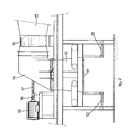
- Figs. 1 and 2 illustrate a system embodying the present invention for the admixture of hot air at 300°-400°C into a relatively cold (about 50°C) airstream emerging from the drying zone which airstream is laden with SO 2 and is drawn off through a hood 10 located above the pellet conveyor 11 (Fig. 2). Access platforms 12,13 are shown on opposite sides of the pellet conveyor 11.
- the hood 10 tapers upwardly, has a rectangular cross-section and is connected via a right-angle bend 14 to a cylindrical horizontal duct 15, in which an axial fan is located at the position 16. This fan is driven by an electric motor 19 via a shaft 17 and a flexible coupling 18.
- Hot air at 300°-400°C from another part of the pelletizing plant is supplied via a duct 20 to be admixed into the main flow of cool air passing through the hood 10.
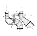
- the air flow from the duct 20 is admitted into the hood 10 by a distribution system comprising three ducts 21,23,24, respectively connected through the walls of the hood by mouthpieces 22,25,26.
- the first distributin duct 21,22 carries about half the air flow in the duct 20 and directs the air perpendicularly through one side wall of the hood substantially at a longitudinal mid-plane of the hood (i.e. a plane perpendicular to the paper in Fig. 1).
- the other two distribution ducts 23,25 and 24,26 each carry about one-quarter of the flow in the duct 20, and each extend around the hood to open perpendicularly through the opposite side wall of the hood at points symmetrically offset with respect to the said mid-plane of the hood.
- the axes of the three openings 22,25,26 lie in the same transverse plane (parallel to the paper in Fig. 1).
- the flow into the hood from the first distribution duct 21,22 can thus be said to be radial while the flows from the other two distribution ducts are non-radial and opposed to but offset from the first flow so that two circulatory movement of the air being admitted, opposite in rotational sense, are set up in the hood (as seen in the direction of Fig. 1).
- This method of mixing ensures that the gases are quickly and well mixed before they reach the fan 16, so that the fan corrodes less quickly and can operate for longer.
- the mixing distance can thus be very short, and within a short distance in the flow direction a rapid and efficient intermixing of two gases of different temperature is possible without requiring a voluminous and expensive construction and without a high expenditure of energy.
- the measured pressure loss is small, i.e. 0.35 times the velocity pressure loss in the main duct, which is very small.
- the exhaust gases produced by a large electricity generating unit must, in accordance with present day requirements, be adequately desulphurized before being released into the atmosphere, and this desulphurization can be carried out by washing the gases in a so-called washing tower.
- the hot exhaust gases are there brought into contact with a counter-current of droplets of lime- containing water.
- the water carries away the sulphur oxides., and the. calcium sulphate or gypsum which is thus produced can be utilised elsewhere.
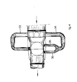
- the branch duct 32 divides into two ducts 33 and 34, each carrying half the flow of the duct 32.
- the duct 33 opens perpendicularly through the wall of the duct 31 at a central axial plane thereof while the duct 34 is again divided into two ducts 35,36 carrying approximately equal flows which open, parallel and opposed to the duct 34, through the opposite side of the duct 31 at the same transverse plane.
- the openings of the two smaller ducts 35,36 are non-radial and offset relative to that of the duct 33, so that two mutually contra-rotating circulatory movements (vortices) of the gas being admitted are set up in the duct 31.
- the quantity of hot exhaust gas tapped off by the duct 32 is thus quickly and effectively mixed into the main flow of treated exhaust gas in the duct 31 and raises its temperature by about 5 0 so that further transport of the treated gas through the duct 31 to a chimney at above the dew point is ensured.
- This addition of about 10% of hot sulphur bearing exhaust gas must be taken into account, in assessing the permissible release of the gas flow.
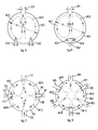
- Fig. 5 The principle on which the present invention is based is shown schematically in Fig. 5. This shows the wall 50 of a cylindrical main duct through which is carried a gas to which another gas is being added. This mixing may have to satisfy a number of requirements, such as the following:-
- the first supply conduit 51 is mounted radially with respect to the wall 50 and its outlet opening has a passage dimension such that about half the total quantity of the admixed gas enters through it.
- the two other supply conduits 52 and 53 are mounted parallel and opposed to the conduit 51 and in the same transverse plane. Their exit openings have a section area such that each transmits about a quarter of the gas being admixed.
- the conduits 52,53 are non-radial.
- Fig. 5 shows that the two smaller conduits 52 and 53 have a symmetrical arrangement with respect to the line through the centre of conduit 51.
- the desirable mutual separation of the two conduits 52 and 53 centre-to-centre is determined by the angle of the exit cone of the admixed gas in the main flow in the conduit 50, given that it is desirable to prevent any of the admixed gas from conduit 51 on the one hand and from conduits 52 and 53 ori the other from blowing back into the other conduit(s).
- the exact intention is that these flows should influence each other so that two oppositely rotating main vortices are produced, as viewed in the axial direction (Wl and W2 in Fig. 5), and these generate a very large mixing interface with the main gas stream.
- FIG. 6 The wall of the cylindrical main duct is here indicated as 60.
- the supply conduit 61 opens radially through this wall and admits about half of the total quantity of admixed gas. Diametrically opposite to it there projects inward a supply conduit 62 which has a similar flow rate.
- This conduit 62 divides a T-shape into the two short sections 63 and 64 which have outlet openings at their extremities each admitting about a quarter of the quantity of admixed gas. These openings are tangentially directed. In this way again two mutually opposite circulatory movements Wl and W2 are produced in the admixed gas within the main duct.
- Figs. 7 and 8 show further embodiments.
- Figs. 7 and 8 show further embodiments.
- By employing a larger number of groups of three outlet openings it is possible to increase the number of consecutively counter-rotating circulatory movements (vortices) of the admixed gas in the main flow and so achieve a proportionate reduction in the length along the main duct required to achieve complete mixing.
- vortices consecutively counter-rotating circulatory movements
- Fig. 7 shows four supply conduits 71,72,73,74 protruding through the wall 70 of the cylindrical main duct at circumferential intervals of 90 0 , each with a passageway dimension such that it supplies about one quarter of the quantity of the admixed gas.
- Two mutually opposed supply conduits 73 and 74 are closed at their ends and have two tangential openings 75 and 77, and 76 and 78 respectively which are of equal size and each admit about half of the quantity of admixed gas passing through the conduit ,73 or 74.
- the result is four circulatory motions or main vortices Wl,W2,W3 and W4 which contribute to achieving that the mutual mixing of the two gases is even faster.
- FIG. 8 this principle is illustrated further by an embodiment providing a total of six vortices Wl,W2,W3,W4,W5 and W6, allowing the mixing length along the axis to be shortened even further.
- This effect is achieved by mounting six radial supply conduits 81,82,83,84,85 and 86 in the main conduit wall 80 at mutual intervals of 60° each of them carrying the same flow quantity of gas being admixed into the main conduit. Alternate, these supply conduits opening radially and tangentially (parallel with the wall) in the manner already explained for Figs. 6 and 7.
- the variation coefficient (a dimensionless number) is defined as the quotient of the standard deviation and the mean, and if this is applied to the concentration of the mixture over the cross-section of the main stream in Fig. 5 at a distance downstream of the plane in which the admixed gas was injected, then it appears from measurements that a good mixing characterised by a variation coefficient of 0.04 at a distance of 2D and a somewhat better mixing with a variation coefficient of 0.02 at a distance of 4D can be obtained using this embodiment of the invention.
- the invention can be applied successfully when two gases need thorough mixing rapidly and compactly.
- the invention can be applied to cooling towers, fuel supply arrangements for burners, etc.
Landscapes
- Chemical & Material Sciences (AREA)
- Chemical Kinetics & Catalysis (AREA)
- Engineering & Computer Science (AREA)
- Mechanical Engineering (AREA)
- General Engineering & Computer Science (AREA)
- Percussion Or Vibration Massage (AREA)
- Accessories For Mixers (AREA)
- Gas Separation By Absorption (AREA)
- Treating Waste Gases (AREA)
- Drying Of Solid Materials (AREA)
- Sampling And Sample Adjustment (AREA)
Priority Applications (1)
| Application Number | Priority Date | Filing Date | Title |
|---|---|---|---|
| AT84200175T ATE23278T1 (de) | 1983-02-17 | 1984-02-07 | Vorrichtung zum mischen eines gases in einen hauptstrom eines zweiten gases. |
Applications Claiming Priority (2)
| Application Number | Priority Date | Filing Date | Title |
|---|---|---|---|
| NLAANVRAGE8300590,A NL190510C (nl) | 1983-02-17 | 1983-02-17 | Gasmenger. |
| NL8300590 | 1983-02-17 |
Publications (2)
| Publication Number | Publication Date |
|---|---|
| EP0119642A1 true EP0119642A1 (fr) | 1984-09-26 |
| EP0119642B1 EP0119642B1 (fr) | 1986-11-05 |
Family
ID=19841429
Family Applications (1)
| Application Number | Title | Priority Date | Filing Date |
|---|---|---|---|
| EP84200175A Expired EP0119642B1 (fr) | 1983-02-17 | 1984-02-07 | Dispositif pour mélanger un gaz au courant principal d'un deuxième gaz |
Country Status (12)
| Country | Link |
|---|---|
| US (1) | US4521117A (fr) |
| EP (1) | EP0119642B1 (fr) |
| JP (1) | JPS59156418A (fr) |
| AT (1) | ATE23278T1 (fr) |
| AU (1) | AU556714B2 (fr) |
| BR (1) | BR8400700A (fr) |
| CA (1) | CA1222374A (fr) |
| DE (1) | DE3461145D1 (fr) |
| ES (1) | ES529784A0 (fr) |
| MX (1) | MX158283A (fr) |
| NL (1) | NL190510C (fr) |
| ZA (1) | ZA841074B (fr) |
Cited By (3)
| Publication number | Priority date | Publication date | Assignee | Title |
|---|---|---|---|---|
| EP0185632A1 (fr) * | 1984-12-18 | 1986-06-25 | Fläkt Aktiebolag | Dispositif pour mélanger un premier milieu avec un second milieu dans un appareil pour la mise en contact de fluides à l'aide d'un ou plusieurs tourbillons |
| GB2334901A (en) * | 1998-03-04 | 1999-09-08 | Hamworthy Heating Ltd | Mixing device for diluting boiler flue gas with air |
| WO2012171851A3 (fr) * | 2011-06-16 | 2013-02-07 | Siemens Vai Metals Technologies Ltd. | Étage mélangeur |
Families Citing this family (41)
| Publication number | Priority date | Publication date | Assignee | Title |
|---|---|---|---|---|
| US4770347A (en) * | 1986-12-30 | 1988-09-13 | Sprung Philip D | Aeration assembly for a nutrient feed solution for a nutrient film propagation system for plants |
| US4899772A (en) * | 1988-10-20 | 1990-02-13 | Rockwell International Corporation | Mixing aids for supersonic flows |
| FR2665088B1 (fr) * | 1990-07-27 | 1992-10-16 | Air Liquide | Procede et dispositif de melange de deux gaz. |
| US5523063A (en) * | 1992-12-02 | 1996-06-04 | Applied Materials, Inc. | Apparatus for the turbulent mixing of gases |
| US5641462A (en) * | 1995-07-12 | 1997-06-24 | University Of Utah | Continuous solvent extraction with bottom gas injection |
| US5770167A (en) * | 1996-12-05 | 1998-06-23 | Yen; Chin-Ching | Waste gas treating apparatus |
| US6203187B1 (en) | 1998-08-06 | 2001-03-20 | Institute Of Gas Technology | Method and apparatus for controlled mixing of fluids |
| US6234664B1 (en) | 1999-02-26 | 2001-05-22 | Microtrac, Inc. | Mixing reservoir for an automated recirculating particle size analysis system |
| FR2804045B1 (fr) * | 2000-01-25 | 2002-03-29 | Air Liquide | Dispositif de melange d'un gaz secondaire dans un gaz principal |
| DE50109764D1 (de) * | 2000-05-14 | 2006-06-14 | Joerg Lehmann | Verfahren und vorrichtung zur physikalisch-chemischen behandlung fluider medien |
| US6427671B1 (en) | 2000-07-17 | 2002-08-06 | Caterpillar Inc. | Exhaust gas recirculation mixer apparatus and method |
| US6863867B2 (en) * | 2001-05-07 | 2005-03-08 | Uop Llc | Apparatus for mixing and reacting at least two fluids |
| US7115192B1 (en) * | 2001-05-07 | 2006-10-03 | Uop Llc | Apparatus and process for the synthesis of hydrogen peroxide directly from hydrogen and oxygen |
| US20060131161A1 (en) * | 2001-05-07 | 2006-06-22 | Towler Gavin P | Air sanitation with hydrogen peroxide |
| US6655829B1 (en) * | 2001-05-07 | 2003-12-02 | Uop Llc | Static mixer and process for mixing at least two fluids |
| US7097347B2 (en) * | 2001-05-07 | 2006-08-29 | Uop Llc | Static mixer and process for mixing at least two fluids |
| US6933010B2 (en) * | 2001-12-03 | 2005-08-23 | Ulvac, Inc | Mixer, and device and method for manufacturing thin-film |
| WO2004073850A1 (fr) * | 2003-02-14 | 2004-09-02 | Tokyo Electron Limited | Procede et systeme de traitement chimique |
| US7108838B2 (en) * | 2003-10-30 | 2006-09-19 | Conocophillips Company | Feed mixer for a partial oxidation reactor |
| US7416571B2 (en) * | 2005-03-09 | 2008-08-26 | Conocophillips Company | Compact mixer for the mixing of gaseous hydrocarbon and gaseous oxidants |
| TWI447329B (zh) | 2008-09-26 | 2014-08-01 | Univ Ohio State | 將碳質燃料轉化成無碳能量載體 |
| CN102597173A (zh) | 2009-09-08 | 2012-07-18 | 俄亥俄州立大学研究基金会 | 具有原位co2捕集的合成燃料和化学品生产 |
| CN105762386A (zh) | 2009-09-08 | 2016-07-13 | 俄亥俄州国家创新基金会 | 具有集成的碳捕集的重整/水裂解和用于发电的电化学系统的集成 |
| JP5290099B2 (ja) * | 2009-09-11 | 2013-09-18 | 太平洋セメント株式会社 | ガスの混合装置及びその運転方法 |
| US10010847B2 (en) | 2010-11-08 | 2018-07-03 | Ohio State Innovation Foundation | Circulating fluidized bed with moving bed downcomers and gas sealing between reactors |
| AU2012253328B2 (en) | 2011-05-11 | 2017-05-25 | Ohio State Innovation Foundation | Systems for converting fuel |
| WO2012155059A1 (fr) | 2011-05-11 | 2012-11-15 | The Ohio State University | Matériaux vecteurs d'oxygène |
| CA3148322A1 (fr) | 2013-02-05 | 2014-08-14 | Ohio State Innovation Foundation | Methodes de conversion de combustible en gaz synthetique |
| US20160030904A1 (en) * | 2013-03-13 | 2016-02-04 | Ohio State Innovation Foundation | Distributing secondary solids in packed moving bed reactors |
| WO2014152914A1 (fr) | 2013-03-14 | 2014-09-25 | Ohio State Innovation Foundation | Systèmes et procédés pour convertir des combustibles carbonés |
| TWI552203B (zh) * | 2013-12-27 | 2016-10-01 | Hitachi Int Electric Inc | A substrate processing apparatus, a manufacturing method of a semiconductor device, and a computer-readable recording medium |
| US20150238915A1 (en) | 2014-02-27 | 2015-08-27 | Ohio State Innovation Foundation | Systems and methods for partial or complete oxidation of fuels |
| CA3020406A1 (fr) | 2016-04-12 | 2017-10-19 | Ohio State Innovation Foundation | Production de gaz de synthese en boucle chimique a partir de combustibles carbones |
| US11090624B2 (en) | 2017-07-31 | 2021-08-17 | Ohio State Innovation Foundation | Reactor system with unequal reactor assembly operating pressures |
| US10549236B2 (en) | 2018-01-29 | 2020-02-04 | Ohio State Innovation Foundation | Systems, methods and materials for NOx decomposition with metal oxide materials |
| WO2020033500A1 (fr) | 2018-08-09 | 2020-02-13 | Ohio State Innovation Foundation | Systèmes, procédés et matières de conversion de sulfure d'hydrogène |
| WO2020150438A1 (fr) | 2019-01-17 | 2020-07-23 | Ohio State Innovation Foundation | Systèmes, procédés et matériaux pour la génération de gaz de synthèse en phase stable |
| US11453626B2 (en) | 2019-04-09 | 2022-09-27 | Ohio State Innovation Foundation | Alkene generation using metal sulfide particles |
| WO2021034888A1 (fr) | 2019-08-19 | 2021-02-25 | Ohio State Innovation Foundation | Nanoparticules à base d'oxyde métallique immobilisées sur un support mésoporeux |
| WO2021046156A1 (fr) | 2019-09-03 | 2021-03-11 | Ohio State Innovation Foundation | Capture de dioxyde de carbone facilitée par une réaction d'oxydo-réduction dans un gaz de combustion et conversion en monoxyde de carbone |
| WO2022006112A1 (fr) | 2020-06-29 | 2022-01-06 | Ohio State Innovation Foundation | Systèmes et procédés de haute conversion de réactif par séparation multiple de régulation de débit de réactif |
Citations (3)
| Publication number | Priority date | Publication date | Assignee | Title |
|---|---|---|---|---|
| FR2206971A1 (fr) * | 1972-11-20 | 1974-06-14 | Hoogovens Ijmuiden Bv | |
| US4150817A (en) * | 1978-02-06 | 1979-04-24 | Zimmermann & Jansen, Inc. | Mixing chamber |
| EP0060634A1 (fr) * | 1981-03-13 | 1982-09-22 | Moore, Barrett & Redwood Limited | Système d'échantillonage pour un liquide |
Family Cites Families (3)
| Publication number | Priority date | Publication date | Assignee | Title |
|---|---|---|---|---|
| US3015554A (en) * | 1957-04-18 | 1962-01-02 | Rummel Roman | Method and device for carrying out metallurgical processes, particularly air refining processes |
| NL178134C (nl) * | 1974-06-17 | 1986-02-03 | Shell Int Research | Werkwijze en inrichting voor het behandelen van een heet produktgas. |
| NL170923C (nl) * | 1979-05-11 | 1983-01-17 | Estel Hoogovens Bv | Gasmenger. |
-
1983
- 1983-02-17 NL NLAANVRAGE8300590,A patent/NL190510C/xx not_active IP Right Cessation
-
1984
- 1984-02-07 EP EP84200175A patent/EP0119642B1/fr not_active Expired
- 1984-02-07 DE DE8484200175T patent/DE3461145D1/de not_active Expired
- 1984-02-07 AT AT84200175T patent/ATE23278T1/de active
- 1984-02-10 US US06/578,846 patent/US4521117A/en not_active Expired - Lifetime
- 1984-02-14 ZA ZA841074A patent/ZA841074B/xx unknown
- 1984-02-15 CA CA000447476A patent/CA1222374A/fr not_active Expired
- 1984-02-16 ES ES529784A patent/ES529784A0/es active Granted
- 1984-02-16 AU AU24647/84A patent/AU556714B2/en not_active Ceased
- 1984-02-16 BR BR8400700A patent/BR8400700A/pt unknown
- 1984-02-17 JP JP59027376A patent/JPS59156418A/ja active Granted
- 1984-02-17 MX MX200370A patent/MX158283A/es unknown
Patent Citations (3)
| Publication number | Priority date | Publication date | Assignee | Title |
|---|---|---|---|---|
| FR2206971A1 (fr) * | 1972-11-20 | 1974-06-14 | Hoogovens Ijmuiden Bv | |
| US4150817A (en) * | 1978-02-06 | 1979-04-24 | Zimmermann & Jansen, Inc. | Mixing chamber |
| EP0060634A1 (fr) * | 1981-03-13 | 1982-09-22 | Moore, Barrett & Redwood Limited | Système d'échantillonage pour un liquide |
Cited By (3)
| Publication number | Priority date | Publication date | Assignee | Title |
|---|---|---|---|---|
| EP0185632A1 (fr) * | 1984-12-18 | 1986-06-25 | Fläkt Aktiebolag | Dispositif pour mélanger un premier milieu avec un second milieu dans un appareil pour la mise en contact de fluides à l'aide d'un ou plusieurs tourbillons |
| GB2334901A (en) * | 1998-03-04 | 1999-09-08 | Hamworthy Heating Ltd | Mixing device for diluting boiler flue gas with air |
| WO2012171851A3 (fr) * | 2011-06-16 | 2013-02-07 | Siemens Vai Metals Technologies Ltd. | Étage mélangeur |
Also Published As
| Publication number | Publication date |
|---|---|
| BR8400700A (pt) | 1984-09-25 |
| EP0119642B1 (fr) | 1986-11-05 |
| ZA841074B (en) | 1984-09-26 |
| ES8501246A1 (es) | 1984-11-16 |
| NL190510C (nl) | 1994-04-05 |
| DE3461145D1 (en) | 1986-12-11 |
| NL8300590A (nl) | 1984-09-17 |
| AU2464784A (en) | 1984-08-23 |
| CA1222374A (fr) | 1987-06-02 |
| JPS6238017B2 (fr) | 1987-08-15 |
| ES529784A0 (es) | 1984-11-16 |
| NL190510B (nl) | 1993-11-01 |
| US4521117A (en) | 1985-06-04 |
| MX158283A (es) | 1989-01-19 |
| AU556714B2 (en) | 1986-11-13 |
| ATE23278T1 (de) | 1986-11-15 |
| JPS59156418A (ja) | 1984-09-05 |
Similar Documents
| Publication | Publication Date | Title |
|---|---|---|
| US4521117A (en) | Arrangement for mixing a gas into a main flow of a second gas | |
| EP0127031B1 (fr) | Séchoir à pulvérisation | |
| US4527903A (en) | Apparatus for uniformizing the parameters of a flow and/or for mixing together at least two individual streams which discharge into a main flow | |
| KR102454646B1 (ko) | 소석고 처리 장치 및 소석고 처리 방법 | |
| EP0210966B1 (fr) | Procédé de séchage et de refroidissement de matériaux particulaires et utilisation dans un mélangeur | |
| EP4204134A1 (fr) | Système et procédé de mélange de cendres de combustion en recirculation avec de la chaux hydratée et de l'eau | |
| GB2052716A (en) | Arrangements for the mixing of air currents of different types particularly in a cooling tower | |
| US4126425A (en) | Gas mixer for sublimation purposes | |
| JPS56155617A (en) | Treatment of waste liquid in exhaust-gas treating device | |
| US2822245A (en) | Process for manufacturing sulfur dioxide by burning sulfur | |
| US5354364A (en) | High efficiency advanced dry scrubber | |
| US4392890A (en) | Cement clinker production | |
| PL173375B1 (pl) | Dysza rozpylająca do urządzenia oczyszczającego gaz | |
| EP0077434B1 (fr) | Procédé pour mélanger des courants de gaz brûlés | |
| PL107437B1 (pl) | Sposob usuwania zanieczyszczen ze strumienia gazu i urzadzenie do usuwania zanieczyszczen ze strumienia gazu | |
| CN209214384U (zh) | 一种烧结烟气外循环系统 | |
| CN115282730B (zh) | 一种用于含固湿流体的旋流喷枪及其应用 | |
| AU684186B2 (en) | Device for incorporating the purified-gas ducts from a fossil-fuel power station desulphurization plant in natural-convection wet cooling power | |
| KR200154870Y1 (ko) | 습식 석회석 석고 배연탈황설비의 석고 산화 공기 공급장치 | |
| CN216259972U (zh) | 一种钠基干法脱硫粉剂喷射装置 | |
| JPH0227313Y2 (fr) | ||
| CN216458090U (zh) | 一种用于低温烟气脱硫工艺的蒸汽掺混加热装置 | |
| CN213543081U (zh) | 一种钢铁渣烘干装置 | |
| IE43342L (en) | Air conditioning system | |
| SU1435909A1 (ru) | Устройство дл термообработки сыпучего тонкодисперсного материала |
Legal Events
| Date | Code | Title | Description |
|---|---|---|---|
| PUAI | Public reference made under article 153(3) epc to a published international application that has entered the european phase |
Free format text: ORIGINAL CODE: 0009012 |
|
| 17P | Request for examination filed |
Effective date: 19840207 |
|
| AK | Designated contracting states |
Designated state(s): AT BE CH DE FR GB IT LI LU SE |
|
| GRAA | (expected) grant |
Free format text: ORIGINAL CODE: 0009210 |
|
| AK | Designated contracting states |
Kind code of ref document: B1 Designated state(s): AT BE CH DE FR GB IT LI LU SE |
|
| REF | Corresponds to: |
Ref document number: 23278 Country of ref document: AT Date of ref document: 19861115 Kind code of ref document: T |
|
| ITF | It: translation for a ep patent filed | ||
| REF | Corresponds to: |
Ref document number: 3461145 Country of ref document: DE Date of ref document: 19861211 |
|
| ET | Fr: translation filed | ||
| PLBE | No opposition filed within time limit |
Free format text: ORIGINAL CODE: 0009261 |
|
| STAA | Information on the status of an ep patent application or granted ep patent |
Free format text: STATUS: NO OPPOSITION FILED WITHIN TIME LIMIT |
|
| 26N | No opposition filed | ||
| ITTA | It: last paid annual fee | ||
| EPTA | Lu: last paid annual fee | ||
| EAL | Se: european patent in force in sweden |
Ref document number: 84200175.2 |
|
| PGFP | Annual fee paid to national office [announced via postgrant information from national office to epo] |
Ref country code: FR Payment date: 19980112 Year of fee payment: 15 |
|
| PGFP | Annual fee paid to national office [announced via postgrant information from national office to epo] |
Ref country code: AT Payment date: 19980115 Year of fee payment: 15 |
|
| PGFP | Annual fee paid to national office [announced via postgrant information from national office to epo] |
Ref country code: SE Payment date: 19980116 Year of fee payment: 15 |
|
| PGFP | Annual fee paid to national office [announced via postgrant information from national office to epo] |
Ref country code: GB Payment date: 19980121 Year of fee payment: 15 |
|
| PGFP | Annual fee paid to national office [announced via postgrant information from national office to epo] |
Ref country code: DE Payment date: 19980126 Year of fee payment: 15 |
|
| PGFP | Annual fee paid to national office [announced via postgrant information from national office to epo] |
Ref country code: CH Payment date: 19980127 Year of fee payment: 15 |
|
| PGFP | Annual fee paid to national office [announced via postgrant information from national office to epo] |
Ref country code: LU Payment date: 19980203 Year of fee payment: 15 |
|
| PGFP | Annual fee paid to national office [announced via postgrant information from national office to epo] |
Ref country code: BE Payment date: 19980205 Year of fee payment: 15 |
|
| PG25 | Lapsed in a contracting state [announced via postgrant information from national office to epo] |
Ref country code: LU Free format text: LAPSE BECAUSE OF NON-PAYMENT OF DUE FEES Effective date: 19990207 Ref country code: GB Free format text: LAPSE BECAUSE OF NON-PAYMENT OF DUE FEES Effective date: 19990207 Ref country code: AT Free format text: LAPSE BECAUSE OF NON-PAYMENT OF DUE FEES Effective date: 19990207 |
|
| PG25 | Lapsed in a contracting state [announced via postgrant information from national office to epo] |
Ref country code: SE Free format text: LAPSE BECAUSE OF NON-PAYMENT OF DUE FEES Effective date: 19990208 |
|
| PG25 | Lapsed in a contracting state [announced via postgrant information from national office to epo] |
Ref country code: LI Free format text: LAPSE BECAUSE OF NON-PAYMENT OF DUE FEES Effective date: 19990228 Ref country code: CH Free format text: LAPSE BECAUSE OF NON-PAYMENT OF DUE FEES Effective date: 19990228 Ref country code: BE Free format text: LAPSE BECAUSE OF NON-PAYMENT OF DUE FEES Effective date: 19990228 |
|
| BERE | Be: lapsed |
Owner name: HOOGOVENS GROEP B.V. Effective date: 19990228 |
|
| GBPC | Gb: european patent ceased through non-payment of renewal fee |
Effective date: 19990207 |
|
| REG | Reference to a national code |
Ref country code: CH Ref legal event code: PL |
|
| PG25 | Lapsed in a contracting state [announced via postgrant information from national office to epo] |
Ref country code: FR Free format text: LAPSE BECAUSE OF NON-PAYMENT OF DUE FEES Effective date: 19991029 |
|
| EUG | Se: european patent has lapsed |
Ref document number: 84200175.2 |
|
| PG25 | Lapsed in a contracting state [announced via postgrant information from national office to epo] |
Ref country code: DE Free format text: LAPSE BECAUSE OF NON-PAYMENT OF DUE FEES Effective date: 19991201 |
|
| REG | Reference to a national code |
Ref country code: FR Ref legal event code: ST |