EP0119680A1 - Gerät zur Überwachung der Werkzeuglebensdauer - Google Patents
Gerät zur Überwachung der Werkzeuglebensdauer Download PDFInfo
- Publication number
- EP0119680A1 EP0119680A1 EP84300159A EP84300159A EP0119680A1 EP 0119680 A1 EP0119680 A1 EP 0119680A1 EP 84300159 A EP84300159 A EP 84300159A EP 84300159 A EP84300159 A EP 84300159A EP 0119680 A1 EP0119680 A1 EP 0119680A1
- Authority
- EP
- European Patent Office
- Prior art keywords
- signal
- reference value
- gain
- value
- tool
- Prior art date
- Legal status (The legal status is an assumption and is not a legal conclusion. Google has not performed a legal analysis and makes no representation as to the accuracy of the status listed.)
- Granted
Links
Images


Classifications
-
- G—PHYSICS
- G05—CONTROLLING; REGULATING
- G05B—CONTROL OR REGULATING SYSTEMS IN GENERAL; FUNCTIONAL ELEMENTS OF SUCH SYSTEMS; MONITORING OR TESTING ARRANGEMENTS FOR SUCH SYSTEMS OR ELEMENTS
- G05B19/00—Program-control systems
- G05B19/02—Program-control systems electric
- G05B19/18—Numerical control [NC], i.e. automatically operating machines, in particular machine tools, e.g. in a manufacturing environment, so as to execute positioning, movement or co-ordinated operations by means of program data in numerical form
- G05B19/406—Numerical control [NC], i.e. automatically operating machines, in particular machine tools, e.g. in a manufacturing environment, so as to execute positioning, movement or co-ordinated operations by means of program data in numerical form characterised by monitoring or safety
- G05B19/4065—Monitoring tool breakage, life or condition
-
- B—PERFORMING OPERATIONS; TRANSPORTING
- B23—MACHINE TOOLS; METAL-WORKING NOT OTHERWISE PROVIDED FOR
- B23Q—DETAILS, COMPONENTS, OR ACCESSORIES FOR MACHINE TOOLS, e.g. ARRANGEMENTS FOR COPYING OR CONTROLLING; MACHINE TOOLS IN GENERAL CHARACTERISED BY THE CONSTRUCTION OF PARTICULAR DETAILS OR COMPONENTS; COMBINATIONS OR ASSOCIATIONS OF METAL-WORKING MACHINES, NOT DIRECTED TO A PARTICULAR RESULT
- B23Q17/00—Arrangements for observing, indicating or measuring on machine tools
- B23Q17/09—Arrangements for observing, indicating or measuring on machine tools for indicating or measuring cutting pressure or for determining cutting-tool condition, e.g. cutting ability, load on tool
- B23Q17/0952—Arrangements for observing, indicating or measuring on machine tools for indicating or measuring cutting pressure or for determining cutting-tool condition, e.g. cutting ability, load on tool during machining
- B23Q17/0971—Arrangements for observing, indicating or measuring on machine tools for indicating or measuring cutting pressure or for determining cutting-tool condition, e.g. cutting ability, load on tool during machining by measuring mechanical vibrations of parts of the machine
-
- G—PHYSICS
- G01—MEASURING; TESTING
- G01N—INVESTIGATING OR ANALYSING MATERIALS BY DETERMINING THEIR CHEMICAL OR PHYSICAL PROPERTIES
- G01N3/00—Investigating strength properties of solid materials by application of mechanical stress
- G01N3/58—Investigating machinability by cutting tools; Investigating the cutting ability of tools
-
- G—PHYSICS
- G05—CONTROLLING; REGULATING
- G05B—CONTROL OR REGULATING SYSTEMS IN GENERAL; FUNCTIONAL ELEMENTS OF SUCH SYSTEMS; MONITORING OR TESTING ARRANGEMENTS FOR SUCH SYSTEMS OR ELEMENTS
- G05B2219/00—Program-control systems
- G05B2219/30—Nc systems
- G05B2219/37—Measurements
- G05B2219/37004—Detect absence of tool
-
- G—PHYSICS
- G05—CONTROLLING; REGULATING
- G05B—CONTROL OR REGULATING SYSTEMS IN GENERAL; FUNCTIONAL ELEMENTS OF SUCH SYSTEMS; MONITORING OR TESTING ARRANGEMENTS FOR SUCH SYSTEMS OR ELEMENTS
- G05B2219/00—Program-control systems
- G05B2219/30—Nc systems
- G05B2219/37—Measurements
- G05B2219/37242—Tool signature, compare pattern with detected signal
-
- G—PHYSICS
- G05—CONTROLLING; REGULATING
- G05B—CONTROL OR REGULATING SYSTEMS IN GENERAL; FUNCTIONAL ELEMENTS OF SUCH SYSTEMS; MONITORING OR TESTING ARRANGEMENTS FOR SUCH SYSTEMS OR ELEMENTS
- G05B2219/00—Program-control systems
- G05B2219/30—Nc systems
- G05B2219/37—Measurements
- G05B2219/37432—Detected by accelerometer, piezo electric
-
- G—PHYSICS
- G05—CONTROLLING; REGULATING
- G05B—CONTROL OR REGULATING SYSTEMS IN GENERAL; FUNCTIONAL ELEMENTS OF SUCH SYSTEMS; MONITORING OR TESTING ARRANGEMENTS FOR SUCH SYSTEMS OR ELEMENTS
- G05B2219/00—Program-control systems
- G05B2219/30—Nc systems
- G05B2219/37—Measurements
- G05B2219/37433—Detected by acoustic emission, microphone
-
- G—PHYSICS
- G05—CONTROLLING; REGULATING
- G05B—CONTROL OR REGULATING SYSTEMS IN GENERAL; FUNCTIONAL ELEMENTS OF SUCH SYSTEMS; MONITORING OR TESTING ARRANGEMENTS FOR SUCH SYSTEMS OR ELEMENTS
- G05B2219/00—Program-control systems
- G05B2219/30—Nc systems
- G05B2219/37—Measurements
- G05B2219/37434—Measuring vibration of machine or workpiece or tool
-
- G—PHYSICS
- G05—CONTROLLING; REGULATING
- G05B—CONTROL OR REGULATING SYSTEMS IN GENERAL; FUNCTIONAL ELEMENTS OF SUCH SYSTEMS; MONITORING OR TESTING ARRANGEMENTS FOR SUCH SYSTEMS OR ELEMENTS
- G05B2219/00—Program-control systems
- G05B2219/30—Nc systems
- G05B2219/37—Measurements
- G05B2219/37493—Use of different frequency band pass filters to separate different signals
-
- G—PHYSICS
- G05—CONTROLLING; REGULATING
- G05B—CONTROL OR REGULATING SYSTEMS IN GENERAL; FUNCTIONAL ELEMENTS OF SUCH SYSTEMS; MONITORING OR TESTING ARRANGEMENTS FOR SUCH SYSTEMS OR ELEMENTS
- G05B2219/00—Program-control systems
- G05B2219/30—Nc systems
- G05B2219/37—Measurements
- G05B2219/37498—Variable amplification, gain for detected signal, select correct level range
-
- G—PHYSICS
- G05—CONTROLLING; REGULATING
- G05B—CONTROL OR REGULATING SYSTEMS IN GENERAL; FUNCTIONAL ELEMENTS OF SUCH SYSTEMS; MONITORING OR TESTING ARRANGEMENTS FOR SUCH SYSTEMS OR ELEMENTS
- G05B2219/00—Program-control systems
- G05B2219/30—Nc systems
- G05B2219/37—Measurements
- G05B2219/37544—Compare detected signal to several references to derive several control actions
-
- G—PHYSICS
- G05—CONTROLLING; REGULATING
- G05B—CONTROL OR REGULATING SYSTEMS IN GENERAL; FUNCTIONAL ELEMENTS OF SUCH SYSTEMS; MONITORING OR TESTING ARRANGEMENTS FOR SUCH SYSTEMS OR ELEMENTS
- G05B2219/00—Program-control systems
- G05B2219/30—Nc systems
- G05B2219/37—Measurements
- G05B2219/37545—References to be compared vary with evolution of measured signals, auto-calibrate
-
- G—PHYSICS
- G05—CONTROLLING; REGULATING
- G05B—CONTROL OR REGULATING SYSTEMS IN GENERAL; FUNCTIONAL ELEMENTS OF SUCH SYSTEMS; MONITORING OR TESTING ARRANGEMENTS FOR SUCH SYSTEMS OR ELEMENTS
- G05B2219/00—Program-control systems
- G05B2219/30—Nc systems
- G05B2219/50—Machine tool, machine tool null till machine tool work handling
- G05B2219/50008—Multiple, multi tool head, parallel machining
Definitions
- the present invention relates to apparatus for monitoring the operating condition of cutting tools such as are used in machine tools, such as lathes, drilling machines and machining centres.
- a cutting tool such as a high speed steel twist drill which is used under a given set of operating conditions, e.g. cutting speed and feed rate, but it is of course essential to ensure that a tool is withdrawn from use before total failure becomes a distinct possibility.
- An undetected broken tool in, for example an automatic lathe can cause catastrophic damage to the workpiece, tooling and also to the machine itself.
- an automated machine might attempt to tap a'thread in a hole which is not present because a twist drill normally used to drill such holes has broken.
- a preselected frequency band of vibration of the tool is monitored through a vibration sensor and a bandpass filter and the resulting vibration signal is converted to a d.c. voltage which varies with the amplitude of the frequency of vibration.
- the d.c. voltage is compared with two different preset trip levels to (i) generate a warning signal and (ii) disengage the tool from the workpiece respectively when the levels are reached.
- This system is primarily applicable to machining situations where a number of workpieces of the same type are machined successively by a single tool of a given type at preselected machining conditions i.e. speed, feed rate, depth of cut etc., and the trip levels are chosen manually by reference to previous experimental results obtained by testing a tool of the relevant type on one particular workpiece under the same machining conditions.
- the reference vibration level with which the vibration spectrum of the tool is compared will differ for different machining conditions.
- the vibration level for soft materials is higher than that for hard materials. Therefore, using a reference vibration level obtained from a tool machining a hard material may result in a tool which is monitored while machining a softer material being discarded too early while, conversely, a tool which is monitored while machining a harder material may fail in use-before a reference vibration level is reached, and will not be detected.
- the present invention seeks to provide an improved system for monitoring the operating condition of a cutting tool.
- the present invention provides a method of monitoring the operating condition of a cutting tool during machining of a workpiece comprising the steps of
- the present invention also provides a system for monitoring the operating condition of a cutting tool during machining of a workpiece comprising monitoring means for monitoring the level of vibration of the tool on commencement of machining and generating a first signal representative of said monitored level; a variable gain circuit means for providing a second signal which is a function of said first signal; control means for automatically adjusting the gain of said gain circuit means to adjust said second signal to a preselected value;
- vibration means any mechanical wave displacement, velocity or acceleration emitted by a tool when in use and encompasses the phenomenon known as "acoustic emission”.
- machining conditions refers to controlled factors in which, in a machining operation using a cutting tool, changes could give rise to substantial alterations in the tool vibration during machining, and specifically including: cutting tool type, cutting speed, feed rate, depth of cut and workpiece material. A change in one of these factors would result in a change in machining conditions.
- the main advantage of the present invention is that a "signature" of a particular machining condition is automatically produced against which actual tool vibration can be compared to indicate the state of wear of the tool.
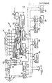
- the circuit 10 shown in Figure 1 is designed to monitor the vibration produced by tool and workpiece interaction in a machine tool such as a numerical control machine tool in a series of machining situations in which a multiplicity of different machining conditions operate sequentially.
- the different machining conditions may result from the use of different tool types in the machine, changes in tool cutting speed and the like during machining of batch workpieces.
- the circuit 10 has a vibration sensor in the form of, e.g., an accelerometer 12 which is arranged so that as the tool operates on a workpiece the predominant vibrations produced are detected by the accelerometer.
- the latter generates an electrical signal which is representative of the vibration generated at the tool- workpiece interface and this signal is transmitted through a buffer amplifier 14 to an attenuator 18, impedence-matching buffer amplifier 20, a bandpass filter 22, preferably a variable, binary switched filter, and highgain amplifier 24 to a full wave rectifier 26.
- the analogue output of the rectifier 26 is connected to a'voltage-to-frequency converter 28 which gives a digital output fed to a programmable timer 20 in turn connected to a microprocessor 32.
- the microprocessor 32 is also coupled through a parallel interface circuit 34 to control digitally the attenuator 18, filter 22 and rectifier 26.
- the microprocessor 32 is also coupled through a system bus line to the timer 30, voltage- to-frequency converter 28 and a programmable memory (ROM) 36, a programmable workspace (RAM) 38, a data entry keypad 39 and display terminal 40, and a serial interface 41 which inputs information to.the microprocessor 22 received from the machine tool controller such as a code signal identifying each machining condition.
- ROM programmable memory
- RAM programmable workspace
- serial interface 41 which inputs information to.the microprocessor 22 received from the machine tool controller such as a code signal identifying each machining condition.
- the system In normal operation, the system is manually programmed by means of the data entry terminal 40 before operation, data relating to machining conditions, such as cutting tool type to be monitored, the monitored frequency band and maximum permissible,level of vibration being entered by means of a simple programme or automatically by a computerised control system which is independent of the data entry terminal and by means of which the machine tool is controlled. Different values of the frequency band and/or the level of vibration may be selected for different machining conditions so that for example, different values may be programmed for each tool type.
- the vibration level at each cutting tool - workpiece interface at the monitored frequency relevant to that tool is compared to the permissible programmed level, the vibration level preferably being sampled over an 80ms period at about 80ms intervals.
- the system of Figure 1 has two trips which are triggered through respective driver amplifiers 42 and relays 44 and are actuated at different levels.
- the two levels may be set independently of each other but preferably one of the trips is used to warn that the tool is coming to the end of its useful life while the second trip is activiated to stop the operation of the tool or signal a tool change requirement with the ratio of the two trip levels being preselectable so that the setting of the second trip level automatically sets the first trip level.
- the first trip level is preferably adjustable as a percentage of the second trip level in the range 0-100%. At 100% the two trip leads become one.
- a further trip is also provided and is actuated through a relay driver 46 and relay 48 to stop operation of the machine tool if a certain minimum level of .tool vibration has not been reached within a programmed time interval. This ensures that machining does not commence iin the absence of a tool.
- the programmed time interval can conveniently be varied between 0 and 99.9 seconds in steps of C.I seconds although a continuous time variation may also be provided.
- the narrow frequency band of the tool frequency vibration spectrum which is monitored is selected using the binary switched filter 22 which can be varied over a preferred frequency range 1.5 KHz to 25 KHz.
- the width of the band monitored may also be varied.
- the trip levels for the system can be set manually, having been derived from a vibration frequency spectrum obtained from a previously used tool and used as a standard, the present system can be programmed to derive its own trip levels from the vibration frequency spectrum of the tool being monitored. This has the advantage that each machining operation being monitored has its own trip levels automatically set and unique to that operation.
- the microprocessor 32 selects the required frequency band on the filter 22 and sets the attenuator gain to a selected level, preferably its minimum (i.e. maximum attenuation). This information can be operator selected or received through the serial interface 41 from the control system program of the machine tool. A code identifying the "signature" to be generated is also generated by the microprocessor or manually entered, if necessary, this being used during operation to relate the"signature" to the relevant machining conditions. Once machining commences the vibration level monitored by the system is converted to a digital signal by the converter 28.
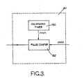
- This digital signal which is a square wave signal whose frequency is proportioned to the monitored vibration amplitude, is sampled by the timer 30 which is shown in detail in Figure 3 and comprises a countdown timer 50 and pulse counter 52.
- the output of the converter 28 is fed to the pulse counter 52 which is "gated” by gate pulses from the countdown timer 50.
- Each gate pulse is preferably 80ms duration at an interval of 80ms to provide 12 pulses/second.
- the pulse counter 52 counts the number of input pulses over the 80ms period and this count is then multiplied by the microprocessor 32 by a preset factor to give a High Trip level (HT L ).
- the factor has previously been input either by an operator or by the machine tool control system programme.
- the HTL number is then compared by the microprocessor 32 with a preset number, in this instance 65000.- If the HTL is less than 65000 then the attenuator gain is increased by 1 and the process _repeated to give a new HTL. If HTL is greater than 65000 or the attenuator gain is maximum then, provided the gain is not 1, the gain is reduced by 1, the new HTL calculated for this new gain and stored in the system memory together with the attenuator gain and selected filter band to provide a machining "signature". If desired, a second, lower trip level (LTL) is also generated as a preselected function of HTL and stored. This can be used to warn that a tool is approaching the end of its useful life.
- LTL lower trip level
- a machining "signature” is then available for use in all machining operations in which the same machining conditions apply so that when a machining operation is commenced in which the same or similar machining conditions apply the filter 22, gain of the attenuator, HTL and LTL are automatically set according to the relevant "signature” which is called from the memory by the microprocessor.
- the vibration level monitored by the system is compared with preselected minimum reference level and, if the monitored level remains lower than the reference level for a preselected time period, indicating that the tool is not cutting when it should be, the machining operation is aborted. If the monitored vibration level reaches the minimum reference level then machining continues until the monitored vibration level reaches the lower trip level which triggers a warning that the tool is approaching the end of its useful life. When the monitored vibration level reaches the higher trip level then the machine operation is automatically stopped and, where appropriate, a tool change operation actuated.
- the same procedure is applied for each type of machining operation carried out on a workpiece and if the higher trip level is not reached during a machining operation effected on the first workpiece then that machining operation is repeated on the next and successive workpieces using the same tool and "signature". If a tool is replaced by an identical tool for machining the same workpiece type the same stored "signature” is used and the machining operation proceeds as described, although a new "signature” could be generated if desired.
- the first trip level can also be used to initiate a tool change, if desired.
- the system is described as being designed to monitor via a single sensor 12 the vibration of a number of cutting tools used sequentially, it will be appreciated that the system can be altered to monitor simultaneous machining operations using several parallel sensors.
- the sensors can be on a single machine tool with multiple spindle heads or on several machine tools each having single or multiple spindle heads.
- the relevant "signatures”, i.e. datum and trip levels are established for the respective machining conditions as is described above with reference to Figure .1 and then each time a machining condition is repeated the actual vibration level is compared only with the relevant "signature".
- sensors 12.are used these are coupled through a multiplexer 16 to the attenuator, the sensor outputs being coupled sequentially under the control of the microprocessor 32.
- the maximum tool vibration levels which are monitored are stored and the microprocessor scans the stored values sequentially to compare them with the reference "signature".
- the advantage of this is that it reduces the time during which the vibration level of any one tool is not being compared with its "signature”. This is particularly important in detecting breakage of a tool since an undetected broken tool can do considerable damage in a very short time.
- the vibration of a cutting tool which is monitored by an apparatus according to the present invention can be any type of mechanical signal produced by the tool during use.
- Various transducers are available which permit monitoring of displacement, velocity or acceleration.
- a preferred form is a piezo-electric accelerometer sensor.
- Another type of sensor uses so-called acoustic emission which is a term applied to the low level stress wave emitted by a solid material when it is deformed or ruptured in association with relief of strain energies.
- the detection of acoustic emission is conveniently effected using an acoustic emission sensor attached to the tool shank, toolholder or machine tool spindle head to provide an electrical signal representative of the detected vibration. The signal can then be processed in the normal manner.
- the advantage of acoustic emission measurement is that it is far more sensitive to the monitoring of the production of cracks, chips and the like in tools.
Landscapes
- Engineering & Computer Science (AREA)
- Physics & Mathematics (AREA)
- General Physics & Mathematics (AREA)
- Analytical Chemistry (AREA)
- General Health & Medical Sciences (AREA)
- Human Computer Interaction (AREA)
- Automation & Control Theory (AREA)
- Health & Medical Sciences (AREA)
- Life Sciences & Earth Sciences (AREA)
- Chemical & Material Sciences (AREA)
- Mechanical Engineering (AREA)
- Biochemistry (AREA)
- Manufacturing & Machinery (AREA)
- Immunology (AREA)
- Pathology (AREA)
- Automatic Control Of Machine Tools (AREA)
- Machine Tool Sensing Apparatuses (AREA)
- Measurement Of Mechanical Vibrations Or Ultrasonic Waves (AREA)
- Lubricants (AREA)
- Crystals, And After-Treatments Of Crystals (AREA)
- Cutting Tools, Boring Holders, And Turrets (AREA)
- Indicating And Signalling Devices For Elevators (AREA)
Priority Applications (1)
| Application Number | Priority Date | Filing Date | Title |
|---|---|---|---|
| AT84300159T ATE34616T1 (de) | 1983-01-12 | 1984-01-11 | Geraet zur ueberwachung der werkzeuglebensdauer. |
Applications Claiming Priority (2)
| Application Number | Priority Date | Filing Date | Title |
|---|---|---|---|
| GB838300792A GB8300792D0 (en) | 1983-01-12 | 1983-01-12 | Monitoring tool life |
| GB8300792 | 1983-01-12 |
Publications (2)
| Publication Number | Publication Date |
|---|---|
| EP0119680A1 true EP0119680A1 (de) | 1984-09-26 |
| EP0119680B1 EP0119680B1 (de) | 1988-05-25 |
Family
ID=10536251
Family Applications (1)
| Application Number | Title | Priority Date | Filing Date |
|---|---|---|---|
| EP84300159A Expired EP0119680B1 (de) | 1983-01-12 | 1984-01-11 | Gerät zur Überwachung der Werkzeuglebensdauer |
Country Status (5)
| Country | Link |
|---|---|
| US (1) | US4563897A (de) |
| EP (1) | EP0119680B1 (de) |
| AT (1) | ATE34616T1 (de) |
| DE (1) | DE3471523D1 (de) |
| GB (1) | GB8300792D0 (de) |
Cited By (7)
| Publication number | Priority date | Publication date | Assignee | Title |
|---|---|---|---|---|
| EP0196567A3 (en) * | 1985-04-05 | 1987-10-14 | International Business Machines Corporation | Apparatus and method for monitoring the operating condition of a drill bit |
| GB2199949A (en) * | 1986-12-19 | 1988-07-20 | Gen Electric | Automatic gain control for acoustic tool break detector |
| EP0165482A3 (en) * | 1984-05-18 | 1988-09-21 | Omron Tateisi Electronics Co. | Tool monitoring system tool monitoring system |
| GB2204406A (en) * | 1987-05-07 | 1988-11-09 | Gen Electric | Detection by automatic gain control features of both sudden and gradual cutting tool breakage |
| GB2176606B (en) * | 1985-06-12 | 1989-12-06 | Gen Electric | Methods of optimizing the performance of machine tool monitors |
| FR2659891A1 (fr) * | 1990-03-26 | 1991-09-27 | Ntn Toyo Bearing Co Ltd | Dispositif de detection d'anomalie d'outil pour machine-outil. |
| WO1992004663A1 (de) * | 1990-08-31 | 1992-03-19 | Henri Hauser Ag | Einrichtung zur ueberwachung und steuerung einer schleifmaschine und verfahren zum betrieb derselben |
Families Citing this family (29)
| Publication number | Priority date | Publication date | Assignee | Title |
|---|---|---|---|---|
| US4642617A (en) * | 1984-12-21 | 1987-02-10 | General Electric Company | Acoustic tool break detection system and method |
| US4736625A (en) * | 1986-11-05 | 1988-04-12 | The Warner & Swasey Company | Method and apparatus for monitoring the cutting condition of a machine tool during machining of a workpiece |
| US4807167A (en) * | 1987-03-18 | 1989-02-21 | General Electric Company | Rapid method of digital automatic gain control |
| US4831365A (en) * | 1988-02-05 | 1989-05-16 | General Electric Company | Cutting tool wear detection apparatus and method |
| US4854161A (en) * | 1988-06-28 | 1989-08-08 | Innovex Inc. | Method for diagnosing cutting tool dullness |
| GB8826640D0 (en) * | 1988-11-15 | 1988-12-21 | Sensotect Ltd | Apparatus for determining surface roughness of material |
| DE3907419A1 (de) * | 1989-03-08 | 1990-09-13 | Ingenieurgesellschaft Fuer Beh | Verfahren zur schadensverhuetung an einer maschine oder vorrichtung |
| US4922754A (en) * | 1989-03-17 | 1990-05-08 | Kennametal Inc. | Acoustic emission transducer and mounting adapter for monitoring metalcutting tools |
| US5187669A (en) * | 1990-07-16 | 1993-02-16 | General Electric Company | Programmable surface sensor for machining rough stock |
| EP0607221B1 (de) * | 1991-10-10 | 1999-12-01 | Finn-Power International, Inc. | Verfahren und gerät zum sichern der korrekten bearbeitung einer folie |
| US5663894A (en) * | 1995-09-06 | 1997-09-02 | Ford Global Technologies, Inc. | System and method for machining process characterization using mechanical signature analysis |
| US5739433A (en) * | 1996-03-01 | 1998-04-14 | University Of Central Florida | Touch off probe |
| AU3310297A (en) * | 1996-06-26 | 1998-01-14 | Gleason Works, The | Detecting tool wear by thermal monitoring of workpiece |
| US5852793A (en) * | 1997-02-18 | 1998-12-22 | Dme Corporation | Method and apparatus for predictive diagnosis of moving machine parts |
| JPH11296213A (ja) * | 1998-04-07 | 1999-10-29 | Fanuc Ltd | 機械装置 |
| US6633379B2 (en) * | 2001-06-08 | 2003-10-14 | Semiconductor 300 Gmbh & Co. Kg | Apparatus and method for measuring the degradation of a tool |
| US7341410B2 (en) * | 2003-03-10 | 2008-03-11 | Foster-Miller, Inc. | Dynamical instrument for machining |
| US7287177B2 (en) * | 2003-12-04 | 2007-10-23 | International Business Machines Corporation | Digital reliability monitor having autonomic repair and notification capability |
| US20050144524A1 (en) * | 2003-12-04 | 2005-06-30 | International Business Machines Corporation | Digital reliability monitor having autonomic repair and notification capability |
| DE102007039570A1 (de) * | 2006-09-04 | 2008-03-06 | Robert Bosch Gmbh | Werkzeugmaschinenüberwachungsvorrichtung |
| US7424338B1 (en) | 2007-04-02 | 2008-09-09 | Honda Motor Co., Ltd. | Broken tool detection system |
| US20090129882A1 (en) * | 2007-11-15 | 2009-05-21 | D4D Technologies, Llc | Methods, Systems, and Devices for Monitoring Tools in a Dental Milling Machine |
| JP6201565B2 (ja) * | 2013-09-24 | 2017-09-27 | アイシン精機株式会社 | 歯車製造方法 |
| US10295475B2 (en) | 2014-09-05 | 2019-05-21 | Rolls-Royce Corporation | Inspection of machined holes |
| US9945755B2 (en) * | 2014-09-30 | 2018-04-17 | Marquip, Llc | Methods for using digitized sound patterns to monitor operation of automated machinery |
| US10228669B2 (en) | 2015-05-27 | 2019-03-12 | Rolls-Royce Corporation | Machine tool monitoring |
| US9984551B2 (en) * | 2016-03-15 | 2018-05-29 | Ashworth Bros., Inc. | System and method for anticipating low-speed bearing failure |
| US10195708B2 (en) * | 2016-09-28 | 2019-02-05 | The Boeing Company | Method and apparatus for centralized compliance, operations and setup of automated cutting tool machines |
| JP7194965B2 (ja) * | 2018-08-01 | 2022-12-23 | 中村留精密工業株式会社 | 工作機械 |
Citations (10)
| Publication number | Priority date | Publication date | Assignee | Title |
|---|---|---|---|---|
| GB1441948A (en) * | 1973-01-08 | 1976-07-07 | Interactive Systems | Tool wear detectors |
| GB1480353A (en) * | 1973-08-31 | 1977-07-20 | Vyzk Ustav Obrabecich Stroju | Method and a device for the determination of wear of a tool |
| CH591691A5 (de) * | 1974-12-20 | 1977-09-30 | Tokyo Shibaura Electric Co | |
| GB1504310A (en) * | 1975-12-31 | 1978-03-15 | Tokyo Shibaura Electric Co | Apparatus for measuring the condition of a tool |
| US4120196A (en) * | 1977-03-25 | 1978-10-17 | The Charles Stark Draper Laboratory, Inc. | Production tool wear detector |
| DE2916703A1 (de) * | 1978-04-26 | 1979-10-31 | Fujitsu Fanuc Ltd | Werkzeugverschleiss-feststellsystem |
| DE2840542A1 (de) * | 1978-05-30 | 1979-12-06 | Komatsu Mfg Co Ltd | Vorrichtung zur abtastung von schneidspitzen-beschaedigungen eines fraeswerkzeugs |
| GB2051362A (en) * | 1979-05-23 | 1981-01-14 | Production Eng Research Ass Og | Monitoring tool life |
| DE3029957A1 (de) * | 1980-08-07 | 1982-02-25 | Siemens AG, 1000 Berlin und 8000 München | Verfahren und anordnung zur feststellung von werkzeugverschleiss |
| EP0079801A2 (de) * | 1981-11-18 | 1983-05-25 | Automation Intelligence, Inc. | Vorrichtung zur Verschleiss- und Bruchkontrolle eines Werkzeugs |
Family Cites Families (2)
| Publication number | Priority date | Publication date | Assignee | Title |
|---|---|---|---|---|
| US3872285A (en) * | 1974-05-31 | 1975-03-18 | Westinghouse Electric Corp | Control system for sensing the vibration and lateral force on a cutting tool |
| US4471444A (en) * | 1982-04-02 | 1984-09-11 | The United States Of America As Represented By The Secretary Of Commerce | Rotating tool wear monitoring apparatus |
-
1983
- 1983-01-12 GB GB838300792A patent/GB8300792D0/en active Pending
-
1984
- 1984-01-11 AT AT84300159T patent/ATE34616T1/de not_active IP Right Cessation
- 1984-01-11 DE DE8484300159T patent/DE3471523D1/de not_active Expired
- 1984-01-11 EP EP84300159A patent/EP0119680B1/de not_active Expired
- 1984-01-12 US US06/570,180 patent/US4563897A/en not_active Expired - Fee Related
Patent Citations (11)
| Publication number | Priority date | Publication date | Assignee | Title |
|---|---|---|---|---|
| GB1441948A (en) * | 1973-01-08 | 1976-07-07 | Interactive Systems | Tool wear detectors |
| GB1480353A (en) * | 1973-08-31 | 1977-07-20 | Vyzk Ustav Obrabecich Stroju | Method and a device for the determination of wear of a tool |
| CH591691A5 (de) * | 1974-12-20 | 1977-09-30 | Tokyo Shibaura Electric Co | |
| GB1504310A (en) * | 1975-12-31 | 1978-03-15 | Tokyo Shibaura Electric Co | Apparatus for measuring the condition of a tool |
| US4120196A (en) * | 1977-03-25 | 1978-10-17 | The Charles Stark Draper Laboratory, Inc. | Production tool wear detector |
| DE2916703A1 (de) * | 1978-04-26 | 1979-10-31 | Fujitsu Fanuc Ltd | Werkzeugverschleiss-feststellsystem |
| GB2022262A (en) * | 1978-04-26 | 1979-12-12 | Fujitsu Fanuc Ltd | Tool wear detection |
| DE2840542A1 (de) * | 1978-05-30 | 1979-12-06 | Komatsu Mfg Co Ltd | Vorrichtung zur abtastung von schneidspitzen-beschaedigungen eines fraeswerkzeugs |
| GB2051362A (en) * | 1979-05-23 | 1981-01-14 | Production Eng Research Ass Og | Monitoring tool life |
| DE3029957A1 (de) * | 1980-08-07 | 1982-02-25 | Siemens AG, 1000 Berlin und 8000 München | Verfahren und anordnung zur feststellung von werkzeugverschleiss |
| EP0079801A2 (de) * | 1981-11-18 | 1983-05-25 | Automation Intelligence, Inc. | Vorrichtung zur Verschleiss- und Bruchkontrolle eines Werkzeugs |
Cited By (9)
| Publication number | Priority date | Publication date | Assignee | Title |
|---|---|---|---|---|
| EP0165482A3 (en) * | 1984-05-18 | 1988-09-21 | Omron Tateisi Electronics Co. | Tool monitoring system tool monitoring system |
| EP0196567A3 (en) * | 1985-04-05 | 1987-10-14 | International Business Machines Corporation | Apparatus and method for monitoring the operating condition of a drill bit |
| GB2176606B (en) * | 1985-06-12 | 1989-12-06 | Gen Electric | Methods of optimizing the performance of machine tool monitors |
| GB2199949A (en) * | 1986-12-19 | 1988-07-20 | Gen Electric | Automatic gain control for acoustic tool break detector |
| GB2199949B (en) * | 1986-12-19 | 1991-03-27 | Gen Electric | Automatic gain control for machine tool monitor |
| GB2204406A (en) * | 1987-05-07 | 1988-11-09 | Gen Electric | Detection by automatic gain control features of both sudden and gradual cutting tool breakage |
| GB2204406B (en) * | 1987-05-07 | 1991-05-01 | Gen Electric | Detection by automatic gain control features of gradual cutting tool breakage |
| FR2659891A1 (fr) * | 1990-03-26 | 1991-09-27 | Ntn Toyo Bearing Co Ltd | Dispositif de detection d'anomalie d'outil pour machine-outil. |
| WO1992004663A1 (de) * | 1990-08-31 | 1992-03-19 | Henri Hauser Ag | Einrichtung zur ueberwachung und steuerung einer schleifmaschine und verfahren zum betrieb derselben |
Also Published As
| Publication number | Publication date |
|---|---|
| DE3471523D1 (en) | 1988-06-30 |
| ATE34616T1 (de) | 1988-06-15 |
| US4563897A (en) | 1986-01-14 |
| EP0119680B1 (de) | 1988-05-25 |
| GB8300792D0 (en) | 1983-02-16 |
Similar Documents
| Publication | Publication Date | Title |
|---|---|---|
| EP0119680B1 (de) | Gerät zur Überwachung der Werkzeuglebensdauer | |
| EP0079801B1 (de) | Vorrichtung zur Verschleiss- und Bruchkontrolle eines Werkzeugs | |
| US4351029A (en) | Tool life monitoring and tracking apparatus | |
| RU2180967C2 (ru) | Автоматический текущий контроль состояния инструмента | |
| KR100579083B1 (ko) | 공작기계의 공구 이상 검출장치 및 검출방법 | |
| US4471444A (en) | Rotating tool wear monitoring apparatus | |
| US4831365A (en) | Cutting tool wear detection apparatus and method | |
| EP0093558B1 (de) | Einrichtung zum vorzeitigen Erkennen einer möglichen Anomalie eines Schneidewerkzeuges | |
| US4332161A (en) | Acoustic detection of tool wear and fracture | |
| GB2243037A (en) | Machine tool load abnormality detecting device with stored threshold pattern | |
| GB2133881A (en) | Apparatus for monitoring tool life | |
| JP3446518B2 (ja) | 回転工具の異常検出方法およびその装置 | |
| US5773949A (en) | Cutter fracture detecting system | |
| Thangaraj et al. | Drill wear sensing and failure prediction for untended machining | |
| Liao | Development of a monitoring technique for tool change purpose in turning operations | |
| Novak et al. | Reliability of the cutting force monitoring in FMS-installations | |
| JPS6059108B2 (ja) | 工作機の異常監視装置 | |
| JP2629695B2 (ja) | 切削加工機械における監視装置 | |
| JPH06320396A (ja) | 刃工具の寿命判定方法および自動交換方法 | |
| JPS63200944A (ja) | 切削加工機械における送り速度制御装置 | |
| JPH04189447A (ja) | 切削機械の制御装置 | |
| JPS59201748A (ja) | 切削用工具欠損検出装置 | |
| JP2520017B2 (ja) | 穴明加工における加工負荷監視方法及びその装置 | |
| JPS61217759A (ja) | 工具折損検出装置 | |
| JPH0132023B2 (de) |
Legal Events
| Date | Code | Title | Description |
|---|---|---|---|
| PUAI | Public reference made under article 153(3) epc to a published international application that has entered the european phase |
Free format text: ORIGINAL CODE: 0009012 |
|
| AK | Designated contracting states |
Designated state(s): AT BE CH DE FR IT LI LU NL SE |
|
| 17P | Request for examination filed |
Effective date: 19850325 |
|
| 17Q | First examination report despatched |
Effective date: 19860411 |
|
| GRAA | (expected) grant |
Free format text: ORIGINAL CODE: 0009210 |
|
| AK | Designated contracting states |
Kind code of ref document: B1 Designated state(s): AT BE CH DE FR IT LI LU NL SE |
|
| PG25 | Lapsed in a contracting state [announced via postgrant information from national office to epo] |
Ref country code: LI Effective date: 19880525 Ref country code: CH Effective date: 19880525 |
|
| REF | Corresponds to: |
Ref document number: 34616 Country of ref document: AT Date of ref document: 19880615 Kind code of ref document: T |
|
| PG25 | Lapsed in a contracting state [announced via postgrant information from national office to epo] |
Ref country code: SE Effective date: 19880531 |
|
| REF | Corresponds to: |
Ref document number: 3471523 Country of ref document: DE Date of ref document: 19880630 |
|
| ITF | It: translation for a ep patent filed | ||
| REG | Reference to a national code |
Ref country code: CH Ref legal event code: PL |
|
| ET | Fr: translation filed | ||
| PLBE | No opposition filed within time limit |
Free format text: ORIGINAL CODE: 0009261 |
|
| STAA | Information on the status of an ep patent application or granted ep patent |
Free format text: STATUS: NO OPPOSITION FILED WITHIN TIME LIMIT |
|
| 26N | No opposition filed | ||
| PG25 | Lapsed in a contracting state [announced via postgrant information from national office to epo] |
Ref country code: NL Effective date: 19890801 |
|
| NLV4 | Nl: lapsed or anulled due to non-payment of the annual fee | ||
| PGFP | Annual fee paid to national office [announced via postgrant information from national office to epo] |
Ref country code: FR Payment date: 19910110 Year of fee payment: 8 |
|
| PGFP | Annual fee paid to national office [announced via postgrant information from national office to epo] |
Ref country code: AT Payment date: 19910111 Year of fee payment: 8 |
|
| PGFP | Annual fee paid to national office [announced via postgrant information from national office to epo] |
Ref country code: BE Payment date: 19910124 Year of fee payment: 8 |
|
| PGFP | Annual fee paid to national office [announced via postgrant information from national office to epo] |
Ref country code: LU Payment date: 19910128 Year of fee payment: 8 |
|
| ITTA | It: last paid annual fee | ||
| PGFP | Annual fee paid to national office [announced via postgrant information from national office to epo] |
Ref country code: DE Payment date: 19910131 Year of fee payment: 8 |
|
| EPTA | Lu: last paid annual fee | ||
| PG25 | Lapsed in a contracting state [announced via postgrant information from national office to epo] |
Ref country code: LU Free format text: LAPSE BECAUSE OF NON-PAYMENT OF DUE FEES Effective date: 19920111 Ref country code: AT Effective date: 19920111 |
|
| PG25 | Lapsed in a contracting state [announced via postgrant information from national office to epo] |
Ref country code: BE Effective date: 19920131 |
|
| BERE | Be: lapsed |
Owner name: THE PRODUCTION ENGINEERING RESEARCH ASSOCIATION Effective date: 19920131 |
|
| PG25 | Lapsed in a contracting state [announced via postgrant information from national office to epo] |
Ref country code: FR Effective date: 19920930 |
|
| PG25 | Lapsed in a contracting state [announced via postgrant information from national office to epo] |
Ref country code: DE Effective date: 19921001 |
|
| REG | Reference to a national code |
Ref country code: FR Ref legal event code: ST |