EP0119687A1 - Appareil de distribution de serviettes - Google Patents
Appareil de distribution de serviettes Download PDFInfo
- Publication number
- EP0119687A1 EP0119687A1 EP84300380A EP84300380A EP0119687A1 EP 0119687 A1 EP0119687 A1 EP 0119687A1 EP 84300380 A EP84300380 A EP 84300380A EP 84300380 A EP84300380 A EP 84300380A EP 0119687 A1 EP0119687 A1 EP 0119687A1
- Authority
- EP
- European Patent Office
- Prior art keywords
- roller
- towel
- body portion
- engageable
- towelling
- Prior art date
- Legal status (The legal status is an assumption and is not a legal conclusion. Google has not performed a legal analysis and makes no representation as to the accuracy of the status listed.)
- Granted
Links
Images


Classifications
-
- A—HUMAN NECESSITIES
- A47—FURNITURE; DOMESTIC ARTICLES OR APPLIANCES; COFFEE MILLS; SPICE MILLS; SUCTION CLEANERS IN GENERAL
- A47K—SANITARY EQUIPMENT; ACCESSORIES THEREFOR, e.g. TOILET ACCESSORIES
- A47K10/00—Body-drying implements; Toilet paper; Holders therefor
- A47K10/24—Towel dispensers; Toilet paper dispensers
- A47K10/28—Towel dispensers; Toilet paper dispensers dispensing a clean part and taking-up a soiled part, e.g. using rolls; with dispensers for soap or other detergents; with disinfecting or heating devices
Definitions
- This invention relates to rollers for use in towel dispensing apparatus such as, for example, towel dispensing apparatus of the kind used in towel-dispensing cabinets employing a roll of towelling which is dispensed from the cabinet in successive portions in response to a pulling action by the user, and the used towelling is likewise continuously taken up into the cabinet.
- the invention also provides towel dispensing apparatus incorporating such rollers.
- the principal dispensing rollers which control the length of towel dispensed in response to a pull by the user, and which also control the take-up of the used towelling, are formed as metal fabrications with a surface layer of emery paper bonded thereto by a suitable adhesive.
- An object of the present invention is to provide a roller for a towel dispensing mechanism offering improvements in relation to one or more of the above-identified technical problems.
- a towel-engageable roller for a towel dispensing mechanism having a towel-engageable surface comprising a polymeric material.
- a towel-engageable roller for a towel dispensing mechanism, the roller having a towel-engageable surface layer drivably coupled to the body of the roller by mechanical means.
- the towel-engageable surface of the roller comprises an elastomer.
- the elastomer is preferably natural rubber.
- the towel engageable surface of the roller may comprise one or more spaced bands comprising elastomeric material.
- the towel-engageable surface may be formed with a surface pattern or tread to improve the grip thereof in relation to the towel.
- the surface pattern or tread may comprise axially extending ribs and grooves, or flutes.
- the towel engageable surface of the roller may comprise a band formed with an internal drive formation to co-operate with a complementary formation on the body of the roller.
- Said internal drive formation may comprise a key or rib member on said band to co-operate with an external groove on the roller body to receive said key or rib.
- Two or more key or rib members may be provided, preferably 4.
- the or each rib member may extend axially of the roller along only a portion of the axial length of the band.
- the main body of the roller may itself comprise a polymeric material, such as polyvinylchloride.
- the main body may be in the form of a tube.
- End support members for the roller may be formed from a polymeric material to be received in respective bearing assemblies.
- the end support members may be bonded to the body of the tube.
- the invention also provides any concept or feature or combination of features defined and/or described and/or illustrated in this specification and drawings.
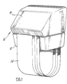
- a towel dispensing cabinet 10 contains towel dispensing apparatus 12 for dispensing a long roll of towel 14.
- Cabinet 10 comprises hinged upper and lower cabinet portions 16, 18 respectively which are openable to permit new and used rolls of towelling to be inserted into and removed from the cabinet.
- the path of a towel during use is as follows.
- the roll of clean towel 20 is contained in the cabinet lower portion or bottom bucket 18 and the towel. extends from the roll in an upwards run 22 to a floating roller 24.
- the towel passes into the nip 26 between floating roller 24 and first main towel roller 28 and then passes anti-clockwise round floating roller 24 and downwards through the dispensing slot 30 in the cabinet and thence to the towel loop portion 32 where a user dries his or her hands on the towel.
- From loop 32 the towel passes upwards through a rear opening 34 back into the cabinet and passes anti-clockwise round a second floating roller 36 and into the nip 38 between floating roller 36 and a second main towel roller 40.
- the towel is mounted on floating roller 36 so as to wind-up thereon, and this roller thus provides towel take-up and the entire length of towelling is eventually wound onto roller 36 after use, the roller floating 'upwards to accommodate the increasing diameter of the roll of towelling thereon.
- End sprockets 42 and 44 are provided at the ends of the main towel rollers 28 and 40 respectively, the sprockets being connected by a chain 46.
- a downward pull in the direction P by a user on the loop portion 32 of the towel causes floating roller 24 to press against roller 28 so that the towel is firmly gripped between rollers 24, 28 and drive is transmitted to roller 28 and thence via chain 46 to the second main towel roller 40.
- the latter roller frictionally engages the second floating roller 36 causing the latter to rotate and to take-up the used towelling at the same rate that it is dispensed, whereby towel loop 32 remains at a constant length throughout the period of use.
- a limiting mechanism 48 is provided to limit the length of towel which can be obtained by a user at a single pull on towel loop portion 32.
- Limiting mechanism 48 comprises a roller cam arm 50 rotatable with sprocket 44 on the second main towel roller 40, a pivoted stop lever 52, a ratchet wheel 54 and a delay mechanism 56.
- Cam arm 50 engages a cam surface 5-8 on stop lever 52 so as to pivot the latter anti-clockwise about pivot axis 60, thereby bringing stop 62 at the end of lever 52 into engagement with one of the teeth of ratchet wheel 54 and also bringing suction cups 64, 66 of delay mechanism 56 into vacuum engagement.
- the towel rollers are prevented from rotating and the user can obtain no more clean towelling.
- the vacuum between suction cups 64, 66 collapses, the suction cups part and stop lever 52 returns to the position shown in Fig 2 and further towel can be obtained by the next user.
- the present invention is concerned in this embodiment with the construction of the first and second main towel rollers 28 and 40, the floating rollers 24 and 36 being of plastics material with a smooth surface finish.
- the roller constructions described below in relation to the first and second main rollers could likewise be adopted for the floating rollers, with modifications if necessary or if desired.
- roller 28 comprises a tubular roller body portion 70, end supports 72, 74 and towel-engageable bands 76, 78.
- Roller body portion 70 is formed from polyvinylchloride, or other suitable plastics material or mixture of such materials whether reinforced or otherwise, and is of tubular cylindrical form with a smooth cylindrical external surface 80. Roller body portion 70 may be formed as an extruded tube which is cut to length for roller construction purposes, or a solid cylinder may be used instead.
- Each groove extends along the full length of body portion 70 and is of generally V-shaped cross section and of depth approximately half the thickness of the material of body portion 70, as shown in Fig 5.
- End supports 72, 74 are each in the form of a moulded plastic component formed in one piece from nylon or an alternative plastics material and serve to support roller 28 for rotation about its longitudinal axis 84 in bearing assemblies (not shown) carried by end plates 86, 88 of the towel dispensing apparatus 12.
- Each end support comprises an end cap 90 moulded in one piece with a stub shaft 92.
- End caps 90 are shaped and proportioned to fit into the inside surface 94 of roller body portion 70 and are bonded or welded thereto so that stub shafts 92 are co-axial.
- Towel-engageable bands 76, 78 are identical in structure and each comprises a fluted or ribbed portion 96 for engagement with a towel being dispensed, and 4 internal ribs 98 for entry into and driving engagement with grooves 82 in surface 80 of roller body portion 70.
- Bands 76, 78 are formed of natural rubber. Other elastomeric materials or combinations thereof may be devised which are suitable, including synthetic elastomers, with a variety of surface patterns or treads formed on the external towel-engaging surfaces of the bands.
- Fig 5 shows the structure of the axially extending ribs 100 formed on the external surface of band 76, 78.
- the ribs extend along the full axial length of each band and provide a high friction surface for engagement with and gripping of the towel being dispensed.
- Internal ribs 98 enter grooves 82 in the roller and provide positive mechanical transmission of drive from the roller body portion to the bands themselves, without the use of any adhesive. It will be noted that the axial length of the internal ribs 98 is less than the full axial length of the bands, and indeed is less than half such axial length, which simplifies manufacture and assembly.
- a pull by a user on loop 32 of the towel causes a downward load on floating roller 24, thereby squeezing the towel between the latter roller and first main towel roller 28.
- the ribs surface of bands 76, 78 on the latter roller frictionally engage and grip the towel whereby the roller rotates anti-clockwise, as seen in Fig 2 and clean towel is dispensed through slot 30 and chain 46 transmits drive to sprocket 44 and hence to the stub shaft 92 at that end of second main towel roller 40.
- limiting mechanism 48 stops rotation of the rollers 28, 40, then, after a short delay, further towel can be obtained by another user.
- the used towel passes around the second floating roller 36 and is wound up thereon.
- the drive transmitted to second main roller 40 causes the latter to rotate and the ribs 100 on its bands 76, 78 engage and grip the towel and cause it to be positively wound onto roller 36 at the same rate that the towel is dispensed through slot 30. Eventually the entire towel becomes, after use, wound onto roller 36.
- rollers 28, 40 are simple and relatively inexpensive to manufacture and assemble, avoiding the use of any significant amounts of adhesive and the like.
- moulded end support 72, 74 formed of a plastics material further simplifies manufacture.
- Previous roller constructions have involved fabrication of the end supports from a number of metal components. Such fabrication has inherently tended to introduce tolerances in the roller construction.
- the use of moulded end supports as described above reduces significantly the likelihood of unacceptable tolerances being introduced in the end support assembly.
- the bands, 76, 78 these could be modified by the use of only one band of greater axial length or by the use of 3 or more such bands.
- the form of the ribs 100 may be varied considerably and many other surface patterns or treads may be found to be acceptable, including non-axial formations.
- the internal ribs 98 the number of these may be varied down to one only and more than 4 may be employed if desired.
- the ribs may extend along a greater or smaller proportion of the axial length of the bands than that shown in Fig 4, and other methods of mechanically keying the bands to the roller body portions may be employed. Indeed, mechanical keying is not an essential feature of the invention and a drivable coupling may be provided by other mechanical means.
- the invention is of course applicable to many different kinds of towel dispensing mechanism other than the particular one described in relation to Figs 2 and 3.
Landscapes
- Health & Medical Sciences (AREA)
- Public Health (AREA)
- Body Washing Hand Wipes And Brushes (AREA)
- Containers And Packaging Bodies Having A Special Means To Remove Contents (AREA)
- Unwinding Webs (AREA)
- Feeding, Discharge, Calcimining, Fusing, And Gas-Generation Devices (AREA)
- Confectionery (AREA)
Priority Applications (1)
| Application Number | Priority Date | Filing Date | Title |
|---|---|---|---|
| AT84300380T ATE26531T1 (de) | 1983-02-19 | 1984-01-23 | Handtuchspender. |
Applications Claiming Priority (2)
| Application Number | Priority Date | Filing Date | Title |
|---|---|---|---|
| GB838304680A GB8304680D0 (en) | 1983-02-19 | 1983-02-19 | Dispensing apparatus |
| GB8304680 | 1983-02-19 |
Publications (2)
| Publication Number | Publication Date |
|---|---|
| EP0119687A1 true EP0119687A1 (fr) | 1984-09-26 |
| EP0119687B1 EP0119687B1 (fr) | 1987-04-15 |
Family
ID=10538303
Family Applications (1)
| Application Number | Title | Priority Date | Filing Date |
|---|---|---|---|
| EP84300380A Expired EP0119687B1 (fr) | 1983-02-19 | 1984-01-23 | Appareil de distribution de serviettes |
Country Status (6)
| Country | Link |
|---|---|
| US (1) | US4579398A (fr) |
| EP (1) | EP0119687B1 (fr) |
| AT (1) | ATE26531T1 (fr) |
| DE (1) | DE3463118D1 (fr) |
| GB (1) | GB8304680D0 (fr) |
| ZA (1) | ZA84592B (fr) |
Cited By (1)
| Publication number | Priority date | Publication date | Assignee | Title |
|---|---|---|---|---|
| EP0532808A1 (fr) * | 1991-09-19 | 1993-03-24 | Sunpac Co Ltd | Rouleau |
Families Citing this family (3)
| Publication number | Priority date | Publication date | Assignee | Title |
|---|---|---|---|---|
| US6736466B1 (en) | 2002-08-27 | 2004-05-18 | Steven R. Helland | Paper towel dispensing apparatus |
| US9028502B2 (en) | 2011-09-23 | 2015-05-12 | Greatbatch Medical S.A. | Ceramic implant holder |
| US11769363B1 (en) * | 2022-10-31 | 2023-09-26 | The Tranzonic Companies | Feminine hygiene product dispenser with trigger |
Citations (4)
| Publication number | Priority date | Publication date | Assignee | Title |
|---|---|---|---|---|
| GB732768A (en) * | 1953-12-21 | 1955-06-29 | Geoffrey Knox | Improved apparatus for dispensing sheet material from a continuous web |
| GB1112546A (en) * | 1965-04-09 | 1968-05-08 | Schumm Erich | Improvements in and relating to towel dispensers |
| US3858953A (en) * | 1973-10-01 | 1975-01-07 | Steiner American Corp | Towel dispenser |
| US4170390A (en) * | 1978-03-09 | 1979-10-09 | Mccabe Stanley G | Paper towel dispenser |
Family Cites Families (5)
| Publication number | Priority date | Publication date | Assignee | Title |
|---|---|---|---|---|
| US3339818A (en) * | 1965-06-08 | 1967-09-05 | United States Steel Corp | Self-centering roll |
| US3441463A (en) * | 1965-10-24 | 1969-04-29 | Schjeldahl Co G T | Coverlay encapsulation for printed wiring |
| US3508773A (en) * | 1967-06-12 | 1970-04-28 | Kobe Inc | Friction-type rod joint |
| US3871777A (en) * | 1972-12-22 | 1975-03-18 | L E Sauer Machine Co | Clamping means for split rotary anvil and the like |
| US4217061A (en) * | 1977-06-30 | 1980-08-12 | Abram N. Spanel | Tapered key coupling |
-
1983
- 1983-02-19 GB GB838304680A patent/GB8304680D0/en active Pending
-
1984
- 1984-01-23 EP EP84300380A patent/EP0119687B1/fr not_active Expired
- 1984-01-23 DE DE8484300380T patent/DE3463118D1/de not_active Expired
- 1984-01-23 AT AT84300380T patent/ATE26531T1/de not_active IP Right Cessation
- 1984-01-26 ZA ZA84592A patent/ZA84592B/xx unknown
- 1984-02-09 US US06/578,667 patent/US4579398A/en not_active Expired - Fee Related
Patent Citations (4)
| Publication number | Priority date | Publication date | Assignee | Title |
|---|---|---|---|---|
| GB732768A (en) * | 1953-12-21 | 1955-06-29 | Geoffrey Knox | Improved apparatus for dispensing sheet material from a continuous web |
| GB1112546A (en) * | 1965-04-09 | 1968-05-08 | Schumm Erich | Improvements in and relating to towel dispensers |
| US3858953A (en) * | 1973-10-01 | 1975-01-07 | Steiner American Corp | Towel dispenser |
| US4170390A (en) * | 1978-03-09 | 1979-10-09 | Mccabe Stanley G | Paper towel dispenser |
Cited By (1)
| Publication number | Priority date | Publication date | Assignee | Title |
|---|---|---|---|---|
| EP0532808A1 (fr) * | 1991-09-19 | 1993-03-24 | Sunpac Co Ltd | Rouleau |
Also Published As
| Publication number | Publication date |
|---|---|
| ZA84592B (en) | 1984-09-26 |
| US4579398A (en) | 1986-04-01 |
| DE3463118D1 (en) | 1987-05-21 |
| EP0119687B1 (fr) | 1987-04-15 |
| ATE26531T1 (de) | 1987-05-15 |
| GB8304680D0 (en) | 1983-03-23 |
Similar Documents
| Publication | Publication Date | Title |
|---|---|---|
| SU1369670A3 (ru) | Безгильзовый рулон туалетной бумаги и способ его изготовлени | |
| RU2533916C2 (ru) | Приводной валик для плоских лент | |
| DE2222198C2 (de) | Vorrichtung zum Austragen von Öl oder dergleichen wasserabstoßenden Stoffen aus einer auf einer Flüssigkeit schwimmenden Schicht | |
| EP0119687A1 (fr) | Appareil de distribution de serviettes | |
| EP1226925A4 (fr) | Procede et dispositif de fabrication de materiau a nappe pour pneumatiques | |
| EP0498389B1 (fr) | Dispositif pour distribuer une pâte contenue dans un tube pliable | |
| US6796355B2 (en) | Hand-held device for transferring a film from a backing strip onto a substrate having backing tape reels arranged next to each other | |
| CA1205429A (fr) | Debiteur de serviettes | |
| EP0635353B1 (fr) | Appareil pour la fabrication de tubes ondules | |
| CN114433439B (zh) | 扶手带与帆布连接用涂胶装置及其涂胶工艺 | |
| DE2318397B2 (de) | Verfahren und vorrichtung zum herstellen von verstaerkten kunststoffrohren | |
| US2931278A (en) | Method and apparatus for the continuous production of drinking straws and the like | |
| CN209136413U (zh) | 一种能够连续换膜的马桶 | |
| CN217517165U (zh) | 一种上浆装置 | |
| US3122977A (en) | Graham | |
| CN217447623U (zh) | 带有反向辅助力的洗地机 | |
| KR200298300Y1 (ko) | 치약압출기 | |
| KR200274211Y1 (ko) | 튜브 본체를 구동구로 하는 치약 압출기 | |
| CN215827727U (zh) | 一种全自动塑胶上料装置 | |
| KR960006800Y1 (ko) | 치약 압출장치 | |
| DE69606540T2 (de) | Handtuchspender | |
| JPS6154700B2 (fr) | ||
| CN215666116U (zh) | 一种聚氨酯基纤维材料加工用收卷装置 | |
| CN221245879U (zh) | 一种挤压涂布机的粘尘结构 | |
| CN115140607B (zh) | 张力自适应调节的线缆收卷用输送系统及其工作方法 |
Legal Events
| Date | Code | Title | Description |
|---|---|---|---|
| PUAI | Public reference made under article 153(3) epc to a published international application that has entered the european phase |
Free format text: ORIGINAL CODE: 0009012 |
|
| AK | Designated contracting states |
Designated state(s): AT BE CH DE FR GB IT LI LU NL SE |
|
| 17P | Request for examination filed |
Effective date: 19850322 |
|
| 17Q | First examination report despatched |
Effective date: 19860416 |
|
| GRAA | (expected) grant |
Free format text: ORIGINAL CODE: 0009210 |
|
| AK | Designated contracting states |
Kind code of ref document: B1 Designated state(s): AT BE CH DE FR GB IT LI LU NL SE |
|
| PG25 | Lapsed in a contracting state [announced via postgrant information from national office to epo] |
Ref country code: NL Effective date: 19870415 Ref country code: LI Effective date: 19870415 Ref country code: IT Free format text: LAPSE BECAUSE OF FAILURE TO SUBMIT A TRANSLATION OF THE DESCRIPTION OR TO PAY THE FEE WITHIN THE PRESCRIBED TIME-LIMIT;WARNING: LAPSES OF ITALIAN PATENTS WITH EFFECTIVE DATE BEFORE 2007 MAY HAVE OCCURRED AT ANY TIME BEFORE 2007. THE CORRECT EFFECTIVE DATE MAY BE DIFFERENT FROM THE ONE RECORDED. Effective date: 19870415 Ref country code: FR Free format text: THE PATENT HAS BEEN ANNULLED BY A DECISION OF A NATIONAL AUTHORITY Effective date: 19870415 Ref country code: CH Effective date: 19870415 Ref country code: BE Effective date: 19870415 Ref country code: AT Effective date: 19870415 |
|
| REF | Corresponds to: |
Ref document number: 26531 Country of ref document: AT Date of ref document: 19870515 Kind code of ref document: T |
|
| PG25 | Lapsed in a contracting state [announced via postgrant information from national office to epo] |
Ref country code: SE Effective date: 19870430 |
|
| REF | Corresponds to: |
Ref document number: 3463118 Country of ref document: DE Date of ref document: 19870521 |
|
| REG | Reference to a national code |
Ref country code: CH Ref legal event code: PL |
|
| EN | Fr: translation not filed | ||
| NLV1 | Nl: lapsed or annulled due to failure to fulfill the requirements of art. 29p and 29m of the patents act | ||
| PG25 | Lapsed in a contracting state [announced via postgrant information from national office to epo] |
Ref country code: LU Free format text: LAPSE BECAUSE OF NON-PAYMENT OF DUE FEES Effective date: 19880131 |
|
| PLBE | No opposition filed within time limit |
Free format text: ORIGINAL CODE: 0009261 |
|
| STAA | Information on the status of an ep patent application or granted ep patent |
Free format text: STATUS: NO OPPOSITION FILED WITHIN TIME LIMIT |
|
| 26N | No opposition filed | ||
| PG25 | Lapsed in a contracting state [announced via postgrant information from national office to epo] |
Ref country code: DE Effective date: 19881001 |
|
| PGFP | Annual fee paid to national office [announced via postgrant information from national office to epo] |
Ref country code: GB Payment date: 19930112 Year of fee payment: 10 |
|
| PG25 | Lapsed in a contracting state [announced via postgrant information from national office to epo] |
Ref country code: GB Effective date: 19940123 |
|
| GBPC | Gb: european patent ceased through non-payment of renewal fee |
Effective date: 19940123 |