EP0119785A1 - Methode à commander la fonctionnement d un four et d un conditionner d air - Google Patents
Methode à commander la fonctionnement d un four et d un conditionner d air Download PDFInfo
- Publication number
- EP0119785A1 EP0119785A1 EP84301477A EP84301477A EP0119785A1 EP 0119785 A1 EP0119785 A1 EP 0119785A1 EP 84301477 A EP84301477 A EP 84301477A EP 84301477 A EP84301477 A EP 84301477A EP 0119785 A1 EP0119785 A1 EP 0119785A1
- Authority
- EP
- European Patent Office
- Prior art keywords
- switch
- plenum
- compressor
- temperature
- contact
- Prior art date
- Legal status (The legal status is an assumption and is not a legal conclusion. Google has not performed a legal analysis and makes no representation as to the accuracy of the status listed.)
- Withdrawn
Links
Images

Classifications
-
- F—MECHANICAL ENGINEERING; LIGHTING; HEATING; WEAPONS; BLASTING
- F23—COMBUSTION APPARATUS; COMBUSTION PROCESSES
- F23N—REGULATING OR CONTROLLING COMBUSTION
- F23N1/00—Regulating fuel supply
- F23N1/005—Regulating fuel supply using electrical or electromechanical means
-
- F—MECHANICAL ENGINEERING; LIGHTING; HEATING; WEAPONS; BLASTING
- F23—COMBUSTION APPARATUS; COMBUSTION PROCESSES
- F23N—REGULATING OR CONTROLLING COMBUSTION
- F23N5/00—Systems for controlling combustion
- F23N5/02—Systems for controlling combustion using devices responsive to thermal changes or to thermal expansion of a medium
- F23N5/04—Systems for controlling combustion using devices responsive to thermal changes or to thermal expansion of a medium using bimetallic elements
- F23N5/045—Systems for controlling combustion using devices responsive to thermal changes or to thermal expansion of a medium using bimetallic elements using electrical or electromechanical means
-
- F—MECHANICAL ENGINEERING; LIGHTING; HEATING; WEAPONS; BLASTING
- F24—HEATING; RANGES; VENTILATING
- F24F—AIR-CONDITIONING; AIR-HUMIDIFICATION; VENTILATION; USE OF AIR CURRENTS FOR SCREENING
- F24F11/00—Control or safety arrangements
- F24F11/30—Control or safety arrangements for purposes related to the operation of the system, e.g. for safety or monitoring
-
- F—MECHANICAL ENGINEERING; LIGHTING; HEATING; WEAPONS; BLASTING
- F24—HEATING; RANGES; VENTILATING
- F24F—AIR-CONDITIONING; AIR-HUMIDIFICATION; VENTILATION; USE OF AIR CURRENTS FOR SCREENING
- F24F11/00—Control or safety arrangements
- F24F11/62—Control or safety arrangements characterised by the type of control or by internal processing, e.g. using fuzzy logic, adaptive control or estimation of values
- F24F11/63—Electronic processing
- F24F11/65—Electronic processing for selecting an operating mode
- F24F11/67—Switching between heating and cooling modes
Definitions
- Kinsey U.S. Patent No. 3,136,730 discloses a method to improve efficiency by running the burner for only a preset period of time and then restarting the burner after a second preset period of time. This may be effective for new units which can be designed for a particular house and a particular plenum. But establishing what the preset periods of time should be for an existing unit could be virtually impossible. For example, if, in a particular house, the furnace plenum cools down much more quickly than in another house, merely using a timing circuit does not provide sufficient control tailored to that particular home and that particular furnace. Further, this method fails to take into consideration variations in ambient conditions which also effect the rate at which a plenum cools down. Accordingly, using a burner control method of this type could cause air which is either too cold or too hot to be blown around the house.
- Hamilton U.S. Patent No. 3,921,899 discloses a temperature sensing duty cycling switch which attaches to the plenum and controls the flow of gas to the burner of a furnace in response to the temperature of the inside of the plenum. When the temperature is below a certain temperature, the burner can be activated. If plenum temperature exceeds a certain temperature, the burner is deactivated.
- the system disclosed in the Hamilton reference measures temperature, it fails to provide a means to shut the burner off after five minutes. This is extremely important when modifying an existing heating system. Further, because this system utilizes a temperature probe inserted into the plenum, it could be responsive to the wrong reading. Since temperatures within the plenum vary from location to location within a plenum, the positioning of the probe is critical.
- the compressor When an air conditioner is being used to cool an area, the compressor will typically continue to run until the temperature in the area being cooled is cool enough to cause the thermostat to deactivate the compressor. This again presents a problem when the area being cooled is not cooled quickly.
- the compressor produces a great deal of moisture on the cooling coils which are next to the plenum and which cool the plenum. The moisture in these coils can produce further cooling by evaporation. After about 15 minutes, the coils are completely loaded with moisture. Additional moisture simply goes down the drain. In order to make use of this cooling, the compressor should not operate for longer than about 15 minutes.
- Unites States Patent No.3136730 discloses a method to improve efficiency by running the compressor for only a preset period of time and then restarting the compressor after a second preset period of time.
- the first predetermined period of time is estimated to be the time required to load the coils with moisture.
- the second predetermined period of time is set to allow this moisture to evaporate.
- the method disclosed in this U.S. Patent particularly fails to accurately establish that second predetermined period of time when the compressor should be reactivated. If the moisture on a particular day in a particular house evaporates extremely quickly, the preset period of time will be too long. On the other hand, if the moisture does not evaporate quickly, the preset period of time could be too short.
- this duty cycling switch is premised on the fact that the temperature of the heat exchanger, after five minutes of continuous burning, is at the highest temperature the heat exchanger should be allowed to reach. This, of course, is an empirical determination.
- the invention is further premised on the fact that the temperature sensed by the duty cycling switch, when mounted on the plenum, is directly proportionate to the temperature of the heat exchanger. Thus, whenever the heat exchanger temperature reaches the highest desirable temperature, the adjusted duty cycling switch senses this and opens. Further, the switch reactivates the fuel flow when the wall of the plenum is less than this highest desirable temperature.
- an adjustable temperature-sensitive switch on the plenum connected in-series between the thermostat and the compressor activation means or switch.
- the temperature sensitive switch when connected in-series between the thermostat and the compressor activation means or switch, is adjusted while mounted on the plenum wall and during compressor operation to open and deactivate the compressor when the plenum is at the temperature it reaches after a predetermined period of continuous compressor operation. Further, the switch will repeatedly deactivate the compressor whenever the plenum is at this temperature. Further, the switch reactivates the com- .pressor after the walls of the plenum have exceeded this temperature.
- the following describes the duty cycling switch of the present invention as it is connected to a heating system and an air conditioning system.
- the heating and air conditioning systems per se do not form part of the present invention.
- the invention provides a means to retrofit an existing system or can be installed with a new system.
- a heating/air conditioning system 10 including a plenum 11 having heat exchangers and air conditioning coils (not shown).
- a furnace duty cycling control 12 and an air conditioning duty cycling control 91.
- the furnace duty cycle control 12 is wired in an electric circuit in-series between a room thermostat 13 and a solenoid 14 for a solenoid-operated fuel valve by leads 15 and 16 as shown in the electrical diagram Fig. 4.
- the solenoid valve is then connected via lead 17 to a transformer 18 that forms the power supply, the transformer in turn being connected to thermostat 13 via lead 19. This completes the fuel solenoid valve circuit.
- the furnace also includes a blower to force cold air from the air intakes into thermal contact with the.heat exchangers below the plenum and through heating ducts to the area being heated.
- the furnace blower is activated by a temperature sensor mounted within the heat exchanger. The blower operates when the heat exchanger reaches a preselected temperature and continues until the heat exchanger temperature is less than this preselected temperature. Therefore, even if the burner is not operating, the blower may be.
- the duty cycling control mechanism 12 includes a metal casing 21 which includes a cup-shaped top cover 22 mounted to a base plate 23 which includes a mounting flange 24.
- the flange 24 includes a plurality of holes 25 providing a means to mount the box onto the plenum of the furnace using sheet metal screws 25a.
- the duty cycling mechanism includes a bimetallic switch 26 mounted to the top cover 22 of the metal casing 21 by means of a thermally conductive brass rivet 27.
- the switch includes a brass holding rivet 28 which has a disc-like brass head 29 and a hollow metallic stem 30.
- the internal diameter of stem 30 is about equal to the external diameter of the stem 31 of brass rivet 27 permitting the passage of stem 31 of brass rivet 27 through the stem of brass holding rivet 28.
- a lower non-conductive spacer 39 is mounted on stem 30 through an aperture 40.
- the spacer 39 further includes an annular boss 41.
- Mounted on this annular boss 41 and separated from the metal stem 30 is a first lower contact strip 42 and a first lower terminal 43.
- Contact strip 42 includes a contact or point 46 directed away from the bimetal strip 32.
- the terminal 43 and contact strip 42 are both metallic, electrically conductive and in contact with each other providing an electrical path from the terminal to the contact 46.
- the annular boss 41 extends slightly above the first lower terminal 43.
- a second non-conductive spacer 47 is mounted on stem 30 through an aperture 48 and nests on the annular boss 41 at an annular recessed area 49.
- the annular boss 41 acts to maintain the terminal 43 and contact strip 42 out of contact with the metal stem 30.
- the second contact strip 52 includes a second contact or point 54 directed toward the first point 46.
- Contact strip 52 further includes a centrally located aperture 55.
- Both the contact strip 52 and terminal 56 are metallic, electrically conductive and in physical contact with each other providing an electrical path from the terminal to the second contact 54.
- Bimetal.strip 32 is positioned so that upon heating, it bends moving post 35 towards an extended portion 65 of the contact strip 52.
- Rotation of the set screw moves the post relative to strip 42 and when rotated in one direction pushes strip 42 away from strip 52 and when rotated in the opposite direction allows strip 42 to move closer to strip 52 thus changing the distance from tip 36 to contact strip 52.
- This altering the distance of bimetal strip 32 must move to break the contact between the two points 46 and 54 as well as the temperature at which the bimetal switch is opened and closed.
- Set screw 68 further includes a radially extended member 73, and internally threaded sleeve 67 includes a raised stop portion 74. Stop portion 74 lies in the path of extended member 73, thereby limiting the degree of rotation of set screw 68.
- the switch is mounted by the brass rivet 27 to the cover 22 of metal housing 21.
- the rivet passes through switch 26, a spacer 37 and cover 22 and is swagged.
- the tubular spacer 37 holds the switch at a desired distance from the top cover 22 for access to set screw 68.
- the top cover 22 further includes an aperture 75 adapted to receive the head 69 of the set screw 68 providing means for adjusting the switch without removing the metal housing and while the housing and switch are mounted to a furnace plenum.
- the metal housing 21 further includes a rubber grommeted aperture 76 providing a passage for leads 15 and 16 from terminals 43 and 56 through the metal housing.
- the lower metal plate 23 of the metal housing 21 includes an annular inwardly raised portion 80 which, in the assembled form, contacts the head 81 of the mounting rivet 27 and provides improved thermal conduction from the metal plenum wall to the metal casing and to the brass rivet 27.
- the metal casing of the duty cycling mechanism 12 is attached to the plenum with the mounting plate 23 flush against the outer plenum wall.
- a plurality of sheet metal screws 25a extend through apertures 25 in the mounting flange 24 into the plenum wall holding the duty cycling mechanism in place.
- the furnace duty cycling control 12 is wired into the thermostat fuel solenoid valve circuit in series between the thermostat 13 and solenoid 14 of the fuel valve.
- the first lead or wire 15 from thermostat 13 is attached via terminal 56 to the duty cycling control, and the other lead 16 is attached to the terminal 43.
- transformer 18 is included wired between solenoid valve 14 and thermostat 13 via lines 17 and 19.
- the burning in the furnace heats the plenum which in turn heats the mounting plate, and finally the bimetal strip which bends toward the contact strips.
- This brings the porcelain knob or post 35 into contact with the extended portion 65 of contact strip 52 tending to separate the contact strips.
- the adjustment caused by rotating set screw 68 alters the distance which extended portion 65 must be moved to separate the contacts so that at five minute period, (i.e., the time the set screw 68 is adjusted) the contact is broken. This eliminates the electrical input into the solenoid 14, causing it to close the fuel valve and cutting off the fuel to the burner.
- the blower which is independently activated, continues to blow cold air into contact with the heat exchanger reducing its temperature and transferring this newly heated air throughout the area to be heated..
- the temperature of the heat exchanger decreases, so does the temperature of the plenum. Therefore, the bimetal strip backs away from the contact strips and the points 54 and 46 will again contact each other completing the circuit and initiating the burn, thus creating a cycle.
- the thermostat will then break the circuit and discontinue the electrical input to valve 14 stopping the burn and stopping the cycle.
- the furnace is provided with a duty cycling switch which is adjusted at a first predetermined time, i.e., five minutes to open.
- the switch closes when the switch senses a lower temperature.
- the duty cycling switch of the present invention acts to establish the maximum temperature the plenum should be permitted to reach. This is the temperature the plenum reaches after five minutes of continuous burning. Adjusted to turn off at this temperature, the switch will repeatedly open when the plenum reaches that maximum temperature. However, the burner will reactivate when the temperature of the plenum drops a predetermined amount. Thus, the ambient conditions are taken into consideration. Therefore, on a particularly cold day when the plenum cools down quickly, the burner will be reactivated quickly. However, on a warmer day where less heat is being drawn from the house and the temperature cools down more slowly, the burner will remain inactivated for a longer period of time. This system also takes into consideration variations in a particular unit.
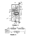
- the air conditioning duty cycling mechanism 91 shown in Fig. 5 and the control schematic shown in Fig. 6 includes a normally open switch 95 which is the same as switch 26 except as distinguished below.
- Switch 95 includes a thermally conductive hollow stem rivet 96 with a disc-like head 97.
- Position on stem 98 of rivet 96 is a bimetallic strip 99, including a ceramic post 101 and a non-conductive spacer 102.
- a first contact strip 103, including a contact point 104, is mounted on an annular boss 105 of spacer 102.
- a first terminal 106 rests on annular boss 105 above and in contact with the first contact strip 103.
- non-conductive spacer 107 positioned on rivet 96 through aperture 108 and nested on annular boss 105 through annular recess 109.
- a second contact strip 111 rests on an annular boss 112 of spacer 107.
- the second strip 111 includes a contact point 114 at one end thereof, and an overhanging portion 115 extending beyond the contact point 114 as well as a centrally located aperture 116.
- a second terminal 117 is also mounted on annular boss 112, in contact with the metal strip 111.
- Above terminal 117 is a non-conductive spacer 119 mounted to rivet 96 and nested on annular boss 112 at annular recess 122.
- a metal tab 123 is mounted on rivet 96 above spacer 109. These components are held tightly together by rivet 96 having an annular head 125.
- an adjusting means 12 comprising an internally threaded sleeve 127 and an externally threaded adjusting screw 128 within the sleeve.
- the upper end 129 of the adjusting screw has a slotted head.
- a non-conductive post 131 which is force- fit to the end of the adjustment screw and passes through the aperture 116 in contact strip 111 down to contact with first contact strip 103.
- the switch is adjusted by rotating the adjusting screw 128 which moves post 131 upwardly or downwardly relative to the contact strip 111 and alters the distance between strip 103 and strip 111, thereby altering the amount of movement required of the bimetal strip to permit points 104 and 114 to contact each other.
- the adjusting screw includes a radially extended member 133 and the sleeve 127 includes a raised portion 134 which lies in the path of rotation of radially extended member 133. These combine to limit the degree of rotation of the adjusting screw 128.
- the switch 95 is mounted to a metal housing 135 which is substantially the same as metal housing 21.
- the housing includes a top 136 and metal base plate 137 including a mounting flange 138 having apertures 139 to permit the passage of mounting screws 14-.
- the switch is held to the top of the housing by metal rivet 142 passing through the hollow stem 98 of rivet 96 and through spacer 140 which maintains switch 91 at a desired distance from top 136.
- the housing includes a rubber grommeted aperture 144 for wires 146 and 147 connected to terminals 106 and 117, respectively.
- this circuit is completed by a lead 15'2 going from the compressor to a transformer 153 and wire 154 from the transformer 153 to the thermostat making a complete circuit.
- the wire 147 from the switch 95 to the compressor and wire 152 from the compressor actually go to the activation switch of the compressor which activates the compressor upon receipt of electric current from the transformer via the thermostat.
- the switch 95 is closed, electrical current is received by the compressor from the thermostat causing the compressor to operate. Opening switch 95 simply breaks the circuit so that no electric current is received by the compressor to maintain the operation of the compressor.
- the bimetal switch for the air conditioner is designed to operate between 34°F and 150°F. Therefore, at normal room temperature, for example, about 70° or higher, the switch will be closed, i.e., the bimetal strip will be in a bent position. Again, the particular characteristics of the switch can be changed according to desire. However, these ranges of operation are believed to be the best mode currently known to the inventors. Switches such as these can be purchased which operate within desired ranges.
Landscapes
- Engineering & Computer Science (AREA)
- Chemical & Material Sciences (AREA)
- Combustion & Propulsion (AREA)
- Mechanical Engineering (AREA)
- General Engineering & Computer Science (AREA)
- Signal Processing (AREA)
- Physics & Mathematics (AREA)
- Fuzzy Systems (AREA)
- Mathematical Physics (AREA)
- Thermally Actuated Switches (AREA)
Applications Claiming Priority (2)
| Application Number | Priority Date | Filing Date | Title |
|---|---|---|---|
| US473573 | 1983-03-09 | ||
| US06/473,573 US4470267A (en) | 1983-03-09 | 1983-03-09 | Adjustable temperature sensitive duty cycling furnace and air conditioner control switch |
Publications (1)
| Publication Number | Publication Date |
|---|---|
| EP0119785A1 true EP0119785A1 (fr) | 1984-09-26 |
Family
ID=23880118
Family Applications (1)
| Application Number | Title | Priority Date | Filing Date |
|---|---|---|---|
| EP84301477A Withdrawn EP0119785A1 (fr) | 1983-03-09 | 1984-03-06 | Methode à commander la fonctionnement d un four et d un conditionner d air |
Country Status (3)
| Country | Link |
|---|---|
| US (1) | US4470267A (fr) |
| EP (1) | EP0119785A1 (fr) |
| CA (1) | CA1218729A (fr) |
Families Citing this family (5)
| Publication number | Priority date | Publication date | Assignee | Title |
|---|---|---|---|---|
| US4777929A (en) * | 1985-08-29 | 1988-10-18 | Temper-Sensor, Inc. | Mounting for duty cycle control switch for ceiling mounted ductless heater |
| US4664311A (en) * | 1985-08-29 | 1987-05-12 | Duty Cycle, Inc. | Mounting for duty cycle control switch for ceiling mounted ductless heater |
| US4712733A (en) * | 1986-03-24 | 1987-12-15 | Davis Raymond K | Internally mounted duty cycling control |
| US5226590A (en) * | 1992-01-15 | 1993-07-13 | Raymond K. Davis | Adaptor for mounting temperature sensitive duty cycling control with flexible duct work |
| US9282654B2 (en) | 2014-05-06 | 2016-03-08 | Honeywell International Inc. | HVAC controller with air flow barrier |
Citations (9)
| Publication number | Priority date | Publication date | Assignee | Title |
|---|---|---|---|---|
| US2267386A (en) * | 1940-07-05 | 1941-12-23 | Edison General Elec Appliance | Control device |
| US2314599A (en) * | 1940-07-27 | 1943-03-23 | William A Ray | Thermostat |
| US2716445A (en) * | 1951-04-02 | 1955-08-30 | Richard F Van Tubergen | Ignition and fuel supply control apparatus for fluid fuel pot-types burners |
| FR1293753A (fr) * | 1961-05-25 | 1962-05-18 | Dispositif de réglage électrique d'impulsions pour brûleurs à huile de fours céramiques | |
| GB1074565A (en) * | 1965-03-08 | 1967-07-05 | Honeywell Inc | Improvements in or relating to gas fired water heaters |
| US3845582A (en) * | 1972-03-03 | 1974-11-05 | Co Europ Pour L Equipment Mena | Control device for gas burner |
| US3921899A (en) * | 1974-07-19 | 1975-11-25 | Clair Hamilton | Electronic furnace control system |
| US4136730A (en) * | 1977-07-19 | 1979-01-30 | Kinsey Bernard B | Heating and cooling efficiency control |
| EP0107916A1 (fr) * | 1982-09-30 | 1984-05-09 | BBC Industries, INC. | Système de contrôle de flamme pour échangeur de chaleur |
Family Cites Families (3)
| Publication number | Priority date | Publication date | Assignee | Title |
|---|---|---|---|---|
| US3925680A (en) * | 1975-04-04 | 1975-12-09 | William A Dixon | Method and system for regulating peak residential power demand |
| US4141407A (en) * | 1975-07-21 | 1979-02-27 | Briscoe Harry H | Power demand limiting circuit |
| US4024411A (en) * | 1975-11-24 | 1977-05-17 | Bengoa Jose & 0 E | Apparatus for conserving electrical energy |
-
1983
- 1983-03-09 US US06/473,573 patent/US4470267A/en not_active Expired - Lifetime
-
1984
- 1984-02-28 CA CA000448469A patent/CA1218729A/fr not_active Expired
- 1984-03-06 EP EP84301477A patent/EP0119785A1/fr not_active Withdrawn
Patent Citations (9)
| Publication number | Priority date | Publication date | Assignee | Title |
|---|---|---|---|---|
| US2267386A (en) * | 1940-07-05 | 1941-12-23 | Edison General Elec Appliance | Control device |
| US2314599A (en) * | 1940-07-27 | 1943-03-23 | William A Ray | Thermostat |
| US2716445A (en) * | 1951-04-02 | 1955-08-30 | Richard F Van Tubergen | Ignition and fuel supply control apparatus for fluid fuel pot-types burners |
| FR1293753A (fr) * | 1961-05-25 | 1962-05-18 | Dispositif de réglage électrique d'impulsions pour brûleurs à huile de fours céramiques | |
| GB1074565A (en) * | 1965-03-08 | 1967-07-05 | Honeywell Inc | Improvements in or relating to gas fired water heaters |
| US3845582A (en) * | 1972-03-03 | 1974-11-05 | Co Europ Pour L Equipment Mena | Control device for gas burner |
| US3921899A (en) * | 1974-07-19 | 1975-11-25 | Clair Hamilton | Electronic furnace control system |
| US4136730A (en) * | 1977-07-19 | 1979-01-30 | Kinsey Bernard B | Heating and cooling efficiency control |
| EP0107916A1 (fr) * | 1982-09-30 | 1984-05-09 | BBC Industries, INC. | Système de contrôle de flamme pour échangeur de chaleur |
Also Published As
| Publication number | Publication date |
|---|---|
| CA1218729A (fr) | 1987-03-03 |
| US4470267A (en) | 1984-09-11 |
Similar Documents
| Publication | Publication Date | Title |
|---|---|---|
| US10281938B2 (en) | Method for a variable differential variable delay thermostat | |
| US5039006A (en) | Home heating system draft controller | |
| US4842044A (en) | Furnace control system | |
| US3948438A (en) | Thermostat system | |
| US4815524A (en) | Control system for a furnace operating in the continuous blower mode | |
| CA1314958C (fr) | Controle de l'utilisation d'energie dans un four | |
| US2704571A (en) | Safety control circuit for forced draft | |
| US4667874A (en) | Energy saving furnace controller | |
| JPS581262B2 (ja) | ジヨウタイ ニ オウジテ サヨウスル セイギヨソウチ | |
| US4140274A (en) | Control device for a warm air furnace | |
| US4485966A (en) | Pulsation device for a heating or cooling unit | |
| US5169301A (en) | Control system for gas fired heating apparatus using radiant heat sense | |
| US4470267A (en) | Adjustable temperature sensitive duty cycling furnace and air conditioner control switch | |
| US4147159A (en) | Temperature controlled instantaneous water heating apparatus | |
| US4355544A (en) | Control knob with rotation limiter | |
| US4089632A (en) | Fuel control safety apparatus | |
| US4175695A (en) | Fail-safe stack damper control system | |
| US4777929A (en) | Mounting for duty cycle control switch for ceiling mounted ductless heater | |
| US2786632A (en) | Control apparatus for forced air furnace | |
| US4712733A (en) | Internally mounted duty cycling control | |
| US4664311A (en) | Mounting for duty cycle control switch for ceiling mounted ductless heater | |
| US5226590A (en) | Adaptor for mounting temperature sensitive duty cycling control with flexible duct work | |
| USRE16444E (en) | Milton a | |
| US3494551A (en) | Furnace control system | |
| JP3506918B2 (ja) | ガス制御装置 |
Legal Events
| Date | Code | Title | Description |
|---|---|---|---|
| PUAI | Public reference made under article 153(3) epc to a published international application that has entered the european phase |
Free format text: ORIGINAL CODE: 0009012 |
|
| AK | Designated contracting states |
Designated state(s): AT BE CH DE FR GB IT LI LU NL SE |
|
| 17P | Request for examination filed |
Effective date: 19850201 |
|
| RAP1 | Party data changed (applicant data changed or rights of an application transferred) |
Owner name: DAVIS, RAYMOND KENNETH |
|
| RIN1 | Information on inventor provided before grant (corrected) |
Inventor name: BURNS, MARION CARL Inventor name: DAVIS, RAYMOND KENNETH |
|
| 17Q | First examination report despatched |
Effective date: 19861215 |
|
| STAA | Information on the status of an ep patent application or granted ep patent |
Free format text: STATUS: THE APPLICATION IS DEEMED TO BE WITHDRAWN |
|
| 18D | Application deemed to be withdrawn |
Effective date: 19900908 |
|
| RIN1 | Information on inventor provided before grant (corrected) |
Inventor name: DAVIS, RAYMOND KENNETH Inventor name: BURNS, MARION CARL |