EP0119848A2 - Anastomosekupplungsvorrichtung - Google Patents
Anastomosekupplungsvorrichtung Download PDFInfo
- Publication number
- EP0119848A2 EP0119848A2 EP84301797A EP84301797A EP0119848A2 EP 0119848 A2 EP0119848 A2 EP 0119848A2 EP 84301797 A EP84301797 A EP 84301797A EP 84301797 A EP84301797 A EP 84301797A EP 0119848 A2 EP0119848 A2 EP 0119848A2
- Authority
- EP
- European Patent Office
- Prior art keywords
- sleeve
- cuffs
- cuff
- tubular member
- inverted
- Prior art date
- Legal status (The legal status is an assumption and is not a legal conclusion. Google has not performed a legal analysis and makes no representation as to the accuracy of the status listed.)
- Withdrawn
Links
- 230000008878 coupling Effects 0.000 title claims abstract description 13
- 238000010168 coupling process Methods 0.000 title claims abstract description 13
- 238000005859 coupling reaction Methods 0.000 title claims abstract description 13
- 230000003872 anastomosis Effects 0.000 claims description 6
- 239000000463 material Substances 0.000 claims description 5
- 230000002496 gastric effect Effects 0.000 description 4
- 210000000056 organ Anatomy 0.000 description 4
- 230000006835 compression Effects 0.000 description 3
- 238000007906 compression Methods 0.000 description 3
- 230000035876 healing Effects 0.000 description 3
- 238000000034 method Methods 0.000 description 2
- RKDVKSZUMVYZHH-UHFFFAOYSA-N 1,4-dioxane-2,5-dione Chemical compound O=C1COC(=O)CO1 RKDVKSZUMVYZHH-UHFFFAOYSA-N 0.000 description 1
- AEMRFAOFKBGASW-UHFFFAOYSA-N Glycolic acid Polymers OCC(O)=O AEMRFAOFKBGASW-UHFFFAOYSA-N 0.000 description 1
- 239000004677 Nylon Substances 0.000 description 1
- 229920000954 Polyglycolide Polymers 0.000 description 1
- 239000004743 Polypropylene Substances 0.000 description 1
- 238000010521 absorption reaction Methods 0.000 description 1
- 230000006978 adaptation Effects 0.000 description 1
- 210000001367 artery Anatomy 0.000 description 1
- 229920001577 copolymer Polymers 0.000 description 1
- 210000001035 gastrointestinal tract Anatomy 0.000 description 1
- 208000015181 infectious disease Diseases 0.000 description 1
- 210000000936 intestine Anatomy 0.000 description 1
- JJTUDXZGHPGLLC-UHFFFAOYSA-N lactide Chemical compound CC1OC(=O)C(C)OC1=O JJTUDXZGHPGLLC-UHFFFAOYSA-N 0.000 description 1
- 230000001926 lymphatic effect Effects 0.000 description 1
- 238000003754 machining Methods 0.000 description 1
- 238000000465 moulding Methods 0.000 description 1
- 229920001778 nylon Polymers 0.000 description 1
- 229920000747 poly(lactic acid) Polymers 0.000 description 1
- 229920002463 poly(p-dioxanone) polymer Polymers 0.000 description 1
- 239000000622 polydioxanone Substances 0.000 description 1
- -1 polypropylene Polymers 0.000 description 1
- 229920001155 polypropylene Polymers 0.000 description 1
- 229910001220 stainless steel Inorganic materials 0.000 description 1
- 239000010935 stainless steel Substances 0.000 description 1
- 239000003356 suture material Substances 0.000 description 1
- 210000003462 vein Anatomy 0.000 description 1
Images
Classifications
-
- A—HUMAN NECESSITIES
- A61—MEDICAL OR VETERINARY SCIENCE; HYGIENE
- A61B—DIAGNOSIS; SURGERY; IDENTIFICATION
- A61B17/00—Surgical instruments, devices or methods
- A61B17/11—Surgical instruments, devices or methods for performing anastomosis; Buttons for anastomosis
- A61B17/1114—Surgical instruments, devices or methods for performing anastomosis; Buttons for anastomosis of the digestive tract, e.g. bowels or oesophagus
-
- A—HUMAN NECESSITIES
- A61—MEDICAL OR VETERINARY SCIENCE; HYGIENE
- A61B—DIAGNOSIS; SURGERY; IDENTIFICATION
- A61B17/00—Surgical instruments, devices or methods
- A61B2017/00004—(bio)absorbable, (bio)resorbable or resorptive
-
- A—HUMAN NECESSITIES
- A61—MEDICAL OR VETERINARY SCIENCE; HYGIENE
- A61F—FILTERS IMPLANTABLE INTO BLOOD VESSELS; PROSTHESES; DEVICES PROVIDING PATENCY TO, OR PREVENTING COLLAPSING OF, TUBULAR STRUCTURES OF THE BODY, e.g. STENTS; ORTHOPAEDIC, NURSING OR CONTRACEPTIVE DEVICES; FOMENTATION; TREATMENT OR PROTECTION OF EYES OR EARS; BANDAGES, DRESSINGS OR ABSORBENT PADS; FIRST-AID KITS
- A61F2/00—Filters implantable into blood vessels; Prostheses, i.e. artificial substitutes or replacements for parts of the body; Appliances for connecting them with the body; Devices providing patency to, or preventing collapsing of, tubular structures of the body, e.g. stents
- A61F2/02—Prostheses implantable into the body
- A61F2/30—Joints
- A61F2002/30001—Additional features of subject-matter classified in A61F2/28, A61F2/30 and subgroups thereof
- A61F2002/30316—The prosthesis having different structural features at different locations within the same prosthesis; Connections between prosthetic parts; Special structural features of bone or joint prostheses not otherwise provided for
- A61F2002/30329—Connections or couplings between prosthetic parts, e.g. between modular parts; Connecting elements
- A61F2002/30476—Connections or couplings between prosthetic parts, e.g. between modular parts; Connecting elements locked by an additional locking mechanism
- A61F2002/305—Snap connection
-
- A—HUMAN NECESSITIES
- A61—MEDICAL OR VETERINARY SCIENCE; HYGIENE
- A61F—FILTERS IMPLANTABLE INTO BLOOD VESSELS; PROSTHESES; DEVICES PROVIDING PATENCY TO, OR PREVENTING COLLAPSING OF, TUBULAR STRUCTURES OF THE BODY, e.g. STENTS; ORTHOPAEDIC, NURSING OR CONTRACEPTIVE DEVICES; FOMENTATION; TREATMENT OR PROTECTION OF EYES OR EARS; BANDAGES, DRESSINGS OR ABSORBENT PADS; FIRST-AID KITS
- A61F2220/00—Fixations or connections for prostheses classified in groups A61F2/00 - A61F2/26 or A61F2/82 or A61F9/00 or A61F11/00 or subgroups thereof
- A61F2220/0025—Connections or couplings between prosthetic parts, e.g. between modular parts; Connecting elements
-
- A—HUMAN NECESSITIES
- A61—MEDICAL OR VETERINARY SCIENCE; HYGIENE
- A61F—FILTERS IMPLANTABLE INTO BLOOD VESSELS; PROSTHESES; DEVICES PROVIDING PATENCY TO, OR PREVENTING COLLAPSING OF, TUBULAR STRUCTURES OF THE BODY, e.g. STENTS; ORTHOPAEDIC, NURSING OR CONTRACEPTIVE DEVICES; FOMENTATION; TREATMENT OR PROTECTION OF EYES OR EARS; BANDAGES, DRESSINGS OR ABSORBENT PADS; FIRST-AID KITS
- A61F2310/00—Prostheses classified in A61F2/28 or A61F2/30 - A61F2/44 being constructed from or coated with a particular material
- A61F2310/00005—The prosthesis being constructed from a particular material
- A61F2310/00011—Metals or alloys
- A61F2310/00017—Iron- or Fe-based alloys, e.g. stainless steel
Definitions
- the present-invention relates to devices for end-to-end anastomosis of tubular organs and, more particularly, to an anastomotic coupling device for reconnecting the ends of severed gastro-intestinal tract in a manner to promote the healing thereof.
- End-to-end anastomosis of the gastric organs may be accon- plished by suturing, stapling, or mechanical coupling.
- Suturing is generally tedious to perform and requires great skill and experience on the part of the surgeon.
- Suturing is also susceptible to complications resulting from damage to the gastric wall, leakage, potential harboring of infection around the suture material, and the like.
- The-ideal anastonotic coupling device should provide perfect adaptation of the tubular members without damage to the gastric wall.
- the device should provide for quick, sure placement with a minimal possibility for error on the part of the surgeon. It is preferred the device be simple and economical to produce. In many instances, it is desirable that the anastomotic device be completely internal of the gastric lumen. There are other instances where it is desirable that the anastomotic device be substantially contained outside the lumen.
- an object of the present invention to provide an anastomotic device particularly adapted to joining gastro-intestional organs.
- a further object of this invention is to provide a device for joining the ends of interrupted tubular organs of various sizes and functions including, for example, intestines, veins, arteries, lymphatic ducts, ova ducts, and the like.
- the anastomotic coupling device of the present invention consists of three pieces: two tubular cuffs and one locking sleeve.
- Preferred cuffs consist of a cylinder having an axial bore therein with smooth inner and outer surfaces. It is preferred one end of the cuffs have a shoulder which is used to abut a portion of the sleeve and lock the device in its final configuration in use.
- the cuffs are sized to fit within the lumen of a tubular member; that is, the tubular member to be joined. The tubular member is inverted over the end of the cuff opposite the end having the shoulder.
- the sleeve is cylindrical in configuration and has an axial bore therethrough and is sized to fit within the axial bore of the cuffs.
- the sleeve has means disposed at each end of the sleeve to lock with the cuff in the final device configuration such as an undercut ledge that engages the shoulder at one end of the cuff.
- the outer surface of the cylindrical member is serrated or has circular grooves on it to aid in holding the tubular member in place.
- one end of the tubular member to be joined is passed over the outer surface of a cuff and the tubular member is inverted so that the end fits inside the cuff.
- the cuff is then placed on one side of the sleeve so that the shoulder abuts against a ledge at the end of the sleeve.
- the other portion of the tubular member to be joined is placed over the second cuff and inverted so that the end of the tubular member fits inside the cuff.
- the second cuff with the tubular member inverted thereover is then sliped on the other end of the sleeve and locked in place by an appropriate undercut ledge so that the tubular members abut each other and are locked in place.
- the inside diameter of the cuffs is greater than the outside diameter of the sleeve by a sufficient amount to accommodate the wall thickness of the inverted tubular member.
- the diameters are preferably sized so that a small compressive force is inserted on the wall of the joined tubular member in the ,assernbled connector.
- the outer wall of the sleeve may contain serrations or otherwise be abraded to aid in holding the tubular member in place.
- the length of the sleeve and the pair of cuffs are such that when assembled the ends of the cuffs which face each other are spaced apart by a distance slightly less than twice the wall thickness of the tubular member being joined. In this manner the surfaces of the inverted ends of the tubular members are brought into contact under light compression which is effectfve to prevent leakage and is also desirable to promote healing of the joined tissue.
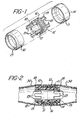
- Figure 1 is an exploded view in perspective showing the three pieces of the new anastomotic coupler of the present invention.
- Figure 2 is a cross-sectional view showing the new anastomotic coupler of the present invention joining a tubular vessel together.
- FIG. 1 there is shown a pair of cuffs 10 and 11 and a sleeve 12.
- the cuffs are identical and are generally cylindrical having a smooth innersurface and a smooth outer surface.
- an offset or shoulder portion 13 and 14 at one end of each cuff.
- This shoulder portion is formed by tapering the cuff from its outer surface to its inner surface at this end.
- the sleeve is also cylindrical in nature and the embodiment depicted has four legs 15 depending from each side of central portion 16 of the sleeve. Though in this embodiment the cylinder is discontinuous at each end to form four legs, the cylinder could form any number of legs or in fact be continuous or form only a single leg at each end.
- the central portion 16 of the sleeve has a plurality of circular grooves 17 or serrations about its periphery.
- the tubular member 30 to be joined is passed over the outside surface of a cuff and inverted down into the inside surface of the cuff.
- the sleeve is then passed down into the inside surface of the cuff so the ledge 18 on at least two of the legs engage the shoulder 13 of the cuff.
- the other end of the tubular member to be joined has the second cuff 11 inserted within its lumen and the tubular member inverted over the edge of the cuff.
- the cuff with the tubular member inverted over its end is placed on the opposite end of the sleeve 12 so that the ledge 19 on at least two of the legs at the opposite end of the sleeve engage the shoulder 14 of the cuff 11 to lock the device together and join the tubular members.
- the outside diameter of the cuffs should be the same size or slightly smaller than the inside diameter of the tubular member to be joined.
- the spacing between the cuffs should be slightly less than twice the thickness of the tubular member being joined so that as is seen in Figure 2 slight compression is placed on the tissue in the area where they are abutted. This slight compression establishes hemostatis and aids in the joining and healing of the tissue.
- the new coupling devices of the present invention may be manufactured by any convenient technique such as machining or molding.
- the device may be made from a variety of materials which are known to be bio-compatible in surgical applications. Nylon, polypropylene, and polysulfonate are illustrative of polymeric materials which are readily shaped into the minature pieces of the coupling device.
- the device may also be fabricated of stainless steel or of biologically absorbable materials such as polylactide, polyglycolide, polydioxanone, copolymers of lactide and glycolide, etc., which are known to hydrolyze in tissue with eventual complete absorption by the body.
- the essential element of the invention is a three-piece coupling device for end-to-end anastomosis of tubular members.
Landscapes
- Health & Medical Sciences (AREA)
- Surgery (AREA)
- Life Sciences & Earth Sciences (AREA)
- Biomedical Technology (AREA)
- Nuclear Medicine, Radiotherapy & Molecular Imaging (AREA)
- Engineering & Computer Science (AREA)
- Physiology (AREA)
- Heart & Thoracic Surgery (AREA)
- Medical Informatics (AREA)
- Molecular Biology (AREA)
- Animal Behavior & Ethology (AREA)
- General Health & Medical Sciences (AREA)
- Public Health (AREA)
- Veterinary Medicine (AREA)
- Surgical Instruments (AREA)
Applications Claiming Priority (2)
| Application Number | Priority Date | Filing Date | Title |
|---|---|---|---|
| US47630383A | 1983-03-17 | 1983-03-17 | |
| US476303 | 1995-06-07 |
Publications (2)
| Publication Number | Publication Date |
|---|---|
| EP0119848A2 true EP0119848A2 (de) | 1984-09-26 |
| EP0119848A3 EP0119848A3 (de) | 1986-02-26 |
Family
ID=23891313
Family Applications (1)
| Application Number | Title | Priority Date | Filing Date |
|---|---|---|---|
| EP84301797A Withdrawn EP0119848A3 (de) | 1983-03-17 | 1984-03-16 | Anastomosekupplungsvorrichtung |
Country Status (4)
| Country | Link |
|---|---|
| EP (1) | EP0119848A3 (de) |
| JP (1) | JPS59177039A (de) |
| AR (1) | AR230938A1 (de) |
| CA (1) | CA1243246A (de) |
Cited By (13)
| Publication number | Priority date | Publication date | Assignee | Title |
|---|---|---|---|---|
| EP0199074A1 (de) * | 1985-03-25 | 1986-10-29 | American Cyanamid Company | Verfahren zur herstellung einer wärmebehandelten prothetischen Vorrichtung |
| US4625727A (en) * | 1985-01-24 | 1986-12-02 | Leiboff Arnold R | Anastomosis device with excisable frame |
| EP0326757A1 (de) * | 1988-02-05 | 1989-08-09 | Tatsuo Fujitsuka | Vorrichtung zur Anastomose des Verdauungssystems |
| US4899744A (en) * | 1988-12-15 | 1990-02-13 | Tatsuo Fujitsuka | Apparatus for anastomosing digestive tract |
| EP0362163A3 (de) * | 1988-09-28 | 1991-07-17 | Carlo Rebuffat | Kompressionsgerät für die Anastomose von hohlen Organen |
| US5180392A (en) * | 1988-02-01 | 1993-01-19 | Einar Skeie | Anastomotic device |
| WO2007122223A1 (en) * | 2006-04-21 | 2007-11-01 | Carponovum Ab | A device and a method for anastomosis |
| EP1908419A1 (de) * | 2006-10-06 | 2008-04-09 | Ethicon Endo-Surgery, Inc. | Verriegelungsvorrichtung für eine Anastomosevorrichtung |
| EP1802237A4 (de) * | 2004-10-18 | 2010-06-30 | Tyco Healthcare | Vorrichtung und verfahren für kompressionsanastomose |
| KR101397170B1 (ko) * | 2006-04-21 | 2014-05-19 | 카포노붐 에이비 | 마운팅 도구 |
| WO2018101832A1 (en) | 2016-12-02 | 2018-06-07 | Implican B.V. | Instrument for performing anastomosis |
| CN117064474A (zh) * | 2023-10-17 | 2023-11-17 | 山东百多安医疗器械股份有限公司 | 一种可降解血管吻合装置 |
| CN119326465A (zh) * | 2024-12-24 | 2025-01-21 | 四川大学华西医院 | 一种用于双侧方开口的胃肠、肠肠或胆肠吻合器械 |
Families Citing this family (3)
| Publication number | Priority date | Publication date | Assignee | Title |
|---|---|---|---|---|
| JPS62152446A (ja) * | 1985-12-24 | 1987-07-07 | 株式会社日本メデイカル・サプライ | 血管吻合のための器具 |
| JP4504599B2 (ja) * | 2001-07-27 | 2010-07-14 | 治文 加藤 | 吻合用補助具 |
| CN113143372A (zh) * | 2021-05-20 | 2021-07-23 | 上海理工大学 | 一种可降解的加压式管腔组织吻合支架 |
Family Cites Families (6)
| Publication number | Priority date | Publication date | Assignee | Title |
|---|---|---|---|---|
| US3683926A (en) * | 1970-07-09 | 1972-08-15 | Dainippon Pharmaceutical Co | Tube for connecting blood vessels |
| US3974835A (en) * | 1972-11-30 | 1976-08-17 | Hardy Jr Thomas G | Anastomotic apparatus and method |
| US4214586A (en) * | 1978-11-30 | 1980-07-29 | Ethicon, Inc. | Anastomotic coupling device |
| JPS5642939A (en) * | 1979-09-17 | 1981-04-21 | Hitachi Ltd | Method for forming fluorescent surface on cathode-ray tube |
| ZA817222B (en) * | 1980-10-20 | 1982-09-29 | American Cyanamid Co | Anastomotic device and method |
| US4467804A (en) * | 1980-10-20 | 1984-08-28 | American Cyanamid Company | Anastomotic device |
-
1984
- 1984-03-12 CA CA000449357A patent/CA1243246A/en not_active Expired
- 1984-03-13 JP JP4663384A patent/JPS59177039A/ja active Pending
- 1984-03-16 EP EP84301797A patent/EP0119848A3/de not_active Withdrawn
- 1984-03-17 AR AR29602484A patent/AR230938A1/es active
Cited By (24)
| Publication number | Priority date | Publication date | Assignee | Title |
|---|---|---|---|---|
| US4625727A (en) * | 1985-01-24 | 1986-12-02 | Leiboff Arnold R | Anastomosis device with excisable frame |
| EP0199074A1 (de) * | 1985-03-25 | 1986-10-29 | American Cyanamid Company | Verfahren zur herstellung einer wärmebehandelten prothetischen Vorrichtung |
| US5180392A (en) * | 1988-02-01 | 1993-01-19 | Einar Skeie | Anastomotic device |
| EP0326757A1 (de) * | 1988-02-05 | 1989-08-09 | Tatsuo Fujitsuka | Vorrichtung zur Anastomose des Verdauungssystems |
| EP0362163A3 (de) * | 1988-09-28 | 1991-07-17 | Carlo Rebuffat | Kompressionsgerät für die Anastomose von hohlen Organen |
| US4899744A (en) * | 1988-12-15 | 1990-02-13 | Tatsuo Fujitsuka | Apparatus for anastomosing digestive tract |
| AU2005296053B2 (en) * | 2004-10-18 | 2011-03-10 | Covidien Lp | Compression anastomosis device and method |
| US9023068B2 (en) | 2004-10-18 | 2015-05-05 | Covidien Lp | Compression anastomosis device and method |
| US8109948B2 (en) | 2004-10-18 | 2012-02-07 | Tyco Healthcare Group Lp | Compression anastomosis device and method |
| EP1802237A4 (de) * | 2004-10-18 | 2010-06-30 | Tyco Healthcare | Vorrichtung und verfahren für kompressionsanastomose |
| WO2007122223A1 (en) * | 2006-04-21 | 2007-11-01 | Carponovum Ab | A device and a method for anastomosis |
| US9155539B2 (en) | 2006-04-21 | 2015-10-13 | Carponovum Ab | Mounting tool and a method for a device for anastomosis |
| NO343928B1 (no) * | 2006-04-21 | 2019-07-08 | Carponovum Ab | Anordning og fremgangsmåte for anastomose |
| US8512361B2 (en) | 2006-04-21 | 2013-08-20 | Carponovum Ab | Device and a method for anastomosis |
| KR101351492B1 (ko) * | 2006-04-21 | 2014-01-14 | 카포노붐 에이비 | 문합기구 |
| KR101397170B1 (ko) * | 2006-04-21 | 2014-05-19 | 카포노붐 에이비 | 마운팅 도구 |
| CN101426430B (zh) * | 2006-04-21 | 2011-11-02 | 卡波诺凡公司 | 用于吻合术的器械 |
| EP1908419A1 (de) * | 2006-10-06 | 2008-04-09 | Ethicon Endo-Surgery, Inc. | Verriegelungsvorrichtung für eine Anastomosevorrichtung |
| WO2008040577A1 (en) * | 2006-10-06 | 2008-04-10 | Ethicon Endo-Surgery, Inc. | A locking device for an anastomotic device |
| WO2018101832A1 (en) | 2016-12-02 | 2018-06-07 | Implican B.V. | Instrument for performing anastomosis |
| EP3547935B1 (de) | 2016-12-02 | 2025-07-16 | Implican B.V. | Instrument zur durchführung einer anastomose |
| CN117064474A (zh) * | 2023-10-17 | 2023-11-17 | 山东百多安医疗器械股份有限公司 | 一种可降解血管吻合装置 |
| CN117064474B (zh) * | 2023-10-17 | 2024-01-05 | 山东百多安医疗器械股份有限公司 | 一种可降解血管吻合装置 |
| CN119326465A (zh) * | 2024-12-24 | 2025-01-21 | 四川大学华西医院 | 一种用于双侧方开口的胃肠、肠肠或胆肠吻合器械 |
Also Published As
| Publication number | Publication date |
|---|---|
| EP0119848A3 (de) | 1986-02-26 |
| JPS59177039A (ja) | 1984-10-06 |
| CA1243246A (en) | 1988-10-18 |
| AR230938A1 (es) | 1984-08-31 |
Similar Documents
| Publication | Publication Date | Title |
|---|---|---|
| CA1135456A (en) | Anastomotic coupling device | |
| EP0119848A2 (de) | Anastomosekupplungsvorrichtung | |
| US4534350A (en) | Two-piece tissue fastener with compressible leg staple and retaining receiver | |
| AU2005296053B2 (en) | Compression anastomosis device and method | |
| EP0070923B1 (de) | Vorrichtung und Verfahren zum Anastomosieren | |
| US4873976A (en) | Surgical fasteners and method | |
| US4693248A (en) | Two-piece tissue fastener with deformable retaining receiver | |
| US4532927A (en) | Two-piece tissue fastener with non-reentry bent leg staple and retaining receiver | |
| JPH0569540B2 (de) | ||
| US4724839A (en) | Surgical fastening systems made from polymeric materials | |
| US4693249A (en) | Anastomosis device and method | |
| US5346501A (en) | Laparoscopic absorbable anastomosic fastener and means for applying | |
| CN1023374C (zh) | 吻合装置 | |
| CA2568874C (en) | Compression anastomosis device | |
| US4602634A (en) | Method and instrument for applying a fastener to a tissue using means to grasp, guide and pull the fastener through the tissue | |
| EP0326757B1 (de) | Vorrichtung zur Anastomose des Verdauungssystems |
Legal Events
| Date | Code | Title | Description |
|---|---|---|---|
| PUAI | Public reference made under article 153(3) epc to a published international application that has entered the european phase |
Free format text: ORIGINAL CODE: 0009012 |
|
| AK | Designated contracting states |
Designated state(s): DE GB |
|
| PUAL | Search report despatched |
Free format text: ORIGINAL CODE: 0009013 |
|
| AK | Designated contracting states |
Designated state(s): DE GB |
|
| STAA | Information on the status of an ep patent application or granted ep patent |
Free format text: STATUS: THE APPLICATION IS DEEMED TO BE WITHDRAWN |
|
| 18D | Application deemed to be withdrawn |
Effective date: 19870129 |
|
| RIN1 | Information on inventor provided before grant (corrected) |
Inventor name: MERICLE, ROBERT WILLIAM |