EP0119909A1 - Four à longerons réfractaires - Google Patents
Four à longerons réfractaires Download PDFInfo
- Publication number
- EP0119909A1 EP0119909A1 EP84400468A EP84400468A EP0119909A1 EP 0119909 A1 EP0119909 A1 EP 0119909A1 EP 84400468 A EP84400468 A EP 84400468A EP 84400468 A EP84400468 A EP 84400468A EP 0119909 A1 EP0119909 A1 EP 0119909A1
- Authority
- EP
- European Patent Office
- Prior art keywords
- products
- oven
- beams
- recesses
- refractory
- Prior art date
- Legal status (The legal status is an assumption and is not a legal conclusion. Google has not performed a legal analysis and makes no representation as to the accuracy of the status listed.)
- Granted
Links
- 239000003517 fume Substances 0.000 claims abstract description 10
- 238000010438 heat treatment Methods 0.000 claims abstract description 6
- 239000000779 smoke Substances 0.000 claims abstract description 3
- 239000002184 metal Substances 0.000 claims description 5
- 230000003247 decreasing effect Effects 0.000 claims description 2
- 238000005452 bending Methods 0.000 description 5
- 239000000567 combustion gas Substances 0.000 description 3
- 230000007423 decrease Effects 0.000 description 2
- 206010022000 influenza Diseases 0.000 description 2
- 235000000396 iron Nutrition 0.000 description 2
- 230000005855 radiation Effects 0.000 description 2
- UGFAIRIUMAVXCW-UHFFFAOYSA-N Carbon monoxide Chemical compound [O+]#[C-] UGFAIRIUMAVXCW-UHFFFAOYSA-N 0.000 description 1
- 238000002485 combustion reaction Methods 0.000 description 1
- 230000001627 detrimental effect Effects 0.000 description 1
- 239000000428 dust Substances 0.000 description 1
- 230000008030 elimination Effects 0.000 description 1
- 238000003379 elimination reaction Methods 0.000 description 1
- 239000003546 flue gas Substances 0.000 description 1
- 239000011819 refractory material Substances 0.000 description 1
- 238000003303 reheating Methods 0.000 description 1
- 230000000284 resting effect Effects 0.000 description 1
- 238000005096 rolling process Methods 0.000 description 1
- XLYOFNOQVPJJNP-UHFFFAOYSA-N water Substances O XLYOFNOQVPJJNP-UHFFFAOYSA-N 0.000 description 1
Images

Classifications
-
- F—MECHANICAL ENGINEERING; LIGHTING; HEATING; WEAPONS; BLASTING
- F27—FURNACES; KILNS; OVENS; RETORTS
- F27B—FURNACES, KILNS, OVENS OR RETORTS IN GENERAL; OPEN SINTERING OR LIKE APPARATUS
- F27B9/00—Furnaces through which the charge is moved mechanically, e.g. of tunnel type; Similar furnaces in which the charge moves by gravity
- F27B9/30—Details, accessories or equipment specially adapted for furnaces of these types
- F27B9/3005—Details, accessories or equipment specially adapted for furnaces of these types arrangements for circulating gases
- F27B9/3011—Details, accessories or equipment specially adapted for furnaces of these types arrangements for circulating gases arrangements for circulating gases transversally
-
- F—MECHANICAL ENGINEERING; LIGHTING; HEATING; WEAPONS; BLASTING
- F27—FURNACES; KILNS; OVENS; RETORTS
- F27B—FURNACES, KILNS, OVENS OR RETORTS IN GENERAL; OPEN SINTERING OR LIKE APPARATUS
- F27B9/00—Furnaces through which the charge is moved mechanically, e.g. of tunnel type; Similar furnaces in which the charge moves by gravity
- F27B9/14—Furnaces through which the charge is moved mechanically, e.g. of tunnel type; Similar furnaces in which the charge moves by gravity characterised by the path of the charge during treatment; characterised by the means by which the charge is moved during treatment
- F27B9/20—Furnaces through which the charge is moved mechanically, e.g. of tunnel type; Similar furnaces in which the charge moves by gravity characterised by the path of the charge during treatment; characterised by the means by which the charge is moved during treatment the charge moving in a substantially straight path
- F27B9/201—Furnaces through which the charge is moved mechanically, e.g. of tunnel type; Similar furnaces in which the charge moves by gravity characterised by the path of the charge during treatment; characterised by the means by which the charge is moved during treatment the charge moving in a substantially straight path walking beam furnace
- F27B9/202—Conveyor mechanisms therefor
- F27B9/203—Conveyor mechanisms therefor having ramps
-
- F—MECHANICAL ENGINEERING; LIGHTING; HEATING; WEAPONS; BLASTING
- F27—FURNACES; KILNS; OVENS; RETORTS
- F27D—DETAILS OR ACCESSORIES OF FURNACES, KILNS, OVENS OR RETORTS, IN SO FAR AS THEY ARE OF KINDS OCCURRING IN MORE THAN ONE KIND OF FURNACE
- F27D3/00—Charging; Discharging; Manipulation of charge
- F27D3/02—Skids or tracks for heavy objects
- F27D3/022—Skids
- F27D3/024—Details of skids, e.g. riders
Definitions
- Ovens intended for continuous heating, before rolling of products such as billets or blooms are often with mobile beams.
- a part of the sole is formed of fixed beams while the remaining part consists of mobile beams and has a circular or rectangular movement.
- the products rest alternately on the fixed beams and on the mobile beams whose movement ensures the progression of these products.
- the beams of these ovens can be hollow and cooled by water circulation. They can also be made of refractory material, which reduces the thermal consumption of the furnace, given the elimination of thermal losses from the cooled elements.
- the products are heated mainly by the radiation from the furnace on their upper face and on their lateral faces.
- Their lower face which is constantly in contact with the refractory hearth, is heated only by the thermal conduction coming from the other faces and, in most of the oven, is at a temperature lower than that of the rest of the product.
- This temperature difference causes a difference in expansion of the upper and lower faces of the product, which leads to bending of the latter in the vertical plane. This bending is detrimental to the progression of the products on the floor; in fact, the bent products tend to tip over and then risk overlapping if the deflection of the bending is greater than the interval which separates two successive products.
- U.S. Patent 1,400,367 describes an oven comprising a hearth provided with slots in which are engaged movable beams separated by a fixed beam of width greater than that of the movable beams.
- the side walls of the slots open flues bringing the combustion gases; these circulate around the movable elements of the floor and prevent cold air from entering through the slits.
- the combustion gases and the fumes exiting through slits which have a limited width cannot heat the underside of the products, therefore preventing their bending.
- the side walls of the slits and. those of the moving beams are in contact with the fumes and dust they contain; this is a drawback given the relative movement of the walls of the slots and those of the side members.
- the present invention relates to an oven with refractory beams, with higher heating, which on the contrary makes it possible to avoid practically any bending of the products.
- This oven in which the fixed beams of the hearth have a width greater than that of the mobile beams and have recesses connected to the general flue gas circuit, is characterized in that the recesses open onto the upper face of the beams so that the fumes pass through the bed of products surmounting them.
- the fumes pass through the bed of products and heat the underside of the products, which thus expands practically like their upper side.
- the recesses preferably have a decreasing depth in the direction of movement of the products. They thus have an increasing passage section with the direction of flow of the fumes, which compensates for their drop in temperature.
- the recesses can have different depths, the depth of a recess being a function of its position relative to the longitudinal median plane of the furnace. This gives flow rates smoke under the products, therefore reheating the underside of these products, which depend on the place of said products relative to the axis of the oven. It is thus possible to compensate for an asymmetry in the heating of the oven.
- the fixed beams may include longitudinal metal profiles suitable for supporting the products and themselves supported by the lower frame of the oven.
- the oven has a roof 1, side walls such as 2 and a front wall 3 and has a longitudinal median plane A-A. Its sole is formed of refractory fixed beams 4 separated by mobile refractory beams 5 whose width is less than that of the fixed beams. Burners, not shown, make it possible to circulate combustion gases against the current in the upper zone of the furnace, above the longitudinal members 4 and 5.
- the fixed beams 4 are supported by metal profiles 6 called “sole irons” forming an integral part of the metal frame of the oven which is generally designated in the drawing by the reference 7.
- the mobile beams 5 are on their side supported by crosspieces 8, which, together with the side members 9, constitute a movable frame.
- This chassis is supported, by means of uprights 10, by a chassis 11 which rests on a chassis 12 by means of rollers 13 and that a system of jacks, not shown, makes it possible to move longitudinally.
- the chassis 12 rests itself, by means of rollers 14 on fixed inclined planes 15 and can be moved longitudinally by a system of jacks also not shown.
- the movable beams 5 are moved both longitudinally and vertically, while if the chassis 11 is moved, the movable beams 5 only move longitudinally.
- the fixed rails 4 have recesses such as 17a and 17b whose depth decreases in the direction of progression of the products, that is to say in the direction of the arrow F in Figure 2.
- the greatest depth of these recesses is therefore at the level of the oven.
- the recess-17a located near the longitudinal median plane A-A has a shallower depth than the recess 17b.
- the various recesses are connected to a manifold 18 by flues such as 19 which are supported by a frame 20 integral with the oven.
- the fumes resulting from the combustion pass through the recesses 17a and 17b, therefore the bed of products to which they give up by convection part of their sensible heat. Then flowing under the bed, in the recesses, they radiate on the undersides of the products which are thus heated.
- the lower face of the products 16 is brought to practically the same temperature as their upper face and expands substantially by the same value.
- the product hanger is eliminated or at least considerably reduced.
Landscapes
- Engineering & Computer Science (AREA)
- Mechanical Engineering (AREA)
- General Engineering & Computer Science (AREA)
- Heat Treatments In General, Especially Conveying And Cooling (AREA)
- Tunnel Furnaces (AREA)
Abstract
Description
- Les fours destinés au chauffage en continu, avant laminage de produits tels que des billettes ou des blooms sont souvent à longerons mobiles. Une partie de la sole est formée de longerons fixes alors que la partie restante est constituée de longerons mobiles et a un mouvement circulaire ou rectangulaire. Les produits reposent alternativement sur les longerons fixes et sur les longerons mobiles dont le mouvement assure la progression de ces produits.
- Les longerons de ces fours peuvent être creux et refroidis par circulation d'eau. Ils peuvent également être en matière réfractaire, ce qui diminue la consommation thermique du four, étant donné la suppression des pertes thermiques des éléments refroidis.
- Dans les fours à longerons réfractaires le chauffage des produits est assuré principalement par le rayonnement du four sur leur face supérieure et sur leurs faces latérales. Leur face inférieure qui est constamment en contact avec la sole réfractaire, n'est chauffée que par la conduction thermique provenant des autres faces et, dans la plus grande partie du four, se trouve à une température inférieure à celle du reste du produit.
- Cette différence de température provoque une différence de dilatation des faces supérieure et inférieure du produit, ce qui enf traîne un cintrage de celui-ci dans le plan vertical. Ce cintrage est préjudiciable à la progression des produits sur la sole; en effet, les produits cintrés ont tendance à basculer et risquent alors de se chevaucher si la flèche du cintrage est supérieure à l'intervalle qui sépare deux produits successifs.
- Le brevet U.S. 1,400,367 décrit un four comportant une sole munie de fentes dans lesquelles sont engagés des longerons mobiles séparés par un longeron fixe de largeur supérieure à celle des longerons mobiles. Dans les parois latérales des fentes débouchent des carneaux amenant les gaz de combustion; ceux-ci circulent autour des éléments mobiles de la sole et évitent les rentrées d'air froid par les fentes. Mais les gaz de combustion et les fumées sortant par des fentes qui ont une largeur limitée ne peuvent chauffer la face inférieure des produits, donc éviter leur cintrage.De plus , les parois latérales des fentes et. celles des longerons mobiles sont au contact des fumées et des poussières qu'elles contiennent; cela est un inconvénient étant donné le mouvement relatif des parois des fentes et de celles des longerons.
- La présente invention a pour objet un four à longerons réfractaires, à chauffage supérieur, qui permet au contraire d'éviter pratiquement tout cintrage des produits.
- Ce four dans lequel les longerons fixes de la sole ont une largeur supérieure à celle des longerons mobiles et comportent des évidements reliés au circuit général des fumées, est caractérisé en ce que les évidements débouchent sur la face supérieure des longerons de sorte que les fumées traversent le lit de produits les surmontant.
- Lors de l'utilisation du four, les fumées traversent le lit de produits et assurent le chauffage de la face inférieure des produits, qui se dilate ainsi pratiquement comme leur face supérieure.
- Les évidements ont, de préférence, une profondeur décroissant dans le sens de déplacement des produits. Ils présentent ainsi une section de passage croissant avec le sens d'écoulement des fumées, ce qui compense leur baisse de température.
- Les évidements peuvent avoir des profondeurs différentes, la profondeur d'un évidement étant fonction de sa position par rapport au plan médian longitudinal du four. On obtient ainsi des débits de fumées sous les produits, donc un réchauffage de la face inférieure de ces produits, qui dépendent de la place desdits produits par rapport à l'axe du four. Il est ainsi possible de compenser une dissymétrie de chauffage du four.
- Les longerons fixes peuvent comporter des profilés métalliques longitudinaux propres à supporter les produits et supportés eux-mêmes par l'armature inférieure du four.
- On a décrit ci-après, à titre d'exemple non limitatif, un mode de réalisation d'un four à longerons réfractaires perfectionné selon la présente invention, avec référence au dessin annexé dans lequel:
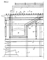
- La Figure 1 est une vue en coupe transversale d'une moitié du four;
- La Figure 2 est une coupe longitudinale de la partie d'enfournement du four, selon II-II de la Figure 1.
- Tel qu'il est représenté au dessin, le four comporte une voûte 1, des parois latérales telles que 2 et une paroi frontale 3 et présente un plan médian longitudinal A-A. Sa sole est formée de longerons fixes réfractaires 4 séparés par des longerons mobiles réfractaires 5 dont la largeur est inférieure à celle des longerons fixes. Des brûleurs non représentés permettent de faire circuler à contre-courant des gaz de combustion dans la zone supérieure du four, au-dessus des longerons 4 et 5.
- Les longerons fixes 4 sont supportés par des profilés métalliques 6 dits "fers sous sole" faisant partie intégrante de l'ossature métallique du four qui est désignée au dessin d'une façon générale par la référence 7. Les longerons mobiles 5 sont de leur côté supportés par des traverses 8, qui, conjointement avec les longerons 9, constituent un châssis mobile. Ce châssis est supporté, par l'intermédiaire de montants 10, par un châssis 11 qui repose sur un châssis 12 par l'intermédiaire de rouleaux 13 et qu'un système de vérins, non représenté, permet de déplacer longitudinalement. Le châssis 12 repose lui-même, par l'intermédiaire de rouleaux 14 sur des plans inclinés fixes 15 et peut être déplacé longitudinalement par un système de vérins également non représenté. En déplaçant le châssis 12 on déplace les longerons mobiles 5 à la fois longitudinalement et verticalement alors que si on déplace le châssis 11, les longerons mobiles 5 ne se meuvent que longitudinalement. En déplaçant simultanément les châssis 11 et 12, on peut imprimer aux longerons mobiles 5 un mouvement circulaire ou rectangulaire qui assure la progression dans le sens de la flèche F des produits 16 reposant sur la sole du four.
- Dans la première partie du four, du côté de l'enfournement, les longerons fixes 4 présentent des évidements tels que 17a et 17b dont la profondeur décroît dans le sens de progression des produits, c'est-à-dire dans le sens de la flèche F à la Figure 2. La plus grande profondeur de ces évidements se trouve donc au niveau de l'enfournement. Dans le mode de réalisation représenté au dessin, l'évidement-17a situé à proximité du plan médian longitudinal A-A a une profondeur plus faible que l'évidement 17b. Les divers évidements sont reliés à un collecteur 18 par des conduits de fumée tels que 19 qui sont supportés par une ossature 20 faisant corps avec le four.
- Etant donné la présence des évidements 17a et 17b ménagés dans les longerons fixes, la section des bordures latérales de ces longerons qui supportent les produits 16, est faible et incompatible avec la pression exercée sur ces bordures. Pour remédier à cet inconvénient, des profilés métalliques 21, de section rectangulaire, sont disposés dans ces bordures, parallèlement à l'axe longitudinal du four. Ces profilés qui servent d'appui aux produits 16 entrant dans le four, reposent sur les fers sous sole 6 par l'intermédiaire de supports 22.
- En fonctionnement, les fumées résultant de la combustion traversent les évidements 17a et 17b, donc le lit de produits auxquels elles cèdent par convection une partie de leur chaleur sensible. En s'écoulant ensuite sous le lit, dans les évidements, elles rayonnent sur les faces inférieures des produits qui sont ainsi chauffées.
- Comme la profondeur des évidements décroît dans le sens de progression des produits, on obtient une bonne répartition, suivant l'axe du four, des fumées ayant traversé le lit de produits. Par ailleurs, l'efficacité du rayonnement thermique sur la face inférieure des produits est maintenue du fait que la baisse de température des fumées, qui circulent à contre-courant, est compensée par un accroissement de leur épaisseur.
- Comme la profondeur des évidements varie également en fonction de leurs positions par rapport à l'axe du four, on peut compenser une dissymétrie éventuelle dans le chauffage du four.
- En définitive, la face inférieure des produits 16 est portée pratiquement à la même température que leur face supérieure et dilate sensiblement de la même valeur. Le cintre des produits es éliminé ou tout au moins considérablement réduit.
- Les produits reposent au droit des longerons fixes 4, sur les profilés 21. Ceux-ci peuvent, sans inconvénients, être métalliques étant donné la température peu élevée qui règne dans le fou dans sa zone d'enfournement.
Claims (4)
caractérisé en ce que les évidements(17a et 17b)débouchent sur la face supérieure des longerons de sorte que les fumées traversent le lit de produits les surmontant.
Applications Claiming Priority (2)
| Application Number | Priority Date | Filing Date | Title |
|---|---|---|---|
| FR8304263A FR2542433B1 (fr) | 1983-03-11 | 1983-03-11 | Fours a longerons refractaires |
| FR8304263 | 1983-03-11 |
Publications (2)
| Publication Number | Publication Date |
|---|---|
| EP0119909A1 true EP0119909A1 (fr) | 1984-09-26 |
| EP0119909B1 EP0119909B1 (fr) | 1987-11-11 |
Family
ID=9286906
Family Applications (1)
| Application Number | Title | Priority Date | Filing Date |
|---|---|---|---|
| EP84400468A Expired EP0119909B1 (fr) | 1983-03-11 | 1984-03-09 | Four à longerons réfractaires |
Country Status (6)
| Country | Link |
|---|---|
| US (1) | US4556385A (fr) |
| EP (1) | EP0119909B1 (fr) |
| CA (1) | CA1218844A (fr) |
| DE (1) | DE3467397D1 (fr) |
| ES (1) | ES286166Y (fr) |
| FR (1) | FR2542433B1 (fr) |
Families Citing this family (7)
| Publication number | Priority date | Publication date | Assignee | Title |
|---|---|---|---|---|
| NL8601467A (nl) * | 1986-06-06 | 1988-01-04 | Elten Nederland | Transportinrichting. |
| IT1248166B (it) * | 1991-05-21 | 1995-01-05 | Danieli Off Mecc | Forno a longheroni refrattari con caricamento centrale per riscaldo edaccumulo di prodotti caldi. |
| DE4119708A1 (de) * | 1991-06-14 | 1992-12-17 | Maerz Ofenbau | Gleichschrittofen fuer die waermebehandlung von stueckigem gut |
| DE4119709A1 (de) * | 1991-06-14 | 1992-12-17 | Maerz Ofenbau | Ofen fuer die waermebehandlung von stueckigem gut |
| US5362230A (en) * | 1993-03-24 | 1994-11-08 | Italimpianti Of America, Inc. | Rolls for high temperature roller hearth furnaces |
| US5370530A (en) * | 1993-03-24 | 1994-12-06 | Italimpianti Of America, Inc. | Rolls for high temperature roller hearth furnaces |
| US5334014A (en) * | 1993-03-30 | 1994-08-02 | Btu International | Walking beam furnace |
Citations (3)
| Publication number | Priority date | Publication date | Assignee | Title |
|---|---|---|---|---|
| US1400367A (en) * | 1919-09-10 | 1921-12-13 | Harry P Mccann | Furnace and method of conveying materials therethrough |
| FR2095628A5 (fr) * | 1970-06-01 | 1972-02-11 | Blocm Engineering Cy | |
| FR2458775A1 (fr) * | 1979-06-09 | 1981-01-02 | Karrena Gmbh | Revetement pour des tubes situes dans des espaces de chauffe de fours industriels |
Family Cites Families (4)
| Publication number | Priority date | Publication date | Assignee | Title |
|---|---|---|---|---|
| US2325757A (en) * | 1942-06-09 | 1943-08-03 | Ehlers Edward | Heating furnace |
| SE338580B (fr) * | 1970-11-04 | 1971-09-13 | Tabougnar Ab | |
| GB2009380B (en) * | 1977-11-01 | 1982-03-31 | Ce Refractories Ltd | Frunaces and furnace components |
| JPS58105468U (ja) * | 1982-01-13 | 1983-07-18 | 中外炉工業株式会社 | アツプセツト付パイプの連続式熱処理炉 |
-
1983
- 1983-03-11 FR FR8304263A patent/FR2542433B1/fr not_active Expired
-
1984
- 1984-03-09 DE DE8484400468T patent/DE3467397D1/de not_active Expired
- 1984-03-09 ES ES1984286166U patent/ES286166Y/es not_active Expired
- 1984-03-09 EP EP84400468A patent/EP0119909B1/fr not_active Expired
- 1984-03-12 US US06/588,860 patent/US4556385A/en not_active Expired - Fee Related
- 1984-03-12 CA CA000449370A patent/CA1218844A/fr not_active Expired
Patent Citations (3)
| Publication number | Priority date | Publication date | Assignee | Title |
|---|---|---|---|---|
| US1400367A (en) * | 1919-09-10 | 1921-12-13 | Harry P Mccann | Furnace and method of conveying materials therethrough |
| FR2095628A5 (fr) * | 1970-06-01 | 1972-02-11 | Blocm Engineering Cy | |
| FR2458775A1 (fr) * | 1979-06-09 | 1981-01-02 | Karrena Gmbh | Revetement pour des tubes situes dans des espaces de chauffe de fours industriels |
Also Published As
| Publication number | Publication date |
|---|---|
| ES286166U (es) | 1985-11-01 |
| CA1218844A (fr) | 1987-03-10 |
| FR2542433A1 (fr) | 1984-09-14 |
| DE3467397D1 (en) | 1987-12-17 |
| US4556385A (en) | 1985-12-03 |
| EP0119909B1 (fr) | 1987-11-11 |
| ES286166Y (es) | 1986-06-01 |
| FR2542433B1 (fr) | 1988-01-29 |
Similar Documents
| Publication | Publication Date | Title |
|---|---|---|
| EP0119909B1 (fr) | Four à longerons réfractaires | |
| US4752268A (en) | Exhaust oven for cathode ray tubes | |
| EP0032203B1 (fr) | Capteur de chaleur pouvant être installé notamment dans une cheminée domestique et procédé pour porter à une température plus élevée un fluide tel que de l'eau | |
| US4300881A (en) | Truck or the like for conveying ceramic articles through a kiln | |
| EP0094455A2 (fr) | Grille pour la combustion de combustibles solides dans des poêles, des foyers, des fourneaux et autres | |
| US4500283A (en) | Infra-red generators and use | |
| US4487138A (en) | Traveling grate for a furnace | |
| FR2536835A1 (fr) | Perfectionnement aux foyers fermes en particulier pour cheminees | |
| EP0148804B1 (fr) | Four à barres pour cuisson rapide en continu ou en intermittent des produits céramiques | |
| US10260812B2 (en) | Grate bar for a pallet car | |
| KR101769322B1 (ko) | 라이더 부재 및 이를 이용한 스키드 장치 | |
| US3437326A (en) | Metal melting and refining furnace | |
| EP0807788B1 (fr) | Grille d'incinération de déchets ménagers | |
| JP4146939B2 (ja) | ステンレス鋼帯の連続焼鈍炉 | |
| US3536307A (en) | Circular traveling grate machine | |
| EP2101132A1 (fr) | Four tunnel | |
| SU1508073A1 (ru) | Колосникова тележка | |
| FR2744005A1 (fr) | Barbecue anti-benzopyrenes a deviation des fumees et gaz chauds | |
| JPS5940437Y2 (ja) | 輻射管付き加熱炉 | |
| SU1183806A1 (ru) | Колосникова тележка | |
| SU1071910A1 (ru) | Печь с шагающим подом | |
| US3173403A (en) | Fabricated steel water-cooled skewback channel with seamless furnace side face | |
| JPS6038658Y2 (ja) | 加熱炉 | |
| FR2544057A1 (fr) | Four pour le rechauffage de brames, lingots, billettes ou autres produits a rechauffer analogues | |
| RU2044244C1 (ru) | Тележка конвейерной обжиговой машины |
Legal Events
| Date | Code | Title | Description |
|---|---|---|---|
| PUAI | Public reference made under article 153(3) epc to a published international application that has entered the european phase |
Free format text: ORIGINAL CODE: 0009012 |
|
| AK | Designated contracting states |
Designated state(s): BE DE GB IT LU NL SE |
|
| 17P | Request for examination filed |
Effective date: 19841022 |
|
| GRAA | (expected) grant |
Free format text: ORIGINAL CODE: 0009210 |
|
| AK | Designated contracting states |
Kind code of ref document: B1 Designated state(s): BE DE GB IT LU NL SE |
|
| ITF | It: translation for a ep patent filed | ||
| REF | Corresponds to: |
Ref document number: 3467397 Country of ref document: DE Date of ref document: 19871217 |
|
| GBT | Gb: translation of ep patent filed (gb section 77(6)(a)/1977) | ||
| PG25 | Lapsed in a contracting state [announced via postgrant information from national office to epo] |
Ref country code: LU Free format text: LAPSE BECAUSE OF NON-PAYMENT OF DUE FEES Effective date: 19880331 |
|
| PLBE | No opposition filed within time limit |
Free format text: ORIGINAL CODE: 0009261 |
|
| STAA | Information on the status of an ep patent application or granted ep patent |
Free format text: STATUS: NO OPPOSITION FILED WITHIN TIME LIMIT |
|
| 26N | No opposition filed | ||
| PGFP | Annual fee paid to national office [announced via postgrant information from national office to epo] |
Ref country code: BE Payment date: 19890228 Year of fee payment: 6 |
|
| PGFP | Annual fee paid to national office [announced via postgrant information from national office to epo] |
Ref country code: SE Payment date: 19890317 Year of fee payment: 6 |
|
| PGFP | Annual fee paid to national office [announced via postgrant information from national office to epo] |
Ref country code: LU Payment date: 19890322 Year of fee payment: 6 |
|
| ITTA | It: last paid annual fee | ||
| PGFP | Annual fee paid to national office [announced via postgrant information from national office to epo] |
Ref country code: NL Payment date: 19890331 Year of fee payment: 6 Ref country code: GB Payment date: 19890331 Year of fee payment: 6 |
|
| PGFP | Annual fee paid to national office [announced via postgrant information from national office to epo] |
Ref country code: DE Payment date: 19890417 Year of fee payment: 6 |
|
| PG25 | Lapsed in a contracting state [announced via postgrant information from national office to epo] |
Ref country code: GB Effective date: 19900309 |
|
| PG25 | Lapsed in a contracting state [announced via postgrant information from national office to epo] |
Ref country code: SE Effective date: 19900310 |
|
| PG25 | Lapsed in a contracting state [announced via postgrant information from national office to epo] |
Ref country code: BE Effective date: 19900331 |
|
| BERE | Be: lapsed |
Owner name: S.A. STEIN HEURTEY Effective date: 19900331 |
|
| PG25 | Lapsed in a contracting state [announced via postgrant information from national office to epo] |
Ref country code: NL Effective date: 19901001 |
|
| GBPC | Gb: european patent ceased through non-payment of renewal fee | ||
| NLV4 | Nl: lapsed or anulled due to non-payment of the annual fee | ||
| PG25 | Lapsed in a contracting state [announced via postgrant information from national office to epo] |
Ref country code: DE Effective date: 19901201 |
|
| EUG | Se: european patent has lapsed |
Ref document number: 84400468.9 Effective date: 19910110 |