EP0119909B1 - Ofen mit Hubbalken aus feuerfestem Material - Google Patents
Ofen mit Hubbalken aus feuerfestem Material Download PDFInfo
- Publication number
- EP0119909B1 EP0119909B1 EP84400468A EP84400468A EP0119909B1 EP 0119909 B1 EP0119909 B1 EP 0119909B1 EP 84400468 A EP84400468 A EP 84400468A EP 84400468 A EP84400468 A EP 84400468A EP 0119909 B1 EP0119909 B1 EP 0119909B1
- Authority
- EP
- European Patent Office
- Prior art keywords
- products
- recesses
- beams
- furnace
- longitudinal
- Prior art date
- Legal status (The legal status is an assumption and is not a legal conclusion. Google has not performed a legal analysis and makes no representation as to the accuracy of the status listed.)
- Expired
Links
- 238000010438 heat treatment Methods 0.000 claims description 7
- 239000002184 metal Substances 0.000 claims description 4
- 230000005855 radiation Effects 0.000 claims description 4
- 239000000779 smoke Substances 0.000 claims description 4
- 230000003247 decreasing effect Effects 0.000 claims description 2
- 239000003517 fume Substances 0.000 description 8
- 238000005452 bending Methods 0.000 description 4
- 239000000567 combustion gas Substances 0.000 description 3
- 230000007423 decrease Effects 0.000 description 2
- 206010022000 influenza Diseases 0.000 description 2
- 235000000396 iron Nutrition 0.000 description 2
- 238000002485 combustion reaction Methods 0.000 description 1
- 230000001627 detrimental effect Effects 0.000 description 1
- 239000000428 dust Substances 0.000 description 1
- 230000008030 elimination Effects 0.000 description 1
- 238000003379 elimination reaction Methods 0.000 description 1
- 239000011819 refractory material Substances 0.000 description 1
- 238000003303 reheating Methods 0.000 description 1
- 230000000284 resting effect Effects 0.000 description 1
- 238000005096 rolling process Methods 0.000 description 1
- XLYOFNOQVPJJNP-UHFFFAOYSA-N water Substances O XLYOFNOQVPJJNP-UHFFFAOYSA-N 0.000 description 1
Images

Classifications
-
- F—MECHANICAL ENGINEERING; LIGHTING; HEATING; WEAPONS; BLASTING
- F27—FURNACES; KILNS; OVENS; RETORTS
- F27B—FURNACES, KILNS, OVENS OR RETORTS IN GENERAL; OPEN SINTERING OR LIKE APPARATUS
- F27B9/00—Furnaces through which the charge is moved mechanically, e.g. of tunnel type; Similar furnaces in which the charge moves by gravity
- F27B9/30—Details, accessories or equipment specially adapted for furnaces of these types
- F27B9/3005—Details, accessories or equipment specially adapted for furnaces of these types arrangements for circulating gases
- F27B9/3011—Details, accessories or equipment specially adapted for furnaces of these types arrangements for circulating gases arrangements for circulating gases transversally
-
- F—MECHANICAL ENGINEERING; LIGHTING; HEATING; WEAPONS; BLASTING
- F27—FURNACES; KILNS; OVENS; RETORTS
- F27B—FURNACES, KILNS, OVENS OR RETORTS IN GENERAL; OPEN SINTERING OR LIKE APPARATUS
- F27B9/00—Furnaces through which the charge is moved mechanically, e.g. of tunnel type; Similar furnaces in which the charge moves by gravity
- F27B9/14—Furnaces through which the charge is moved mechanically, e.g. of tunnel type; Similar furnaces in which the charge moves by gravity characterised by the path of the charge during treatment; characterised by the means by which the charge is moved during treatment
- F27B9/20—Furnaces through which the charge is moved mechanically, e.g. of tunnel type; Similar furnaces in which the charge moves by gravity characterised by the path of the charge during treatment; characterised by the means by which the charge is moved during treatment the charge moving in a substantially straight path
- F27B9/201—Furnaces through which the charge is moved mechanically, e.g. of tunnel type; Similar furnaces in which the charge moves by gravity characterised by the path of the charge during treatment; characterised by the means by which the charge is moved during treatment the charge moving in a substantially straight path walking beam furnace
- F27B9/202—Conveyor mechanisms therefor
- F27B9/203—Conveyor mechanisms therefor having ramps
-
- F—MECHANICAL ENGINEERING; LIGHTING; HEATING; WEAPONS; BLASTING
- F27—FURNACES; KILNS; OVENS; RETORTS
- F27D—DETAILS OR ACCESSORIES OF FURNACES, KILNS, OVENS OR RETORTS, IN SO FAR AS THEY ARE OF KINDS OCCURRING IN MORE THAN ONE KIND OF FURNACE
- F27D3/00—Charging; Discharging; Manipulation of charge
- F27D3/02—Skids or tracks for heavy objects
- F27D3/022—Skids
- F27D3/024—Details of skids, e.g. riders
Definitions
- Ovens intended for continuous heating, before rolling of products such as billets or blooms are often with mobile beams.
- a part of the sole is formed of fixed beams while the remaining part consists of mobile beams and has a circular or rectangular movement.
- the products rest alternately on the fixed beams and on the mobile beams whose movement ensures the progression of these products.
- the beams of these ovens can be hollow and cooled by water circulation. They can also be made of refractory material, which reduces the thermal consumption of the furnace, given the elimination of thermal losses from the cooled elements.
- the products are heated mainly by the radiation from the furnace on their upper face and on their lateral faces.
- Their lower face which is constantly in contact with the refractory hearth, is heated only by the thermal conduction coming from the other faces and, in most of the oven, is at a temperature lower than that of the rest of the product.
- This temperature difference causes a difference in expansion of the upper and lower faces of the product, which causes it to bend in the vertical plane.
- This bending is detrimental to the progression of the products on the floor; in fact, the bent products tend to tip over and then risk overlapping if the deflection of the bending is greater than the interval which separates two successive products.
- the patent U. S. 1,400,367 describes an oven comprising a hearth provided with slots in which are engaged mobile beams separated by a fixed beam of width greater than that of the mobile beams.
- the side walls of the slots open flues bringing the combustion gases; these circulate around the movable elements of the floor and prevent cold air from entering through the slits.
- the combustion gases and the fumes exiting through slots which have a limited width cannot heat the underside of the products, therefore preventing their bending.
- the side walls of the slots and those of the mobile side members are in contact with the fumes and dust they contain; this is a drawback given the relative movement of the walls of the slots and those of the side members.
- the present invention relates to an oven with refractory beams, with higher heating, which on the contrary makes it possible to avoid practically any bending of the products.
- This oven in which the fixed beams of the hearth have a width greater than that of the mobile beams and have recesses connected to the general smoke circuit, is characterized in that the recesses open onto the upper face of the beams being oriented in the direction longitudinal of these beams, and are framed by portions of the fixed beams of width less than that of said recesses or by the walls of the furnace, so that the fumes cross the bed of products overcoming them, pass under this bed by heating by radiation the underside of said products, and are then evacuated outside.
- the recesses preferably have a decreasing depth in the direction of movement of the products. They thus have an increasing passage section with the direction of flow of the fumes, which compensates for their drop in temperature.
- the recesses can have different depths, the depth of a recess being a function of its position relative to the longitudinal median plane of the furnace. Smoke flows are thus obtained under the products, therefore reheating the underside of these products, which depend on the place of said products relative to the axis of the oven. It is thus possible to compensate for an asymmetry in the heating of the oven.
- the fixed longitudinal members may include longitudinal metal profiles capable of supporting the products and themselves supported by the lower frame of the oven.
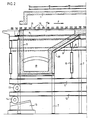
- the oven has a roof 1, side walls such as 2 and a front wall 3 and has a longitudinal median plane A-A. Its sole is formed of refractory fixed beams 4 separated by mobile refractory beams 5 whose width is less than that of the fixed beams. Burners, not shown, make it possible to circulate combustion gases against the current in the upper zone of the furnace, above the longitudinal members 4 and 5.
- the fixed longitudinal members 4 are supported by metal profiles 6 known as “sole irons forming an integral part of the metallic framework of the furnace which is designated in the drawing generally by the reference 7.
- the mobile longitudinal members 5 are on their side supported by crosspieces 8, which, together with the side members 9, constitute a movable frame.
- This chassis is supported, by means of uprights 10, by a chassis 11 which rests on a frame 12 by means of rollers 13 and which a system of jacks, not shown, makes it possible to move longitudinally.
- the frame 12 rests itself, by means of rollers 14 on fixed inclined planes 15 and can be moved longitudinally by a system of jacks also not shown.
- the movable beams 5 are moved both longitudinally and vertically, while if the chassis 11 is moved, the movable beams 5 only move longitudinally.
- the fixed rails 4 have recesses such as 17a and 17b whose depth decreases in the direction of progression of the products, that is to say in the direction of the arrow F in Figure 2.
- the greatest depth of these recesses is therefore at the level of the oven.
- the recess 17a located near the longitudinal median plane A-A has a shallower depth than the recess 17b.
- the various recesses are connected to a manifold 18 by flues such as 19 which are supported by a frame 20 integral with the oven.
- the fumes resulting from the combustion pass through the recesses 17a and 17b, therefore the bed of products to which they give up by convection part of their sensible heat. Then flowing under the bed, in the recesses, they radiate on the undersides of the products which are thus heated.
- the depth of the recesses also varies as a function of their positions relative to the axis of the oven, it is possible to compensate for any asymmetry in the heating of the oven.
- the underside of the products 16 is brought to practically the same temperature as their upper face and expands substantially by the same value.
- the product hanger is eliminated or at least considerably reduced.
Landscapes
- Engineering & Computer Science (AREA)
- Mechanical Engineering (AREA)
- General Engineering & Computer Science (AREA)
- Heat Treatments In General, Especially Conveying And Cooling (AREA)
- Tunnel Furnaces (AREA)
Claims (4)
Applications Claiming Priority (2)
| Application Number | Priority Date | Filing Date | Title |
|---|---|---|---|
| FR8304263 | 1983-03-11 | ||
| FR8304263A FR2542433B1 (fr) | 1983-03-11 | 1983-03-11 | Fours a longerons refractaires |
Publications (2)
| Publication Number | Publication Date |
|---|---|
| EP0119909A1 EP0119909A1 (de) | 1984-09-26 |
| EP0119909B1 true EP0119909B1 (de) | 1987-11-11 |
Family
ID=9286906
Family Applications (1)
| Application Number | Title | Priority Date | Filing Date |
|---|---|---|---|
| EP84400468A Expired EP0119909B1 (de) | 1983-03-11 | 1984-03-09 | Ofen mit Hubbalken aus feuerfestem Material |
Country Status (6)
| Country | Link |
|---|---|
| US (1) | US4556385A (de) |
| EP (1) | EP0119909B1 (de) |
| CA (1) | CA1218844A (de) |
| DE (1) | DE3467397D1 (de) |
| ES (1) | ES286166Y (de) |
| FR (1) | FR2542433B1 (de) |
Families Citing this family (7)
| Publication number | Priority date | Publication date | Assignee | Title |
|---|---|---|---|---|
| NL8601467A (nl) * | 1986-06-06 | 1988-01-04 | Elten Nederland | Transportinrichting. |
| IT1248166B (it) * | 1991-05-21 | 1995-01-05 | Danieli Off Mecc | Forno a longheroni refrattari con caricamento centrale per riscaldo edaccumulo di prodotti caldi. |
| DE4119709A1 (de) * | 1991-06-14 | 1992-12-17 | Maerz Ofenbau | Ofen fuer die waermebehandlung von stueckigem gut |
| DE4119708A1 (de) * | 1991-06-14 | 1992-12-17 | Maerz Ofenbau | Gleichschrittofen fuer die waermebehandlung von stueckigem gut |
| US5370530A (en) * | 1993-03-24 | 1994-12-06 | Italimpianti Of America, Inc. | Rolls for high temperature roller hearth furnaces |
| US5362230A (en) * | 1993-03-24 | 1994-11-08 | Italimpianti Of America, Inc. | Rolls for high temperature roller hearth furnaces |
| US5334014A (en) * | 1993-03-30 | 1994-08-02 | Btu International | Walking beam furnace |
Family Cites Families (7)
| Publication number | Priority date | Publication date | Assignee | Title |
|---|---|---|---|---|
| US1400367A (en) * | 1919-09-10 | 1921-12-13 | Harry P Mccann | Furnace and method of conveying materials therethrough |
| US2325757A (en) * | 1942-06-09 | 1943-08-03 | Ehlers Edward | Heating furnace |
| US3647194A (en) * | 1970-06-01 | 1972-03-07 | Bloom Eng Co Inc | Protective refractory member |
| SE338580B (de) * | 1970-11-04 | 1971-09-13 | Tabougnar Ab | |
| GB2009380B (en) * | 1977-11-01 | 1982-03-31 | Ce Refractories Ltd | Frunaces and furnace components |
| DE2923540C3 (de) * | 1979-06-09 | 1985-06-27 | Karrena GmbH, 4000 Düsseldorf | Rohrverkleidung für Rohre in Feuerungsräumen von Industrieöfen |
| JPS58105468U (ja) * | 1982-01-13 | 1983-07-18 | 中外炉工業株式会社 | アツプセツト付パイプの連続式熱処理炉 |
-
1983
- 1983-03-11 FR FR8304263A patent/FR2542433B1/fr not_active Expired
-
1984
- 1984-03-09 EP EP84400468A patent/EP0119909B1/de not_active Expired
- 1984-03-09 ES ES1984286166U patent/ES286166Y/es not_active Expired
- 1984-03-09 DE DE8484400468T patent/DE3467397D1/de not_active Expired
- 1984-03-12 US US06/588,860 patent/US4556385A/en not_active Expired - Fee Related
- 1984-03-12 CA CA000449370A patent/CA1218844A/fr not_active Expired
Also Published As
| Publication number | Publication date |
|---|---|
| ES286166Y (es) | 1986-06-01 |
| EP0119909A1 (de) | 1984-09-26 |
| FR2542433B1 (fr) | 1988-01-29 |
| ES286166U (es) | 1985-11-01 |
| DE3467397D1 (en) | 1987-12-17 |
| FR2542433A1 (fr) | 1984-09-14 |
| CA1218844A (fr) | 1987-03-10 |
| US4556385A (en) | 1985-12-03 |
Similar Documents
| Publication | Publication Date | Title |
|---|---|---|
| EP0119909B1 (de) | Ofen mit Hubbalken aus feuerfestem Material | |
| US4752268A (en) | Exhaust oven for cathode ray tubes | |
| EP0032203B1 (de) | Wärmeabfang, insbesondere für offene Kamine, und Verfahren zum Erwärmen eines Fluidums, wie z.B. Wasser | |
| EP1868440A1 (de) | Vorrichtung zum backen von pizzas und grillen | |
| US4300881A (en) | Truck or the like for conveying ceramic articles through a kiln | |
| FR2530926A1 (fr) | Four de boulangerie compact pour cuisson au defile | |
| FR2536835A1 (fr) | Perfectionnement aux foyers fermes en particulier pour cheminees | |
| US10260812B2 (en) | Grate bar for a pallet car | |
| FR2744005A1 (fr) | Barbecue anti-benzopyrenes a deviation des fumees et gaz chauds | |
| FR2480923A1 (fr) | Toit de four a arc | |
| EP0807788B1 (de) | Rostanordnung zum Verbrennen von Hausmüll | |
| US3536307A (en) | Circular traveling grate machine | |
| JP4146939B2 (ja) | ステンレス鋼帯の連続焼鈍炉 | |
| FR2557965A1 (fr) | Four a barres pour cuisson rapide en continu ou en intermittent des produits ceramiques | |
| SU1183806A1 (ru) | Колосникова тележка | |
| US3173403A (en) | Fabricated steel water-cooled skewback channel with seamless furnace side face | |
| EP0219482B1 (de) | Haubenofen | |
| BE370399A (de) | ||
| SU1508073A1 (ru) | Колосникова тележка | |
| BE537808A (de) | ||
| FR2687769A1 (fr) | Procede de chauffage d'un objet chaud metallique, en particulier de brames minces, toles et bandes en acier, dans des fours a rouleaux a haute temperature. | |
| FR2477376A1 (fr) | Chariot pour four de boulangerie, patisserie, ou analogue, a recyclage d'air | |
| FR2478271A1 (fr) | Dispositif amovible recuperateur de chaleur pour atre de cheminee | |
| CH330750A (fr) | Dispositif formant joint étance d'une fente de four et servant de support pour des objets destinés à être placés dans ce four | |
| FR2558338A1 (fr) | Four de cuisson |
Legal Events
| Date | Code | Title | Description |
|---|---|---|---|
| PUAI | Public reference made under article 153(3) epc to a published international application that has entered the european phase |
Free format text: ORIGINAL CODE: 0009012 |
|
| AK | Designated contracting states |
Designated state(s): BE DE GB IT LU NL SE |
|
| 17P | Request for examination filed |
Effective date: 19841022 |
|
| GRAA | (expected) grant |
Free format text: ORIGINAL CODE: 0009210 |
|
| AK | Designated contracting states |
Kind code of ref document: B1 Designated state(s): BE DE GB IT LU NL SE |
|
| ITF | It: translation for a ep patent filed | ||
| REF | Corresponds to: |
Ref document number: 3467397 Country of ref document: DE Date of ref document: 19871217 |
|
| GBT | Gb: translation of ep patent filed (gb section 77(6)(a)/1977) | ||
| PG25 | Lapsed in a contracting state [announced via postgrant information from national office to epo] |
Ref country code: LU Free format text: LAPSE BECAUSE OF NON-PAYMENT OF DUE FEES Effective date: 19880331 |
|
| PLBE | No opposition filed within time limit |
Free format text: ORIGINAL CODE: 0009261 |
|
| STAA | Information on the status of an ep patent application or granted ep patent |
Free format text: STATUS: NO OPPOSITION FILED WITHIN TIME LIMIT |
|
| 26N | No opposition filed | ||
| PGFP | Annual fee paid to national office [announced via postgrant information from national office to epo] |
Ref country code: BE Payment date: 19890228 Year of fee payment: 6 |
|
| PGFP | Annual fee paid to national office [announced via postgrant information from national office to epo] |
Ref country code: SE Payment date: 19890317 Year of fee payment: 6 |
|
| PGFP | Annual fee paid to national office [announced via postgrant information from national office to epo] |
Ref country code: LU Payment date: 19890322 Year of fee payment: 6 |
|
| ITTA | It: last paid annual fee | ||
| PGFP | Annual fee paid to national office [announced via postgrant information from national office to epo] |
Ref country code: NL Payment date: 19890331 Year of fee payment: 6 Ref country code: GB Payment date: 19890331 Year of fee payment: 6 |
|
| PGFP | Annual fee paid to national office [announced via postgrant information from national office to epo] |
Ref country code: DE Payment date: 19890417 Year of fee payment: 6 |
|
| PG25 | Lapsed in a contracting state [announced via postgrant information from national office to epo] |
Ref country code: GB Effective date: 19900309 |
|
| PG25 | Lapsed in a contracting state [announced via postgrant information from national office to epo] |
Ref country code: SE Effective date: 19900310 |
|
| PG25 | Lapsed in a contracting state [announced via postgrant information from national office to epo] |
Ref country code: BE Effective date: 19900331 |
|
| BERE | Be: lapsed |
Owner name: S.A. STEIN HEURTEY Effective date: 19900331 |
|
| PG25 | Lapsed in a contracting state [announced via postgrant information from national office to epo] |
Ref country code: NL Effective date: 19901001 |
|
| GBPC | Gb: european patent ceased through non-payment of renewal fee | ||
| NLV4 | Nl: lapsed or anulled due to non-payment of the annual fee | ||
| PG25 | Lapsed in a contracting state [announced via postgrant information from national office to epo] |
Ref country code: DE Effective date: 19901201 |
|
| EUG | Se: european patent has lapsed |
Ref document number: 84400468.9 Effective date: 19910110 |