EP0119921A1 - Electrovalve à trois voies - Google Patents
Electrovalve à trois voies Download PDFInfo
- Publication number
- EP0119921A1 EP0119921A1 EP84400519A EP84400519A EP0119921A1 EP 0119921 A1 EP0119921 A1 EP 0119921A1 EP 84400519 A EP84400519 A EP 84400519A EP 84400519 A EP84400519 A EP 84400519A EP 0119921 A1 EP0119921 A1 EP 0119921A1
- Authority
- EP
- European Patent Office
- Prior art keywords
- solenoid valve
- valves
- spacer
- axis
- valve
- Prior art date
- Legal status (The legal status is an assumption and is not a legal conclusion. Google has not performed a legal analysis and makes no representation as to the accuracy of the status listed.)
- Granted
Links
Images
Classifications
-
- B—PERFORMING OPERATIONS; TRANSPORTING
- B60—VEHICLES IN GENERAL
- B60T—VEHICLE BRAKE CONTROL SYSTEMS OR PARTS THEREOF; BRAKE CONTROL SYSTEMS OR PARTS THEREOF, IN GENERAL; ARRANGEMENT OF BRAKING ELEMENTS ON VEHICLES IN GENERAL; PORTABLE DEVICES FOR PREVENTING UNWANTED MOVEMENT OF VEHICLES; VEHICLE MODIFICATIONS TO FACILITATE COOLING OF BRAKES
- B60T13/00—Transmitting braking action from initiating means to ultimate brake actuator with power assistance or drive; Brake systems incorporating such transmitting means, e.g. air-pressure brake systems
- B60T13/02—Transmitting braking action from initiating means to ultimate brake actuator with power assistance or drive; Brake systems incorporating such transmitting means, e.g. air-pressure brake systems with mechanical assistance or drive
- B60T13/04—Transmitting braking action from initiating means to ultimate brake actuator with power assistance or drive; Brake systems incorporating such transmitting means, e.g. air-pressure brake systems with mechanical assistance or drive by spring or weight
-
- Y—GENERAL TAGGING OF NEW TECHNOLOGICAL DEVELOPMENTS; GENERAL TAGGING OF CROSS-SECTIONAL TECHNOLOGIES SPANNING OVER SEVERAL SECTIONS OF THE IPC; TECHNICAL SUBJECTS COVERED BY FORMER USPC CROSS-REFERENCE ART COLLECTIONS [XRACs] AND DIGESTS
- Y10—TECHNICAL SUBJECTS COVERED BY FORMER USPC
- Y10T—TECHNICAL SUBJECTS COVERED BY FORMER US CLASSIFICATION
- Y10T137/00—Fluid handling
- Y10T137/8593—Systems
- Y10T137/86493—Multi-way valve unit
- Y10T137/86574—Supply and exhaust
- Y10T137/86622—Motor-operated
-
- Y—GENERAL TAGGING OF NEW TECHNOLOGICAL DEVELOPMENTS; GENERAL TAGGING OF CROSS-SECTIONAL TECHNOLOGIES SPANNING OVER SEVERAL SECTIONS OF THE IPC; TECHNICAL SUBJECTS COVERED BY FORMER USPC CROSS-REFERENCE ART COLLECTIONS [XRACs] AND DIGESTS
- Y10—TECHNICAL SUBJECTS COVERED BY FORMER USPC
- Y10T—TECHNICAL SUBJECTS COVERED BY FORMER US CLASSIFICATION
- Y10T137/00—Fluid handling
- Y10T137/8593—Systems
- Y10T137/86919—Sequentially closing and opening alternately seating flow controllers
-
- Y—GENERAL TAGGING OF NEW TECHNOLOGICAL DEVELOPMENTS; GENERAL TAGGING OF CROSS-SECTIONAL TECHNOLOGIES SPANNING OVER SEVERAL SECTIONS OF THE IPC; TECHNICAL SUBJECTS COVERED BY FORMER USPC CROSS-REFERENCE ART COLLECTIONS [XRACs] AND DIGESTS
- Y10—TECHNICAL SUBJECTS COVERED BY FORMER USPC
- Y10T—TECHNICAL SUBJECTS COVERED BY FORMER US CLASSIFICATION
- Y10T137/00—Fluid handling
- Y10T137/8593—Systems
- Y10T137/87169—Supply and exhaust
- Y10T137/87217—Motor
-
- Y—GENERAL TAGGING OF NEW TECHNOLOGICAL DEVELOPMENTS; GENERAL TAGGING OF CROSS-SECTIONAL TECHNOLOGIES SPANNING OVER SEVERAL SECTIONS OF THE IPC; TECHNICAL SUBJECTS COVERED BY FORMER USPC CROSS-REFERENCE ART COLLECTIONS [XRACs] AND DIGESTS
- Y10—TECHNICAL SUBJECTS COVERED BY FORMER USPC
- Y10T—TECHNICAL SUBJECTS COVERED BY FORMER US CLASSIFICATION
- Y10T137/00—Fluid handling
- Y10T137/8593—Systems
- Y10T137/877—With flow control means for branched passages
- Y10T137/87708—With common valve operator
- Y10T137/87772—With electrical actuation
Definitions
- the invention relates to a three-way and three-position solenoid valve, offering a general structure with symmetry of revolution about an axis and comprising a magnetic armature movable in translation along this axis under the action of an electromagnetic coil and d '' a return spring, this armature being hollow and internally comprising two valves situated on said axis, movable with respect to each other and with respect to the armature, separated from one another by a spring and provided with flanges by means of which they can be moved by the movable frame with respect to fixed respective seats which they are capable of closing.
- FR-A-.2 259 303.
- the subject of the invention is a solenoid valve of the type defined above, in which the movable armature actuates each valve, to apply it to its respective seat, by means of the flange of the other valve and of a spacer disposed between the valves, this spacer coming to bear with point contact on the internal end of one of the valves.
- This punctual contact avoids any undesirable oblique position of one or the other valve when it comes to present itself in front of its seat to close it.
- each valve can only maintain a precise alignment facing its seat. The aforementioned point contact should take place at a point located substantially on the axis of symmetry of the solenoid valve.
- the spacer can be constituted by an independent piece freely interposed between the valves.
- This spacer designed to come to bear with a point contact on one of the valves, can also be made integral with the other valve, either fixed thereto, or being integral with it.
- the point contact is made between a flat surface perpendicular to the axis of symmetry and a convex surface belonging one to the valve and the other to the spacer.
- this curved surface belongs to the spacer and the planar surface to the valve, the latter then being able to be formed by the end face of the flange of this valve.
- the curved surface is advantageously formed by a spherical ball.
- these balls and the point contact ball, aligned on the axis of symmetry may be identical.
- the arrangement according to the invention makes it possible to provide that the valves are retained in the movable frame by simple interposition of all of their flanges between a pair of valve guide rings, only one of these rings being fixed so removable in the mobile frame. This leads to a particularly easy method of mounting the valves in the movable frame.
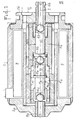
- Figure 1 shows in axial section an electrovalve according to the invention.
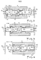
- FIGS 2 to 4 schematically represent the three operating positions of the solenoid valve of Figure 1.
- the three-way solenoid shown in Figure 1 the overall structure has a symmetry of revolution about an axis 1, comprises, in a casing 2, an electromagnetic coil 3 is capable of MOVE - cer in translation in the axis 1 a movable frame 4.
- This is hollow and internally comprises guide rings 4a, 4b in which two valves 56a, 56b can slide, respectively, constituted by cylindrical parts 5a, 5b carrying at their outer end balls 6a, 6b, each of which can close off a respective seat 7a, 7b, these seats appearing at the internal ends of the tubes 8a, 8b shown coaxially with the axis 1 in end flanges 2a, 2b of the housing 2.
- each tubing 8a, 8b can be either closed, or connected to a third tubing 9 (by means of passages provided for this purpose around and through the movable frame 4).
- the movable frame 4 is biased to the left (as shown in Figure 1) by a return spring 10, while the coil 3, excited by an electric current, biases it to the right.
- the cylindrical parts 5a, 5b have, at their end closest to the center of the frame 4, a flange 11a, 11b, each of which can cooperate with the respective guide ring 4a, 4b.
- the parts 5a, 5b and consequently their balls 6a, 6b are spaced apart by a compression spring 12 interposed between the flanges 11a, 11b.
- the part 5a is extended, beyond its flange 11a, by a spacer 13 integral with said flange, which carries at its end a ball 14 capable of coming into punctual contact with the center C of the flange 11b of the other part 5b, this point being located substantially on axis 1.
- the dimensioning of the parts is calculated so that there remains in this first extreme position a non-zero air gap 15 between the frame 4 and the left flange 2a. In this position, the spring 12, less strong than the spring 10, is compressed by the latter between the flanges 11a and 11b.
- valves 56a, 56b are pushed, due to the movement of the frame 4, by means not of their respective flange 11a, 11b, but of the ball 14 in punctual contact with the flange 11b of the part 5b (FIGS. 2 and 4), which ensures automatic alignment of the valves 56a, 56b on the axis 1 and therefore of their balls 6a, 6b on the seats 7a, 7b of these. This ensures that the solenoid valve operates flawlessly and without leakage in all circumstances.
- the corresponding structure of the movable assembly formed by the frame 4 and the valves 56a, 56b provides a very simple and easy assembly thereof. It suffices to introduce the valve 56b into the guide ring 4b, which is integral with the frame 4, then the valve 56a after interposition of the spring 12, and finally to screw the guide ring 4a into the frame 4 thanks to a thread 17 provided for this purpose.
- a solenoid valve as described finds application for example in anti-skid braking systems for motor vehicles.
- the tubing 9 being connected to a brake cylinder, the tubing 8b to the source of pressurized fluid and the tubing 8a to the cover of the system or to the atmosphere, the first position of the solenoid valve corresponds to a braking phase, the second position to a release phase of braking and the intermediate position to a phase of maintaining the existing braking force.
Landscapes
- Engineering & Computer Science (AREA)
- Physics & Mathematics (AREA)
- Fluid Mechanics (AREA)
- Transportation (AREA)
- Mechanical Engineering (AREA)
- Magnetically Actuated Valves (AREA)
- Multiple-Way Valves (AREA)
Abstract
Description
- L'invention se rapporte à une electrovalve à trois voies et trois positions, offrant une structure générale à symétrie de révolution autour d'un axe et comportant une armature magnétique mobile en translation suivant cet axe sous l'action d'une bobine électromagnétique et d'un ressort de rappel, cette armature étant creuse et comportant intérieurement deux clapets situés sur ledit axe, mobiles l'un par rapport à l'autre et par rapport à l'armature,_écartés l'un de l'autre par un ressort et munis de brides par l'intermédiaire desquelles ils peuvent être déplacés par l'armature mobile vis-à-vis de sièges respes- tifs fixes qu'ils sont susceptibles d'obturer . Comme par exemple dans la demande de brevet FR-A-.2 259 303 . ,
- Dans des électrovalves connues de ce genre, l'armature mobile pousse chacun des clapets dans sa position d'obturation directement par sa bride . Il en résulte que tout défaut d'usinage ou de montage de ces éléments peut- être cause d'un désalignement angulaire du clapet, qui ne se présente alors pas rigoureusement en face du siège qu'il doit obturer, de sorte qu'il y a risque d'obturation défectueuse et, par suite de fuite du fluide(pneumatique ou hydraulique) appliqué à l'électrovalve .
- Par ailleurs, un tel mode d'action de l'armature sur les clapets nécessite de prévoir, entre les brides des clapets, une entretoise tubulaire solidaire de l'armature, cette entretoise coopérant avec l'une ou l'autre des brides pour transmettre au clapet correspondant la force de poussée de l'armature mobile en direction du siège de celui-ci . Une telle disposition complique le montage des clapets dans l'armature mobile .
- Dans le but de remédier à ces inconvénients, l'invention a pour objet une électrovalve du genre défini ci-dessus, dans laquelle l'armature mobile actionne chaque clapet, pour l'appliquer sur son siège respectifs, par l'intermédiaire de la bride de l'autre clapet et d'une entretoise disposée entre les clapets, cette entretoise venant s'appuyer avec contact ponctuel sur l'extrémité interne de l'un des clapets. Ce contact ponctuel évite toute position oblique indésirable de l'un ou l'autre clapet lorsqu'il vient se présenter devant son siège pour en réaliser l'obturation. Au contraire, chaque clapet ne peut que conserver un alignement précis face à son siège. Il convient que le contact ponctuel précité ait lieu en un point situé sensiblement sur l'axe de symétrie de l'électrovalve.
- L'entretoise peut être constituée par une pièce indépendante librement interposée entre les clapets. Cette entretoise, conçue pour venir s'appuyer avec un contact ponctuel sur l'un des clapets, peut encore être rendue solidaire de l'autre clapet, soit fixée à celui-ci, soit faisant corps avec lui.
- Avantageusement le contact ponctuel est réalisé entre une surface plane perpendiculaire à l'axe de symétrie et une surface bombée appartenant l'une au clapet et l'autre à l'entretoise. De préférence, cette surface bombée appartient à l'entretoise et la surface plane au clapet, cette dernière pouvant alors être constituée par la face terminale de la bride de ce clapet. La surface bombée est avantageusement formée par une bille sphérique. Dans ce cas, lorsque les organes d'obturation des clapets sont constitués par des billes, ces billes et la bille de contact ponctuel, alignées sur l'axe de symétrie, peuvent être identiques.
- La disposition selon l'invention permet de prévoir que les clapets soient retenus dans l'armature mobile par simple interposition de l'ensemble de leurs brides entre une paire de bagues de guidage des clapets, seule l'une de ces bagues étant fixée de manière démontable dans l'armature mobile. Cela conduit à un mode de montage particulièrement aisé des clapets dans l'armature mobile.
- D'autres caractéristiques et avantages de l'invention seront mieux compris à la lecture de la description qui va suivre, en regard des dessins annexés, d'un exemple de réalisation non limitatif.
- La figure 1 représente en coupe axiale une électrovalve selon l'invention.
- Les figures 2 à 4 représentent schématiquement les trois positions de fonctionnement de l'électrovalve de la figure 1.
- L'électrovalve à trois voies représentée à la figure 1, dont la structure générale présente une symétrie de révolution autour d'un axe 1, comporte, dans un boîtier 2, une bobine électromagnétique 3 capable de faire se dépla- cer en translation suivant l'axe 1 une armature mobile 4. Celle-ci est creuse et comporte intérieurement des bagues de guidage 4a, 4b dans lesquelles peuvent coulisser respectivement deux clapets 56a, 56b constitués par des pièces cylindriques 5a, 5b portant à leur extrémité extérieure des billes 6a, 6b dont chacune peut venir obturer un siège respectif 7a, 7b, ces sièges apparaissant aux extrémités internes de.tubulures 8a, 8b montrés coaxialement à l'axe 1 dans des flasques d'extrémités 2a, 2b du boîtier 2. Suivant celle des trois positions que prend l'armature mobile 4, chaque tubulure 8a, 8b peut être soit obturée, soit reliée à une troisième tubulure 9 (par l'intermédiaire de passages prévus à cet effet autour et à travers l'armature mobile 4).
- L'armature mobile 4 est sollicitée vers la gauche (suivant la représentation de la figure 1) par un ressort de rappel 10, tandis que la bobine 3, excitée par un courant électrique, la sollicite vers la droite. Les pièces cylindriques 5a, 5b comportent, à leur extrémité la plus proche du centre de l'armature 4, une bride 11a, 11b dont chacune peut coopérer avec la bague de guidage 4a, 4b respective. Les pièces 5a, 5b et par suite leurs billes 6a, 6b sont écartées mutuellement par un ressort de compression 12 interposé entre les brides 11a, 11b.
- La pièce 5a se prolonge, au delà de sa bride 11a, par une entretoise 13 solidaire de ladite bride, qui porte à son extrémité une bille 14 susceptible de venir en contact ponctuel avec le centre C de la bride 11b de l'autre pièce 5b, ce point étant situé sensiblement sur l'axe 1.
- Le fonctionnement de l'électrovalve va maintenant être expliqué à l'aide des figures schématiques 2 à 4. Lorsque la bobine 3 (non représentée sur ces figures) n'est pas excitée, l'armature mobile est repoussée à gauche par le ressort 10 dans sa position de repos, définie par la venue en butée de la bague de guidage 4b sur la bride 11b du clapet 56b, de cette bride 11b sur la bille 14 appartenant à l'entretoise 13 et de la bille 6a appartenant au clapet 56a sur son siège 7a, tandis qu'en même temps le clapet 56b se trouve tiré vers la gauche par sa bride 11b, de sorte que la bille 6b de ce clapet est écartée de son siège 7b. La tubulure 8b est alors reliée à la tubulure 9 (non représentée), la tubulure 8a étant obturée. Afin d'éviter tout collage intempestif de l'armature 4, le dimensionnement des pièces est calculé de manière qu'il subsiste dans cette première position extrême un entrefer 15 non nul entre l'armature 4 et le flasque de gauche 2a. Dans cette position, le ressort 12, moins fort que le ressort 10, se trouve comprimé par ce dernier entre les brides 11a et 11b.
- Lorsqu'on soumet la bobine 3 à une demi-excita-- tion, elle fait se déplacer l'armature 4 vers la droite dans une position intermédiaire d'équilibre à l'encontre de la force du ressort 10 légèrement comprimé. Dans cette position (fig. 3) la bride 11a est butée sur la bague de guidage 4a tandis que la bride 11b reste dégagée de la bague de guidage 4b. Le ressort 12 se met en extension et applique les billes 6a, 6b sur leurs sièges 7a, 7b, tandis que la bille 14 quitte la bride 11b. Les deux tubulures 8a et 8b sont alors obturées.
- Si l'on applique à la bobine 3 sa pleine excitation, elle déplace l'armature 4 vers la droite, avec compression du ressort 12, jusque dans sa seconde position extrême (fig. 4) définie par la venue en butée de la bague de guidage 4a sur la bride 11a du clapet 56a, et de la bille 14 appartenant à l'entretoise 13 sur la bride 11b du clapet 56b la bille 6b de ce dernier venant obturer la tubulure 8b, tandis que la tubulure 8a est mise en communication avec la tubulure 9. Les éléments sont dimensionnés pour qu'ici aussi demeure un entrefer 16 non nul, entre l'armature 4 et le flasque de droite 2b.
- On constate que, pour venir dans leur position respective d'obturation, les clapets 56a, 56b sont poussés, du fait du déplacement de l'armature 4, par l'intermédiaire non pas de leur bride respective 11a, 11b, mais de la bille 14 en contact ponctuel avec la bride 11b de la pièce 5b (figure 2 et 4), ce qui assure un alignement automatique des clapets 56a, 56b sur l'axe 1 et donc de leurs billes 6a, 6b sur les sièges 7a, 7b de celles-ci. Cela assure à l'électrovalve un fonctionnement parfait et sans fuite en toutes circonstances.
- De plus, la structure correspondante de l'équipage mobile formé par l'armature 4 et les clapets 56a, 56b procure un assemblage très simple et aisé de celui-ci. Il suffit d'introduire le clapet 56b dans la bague de guidage 4b, qui fait corps avec l'armature 4, puis le clapet 56a après interposition du ressort 12, et enfin de visser dans l'armature 4 la bague de guidage 4a grâce à un filetage 17 prévu à cet effet.
- Une électrovalve telle que décrite trouve application par exemple dans les systèmes de freinage antipatinants pour véhicules automobiles. La tubulure 9 étant raccordée à un cylindre de frein, la tubulure 8b à la source de fluide sous pression et la tubulure 8a à la bâche du système ou à l'atmosphère, la première position de l'électrovalve correspond à une phase de freinage, la seconde position à une phase de relâchement du freinage et la position intermédiaire à une phase de maintien de la-force de freinage existante.
Claims (9)
Applications Claiming Priority (2)
| Application Number | Priority Date | Filing Date | Title |
|---|---|---|---|
| FR8304581 | 1983-03-21 | ||
| FR8304581A FR2543252B1 (fr) | 1983-03-21 | 1983-03-21 | Electrovalve a trois voies |
Publications (2)
| Publication Number | Publication Date |
|---|---|
| EP0119921A1 true EP0119921A1 (fr) | 1984-09-26 |
| EP0119921B1 EP0119921B1 (fr) | 1987-01-14 |
Family
ID=9287058
Family Applications (1)
| Application Number | Title | Priority Date | Filing Date |
|---|---|---|---|
| EP84400519A Expired EP0119921B1 (fr) | 1983-03-21 | 1984-03-14 | Electrovalve à trois voies |
Country Status (9)
| Country | Link |
|---|---|
| US (1) | US4534382A (fr) |
| EP (1) | EP0119921B1 (fr) |
| JP (1) | JPS59183179A (fr) |
| AU (1) | AU559226B2 (fr) |
| BR (1) | BR8401375A (fr) |
| DE (1) | DE3462002D1 (fr) |
| ES (1) | ES8501509A1 (fr) |
| FR (1) | FR2543252B1 (fr) |
| SU (1) | SU1299523A3 (fr) |
Cited By (2)
| Publication number | Priority date | Publication date | Assignee | Title |
|---|---|---|---|---|
| DE3431813A1 (de) * | 1984-08-30 | 1986-03-13 | Alfred Teves Gmbh, 6000 Frankfurt | Ventil |
| US5641211A (en) * | 1993-11-05 | 1997-06-24 | Itt Automotive Europe Gmbh | Pressure control valve for hydraulic slip-controlled brake system |
Families Citing this family (9)
| Publication number | Priority date | Publication date | Assignee | Title |
|---|---|---|---|---|
| JPS6159080A (ja) * | 1984-08-30 | 1986-03-26 | Nippon Denso Co Ltd | 3ポ−ト電磁弁 |
| DE3809742A1 (de) * | 1988-03-23 | 1989-10-05 | Bosch Gmbh Robert | Elektrisch steuerbares ventil |
| US5018431A (en) * | 1988-12-09 | 1991-05-28 | Quadrastat Corporation | Apparatus for positioning a work implement |
| US5354123A (en) * | 1992-11-05 | 1994-10-11 | Allied-Signal Inc. | Anti-skid system including pressure differential and solenoid actuated triple seat, dual valves |
| WO2002050421A1 (fr) * | 2000-12-06 | 2002-06-27 | Yanmar Co., Ltd. | Soupape a trois voies destine a une pompe a injection de carburant du type a distribution par accumulateur |
| US20070209723A1 (en) * | 2006-03-07 | 2007-09-13 | Santos Burrola | Actuating valve with ball column actuation |
| KR101181353B1 (ko) * | 2010-09-10 | 2012-09-10 | 한경희 | 솔레노이드 밸브 |
| US20230184349A1 (en) * | 2021-12-15 | 2023-06-15 | Hamilton Sundstrand Corporation | Four way solenoid |
| RU210526U1 (ru) * | 2021-12-20 | 2022-04-19 | Федеральное государственное автономное образовательное учреждение высшего образования "Уральский федеральный университет имени первого Президента России Б.Н. Ельцина" | Трехходовой магнитный клапан для управления потоком теплоносителя в магнитной холодильной машине |
Citations (2)
| Publication number | Priority date | Publication date | Assignee | Title |
|---|---|---|---|---|
| DE1179068B (de) * | 1962-03-16 | 1964-10-01 | Concordia Maschinen Und Elek Z | Durch Magnetkraft betaetigtes Ventil |
| FR2208078A1 (fr) * | 1972-11-22 | 1974-06-21 | Teldix Gmbh |
Family Cites Families (8)
| Publication number | Priority date | Publication date | Assignee | Title |
|---|---|---|---|---|
| US3043336A (en) * | 1959-04-17 | 1962-07-10 | Atkomatic Valve Company Inc | Solenoid valve |
| CH469928A (fr) * | 1968-01-19 | 1969-03-15 | Lucifer Sa | Valve comprenant au moins un clapet monté flottant |
| US3921666A (en) * | 1972-11-22 | 1975-11-25 | Teldix Gmbh | Valve with a plurality of connections |
| FR2221671A1 (fr) * | 1973-03-13 | 1974-10-11 | Girling Ltd | |
| US3983909A (en) * | 1973-12-14 | 1976-10-05 | Societe Anonyme D.B.A. | Three-way solenoid valve |
| DE2403770A1 (de) * | 1974-01-26 | 1975-08-14 | Bosch Gmbh Robert | Elektromagnetische 3-wege-ventilanordnung |
| DE2643862C2 (de) * | 1976-09-29 | 1985-11-07 | Robert Bosch Gmbh, 7000 Stuttgart | Elektromagnetventil |
| DE2711140A1 (de) * | 1977-03-15 | 1978-09-28 | Bosch Gmbh Robert | Elektromagnetisch betaetigbares ventil |
-
1983
- 1983-03-21 FR FR8304581A patent/FR2543252B1/fr not_active Expired
-
1984
- 1984-03-12 US US06/588,175 patent/US4534382A/en not_active Expired - Fee Related
- 1984-03-14 DE DE8484400519T patent/DE3462002D1/de not_active Expired
- 1984-03-14 EP EP84400519A patent/EP0119921B1/fr not_active Expired
- 1984-03-14 AU AU25611/84A patent/AU559226B2/en not_active Ceased
- 1984-03-19 JP JP59051259A patent/JPS59183179A/ja active Granted
- 1984-03-20 ES ES530780A patent/ES8501509A1/es not_active Expired
- 1984-03-20 SU SU843712452A patent/SU1299523A3/ru active
- 1984-03-27 BR BR8401375A patent/BR8401375A/pt not_active IP Right Cessation
Patent Citations (2)
| Publication number | Priority date | Publication date | Assignee | Title |
|---|---|---|---|---|
| DE1179068B (de) * | 1962-03-16 | 1964-10-01 | Concordia Maschinen Und Elek Z | Durch Magnetkraft betaetigtes Ventil |
| FR2208078A1 (fr) * | 1972-11-22 | 1974-06-21 | Teldix Gmbh |
Cited By (2)
| Publication number | Priority date | Publication date | Assignee | Title |
|---|---|---|---|---|
| DE3431813A1 (de) * | 1984-08-30 | 1986-03-13 | Alfred Teves Gmbh, 6000 Frankfurt | Ventil |
| US5641211A (en) * | 1993-11-05 | 1997-06-24 | Itt Automotive Europe Gmbh | Pressure control valve for hydraulic slip-controlled brake system |
Also Published As
| Publication number | Publication date |
|---|---|
| JPH0456914B2 (fr) | 1992-09-09 |
| SU1299523A3 (ru) | 1987-03-23 |
| US4534382A (en) | 1985-08-13 |
| JPS59183179A (ja) | 1984-10-18 |
| EP0119921B1 (fr) | 1987-01-14 |
| ES530780A0 (es) | 1984-11-16 |
| FR2543252B1 (fr) | 1985-07-19 |
| AU2561184A (en) | 1984-09-27 |
| ES8501509A1 (es) | 1984-11-16 |
| AU559226B2 (en) | 1987-02-26 |
| FR2543252A1 (fr) | 1984-09-28 |
| BR8401375A (pt) | 1984-11-13 |
| DE3462002D1 (en) | 1987-02-19 |
Similar Documents
| Publication | Publication Date | Title |
|---|---|---|
| EP0119921B1 (fr) | Electrovalve à trois voies | |
| WO2016046340A2 (fr) | Dispositif thermostatique de régulation de la circulation d'un fluide, ainsi que vanne thermostatique comprenant un tel dispositif | |
| FR2965683A1 (fr) | Installation electromagnetique et installation d'assistance de conduite equipee d'une telle installation | |
| EP0893636B1 (fr) | Agencement d'électrovanne à moyen de fixation élastique sur son support, tel qu'un bloc hydraulique | |
| FR2482919A1 (fr) | Amplificateur de force de freinage commande mecaniquement, notamment pour installations de freinage de vehicules automobiles | |
| FR2754572A1 (fr) | Agencement d'electrovanne pourvu d'un dispositif de fixation sur un support et bloc hydraulique equipe d'un tel agencement | |
| FR2638506A1 (fr) | Dispositif a soupapes electromagnetiques | |
| EP0398815B1 (fr) | Dispositif de montage et démontage de ressorts hélicoidaux | |
| FR2768794A1 (fr) | Embrayage de verrouillage pour un appareil d'accouplement hydrocinetique, notamment de vehicule automobile | |
| EP2475557B1 (fr) | Piston d'actionneur de servofrein et servofrein equipe d'un tel piston. | |
| EP0256939B1 (fr) | Dispositif de mesure de courant | |
| FR2462797A1 (fr) | Dispositif d'immobilisation d'un connecteur femelle dans un connecteur male pour une liaison electrique coaxiale | |
| FR2991428A1 (fr) | Dispositif et procede d'emmanchement de deux raccords au bout de deux conduits, notamment dans un aeronef | |
| EP4146509B1 (fr) | Actionneur électromagnétique à commande manuelle et valve de frein de stationnement équipée d'un tel actionneur | |
| EP0728906B1 (fr) | Moteur muni d'un dispositif de freinage par manque de courant | |
| FR2685429A1 (fr) | Electrovanne a noyau mobile plat. | |
| WO2025141271A1 (fr) | Système de freinage ferroviaire pour véhicule ferroviaire à freins à au moins une garniture ou à au moins une semelle | |
| EP0586289B1 (fr) | Dispositif de contrÔle de train roulant | |
| EP4370387B1 (fr) | Bague d'étanchéité avec blocage en translation | |
| FR2979067A1 (fr) | Outillage pour la pose d'une articulation elastique dans un train roulant | |
| FR3089922A1 (fr) | Dispositif d’actionnement d’un système de freinage ferroviaire et véhicule ferroviaire pourvu d’un tel dispositif d’actionnement | |
| WO2005042326A1 (fr) | Fixation a baïonnette d'un servomoteur d'assistance de freinage | |
| FR2749362A1 (fr) | Perfectionnement aux compresseurs de ressorts | |
| FR2514091A1 (fr) | Moyeu de roue | |
| FR2672835A1 (fr) | Dispositif d'accouplement temporaire d'au moins deux organes. |
Legal Events
| Date | Code | Title | Description |
|---|---|---|---|
| PUAI | Public reference made under article 153(3) epc to a published international application that has entered the european phase |
Free format text: ORIGINAL CODE: 0009012 |
|
| 17P | Request for examination filed |
Effective date: 19840328 |
|
| AK | Designated contracting states |
Designated state(s): DE GB IT SE |
|
| RAP1 | Party data changed (applicant data changed or rights of an application transferred) |
Owner name: BENDIX FRANCE |
|
| RAP1 | Party data changed (applicant data changed or rights of an application transferred) |
Owner name: BENDIX FRANCE |
|
| GRAA | (expected) grant |
Free format text: ORIGINAL CODE: 0009210 |
|
| ITF | It: translation for a ep patent filed | ||
| AK | Designated contracting states |
Kind code of ref document: B1 Designated state(s): DE GB IT SE |
|
| REF | Corresponds to: |
Ref document number: 3462002 Country of ref document: DE Date of ref document: 19870219 |
|
| PLBE | No opposition filed within time limit |
Free format text: ORIGINAL CODE: 0009261 |
|
| STAA | Information on the status of an ep patent application or granted ep patent |
Free format text: STATUS: NO OPPOSITION FILED WITHIN TIME LIMIT |
|
| 26N | No opposition filed | ||
| ITTA | It: last paid annual fee | ||
| EAL | Se: european patent in force in sweden |
Ref document number: 84400519.9 |
|
| PGFP | Annual fee paid to national office [announced via postgrant information from national office to epo] |
Ref country code: DE Payment date: 19950309 Year of fee payment: 12 |
|
| PGFP | Annual fee paid to national office [announced via postgrant information from national office to epo] |
Ref country code: GB Payment date: 19960305 Year of fee payment: 13 |
|
| PGFP | Annual fee paid to national office [announced via postgrant information from national office to epo] |
Ref country code: SE Payment date: 19960315 Year of fee payment: 13 |
|
| PG25 | Lapsed in a contracting state [announced via postgrant information from national office to epo] |
Ref country code: DE Effective date: 19961203 |
|
| PG25 | Lapsed in a contracting state [announced via postgrant information from national office to epo] |
Ref country code: GB Effective date: 19970314 |
|
| PG25 | Lapsed in a contracting state [announced via postgrant information from national office to epo] |
Ref country code: SE Effective date: 19970315 |
|
| GBPC | Gb: european patent ceased through non-payment of renewal fee |
Effective date: 19970314 |
|
| EUG | Se: european patent has lapsed |
Ref document number: 84400519.9 |