EP0119934A2 - Zwangsbelüfteter Kühler mit geschlosssenem und dichtem Kreislauf - Google Patents
Zwangsbelüfteter Kühler mit geschlosssenem und dichtem Kreislauf Download PDFInfo
- Publication number
- EP0119934A2 EP0119934A2 EP84400569A EP84400569A EP0119934A2 EP 0119934 A2 EP0119934 A2 EP 0119934A2 EP 84400569 A EP84400569 A EP 84400569A EP 84400569 A EP84400569 A EP 84400569A EP 0119934 A2 EP0119934 A2 EP 0119934A2
- Authority
- EP
- European Patent Office
- Prior art keywords
- fins
- water
- refrigerant according
- tubes
- notch
- Prior art date
- Legal status (The legal status is an assumption and is not a legal conclusion. Google has not performed a legal analysis and makes no representation as to the accuracy of the status listed.)
- Withdrawn
Links
Images

Classifications
-
- F—MECHANICAL ENGINEERING; LIGHTING; HEATING; WEAPONS; BLASTING
- F28—HEAT EXCHANGE IN GENERAL
- F28F—DETAILS OF HEAT-EXCHANGE AND HEAT-TRANSFER APPARATUS, OF GENERAL APPLICATION
- F28F25/00—Component parts of trickle coolers
- F28F25/02—Component parts of trickle coolers for distributing, circulating, and accumulating liquid
- F28F25/06—Spray nozzles or spray pipes
-
- F—MECHANICAL ENGINEERING; LIGHTING; HEATING; WEAPONS; BLASTING
- F28—HEAT EXCHANGE IN GENERAL
- F28D—HEAT-EXCHANGE APPARATUS, NOT PROVIDED FOR IN ANOTHER SUBCLASS, IN WHICH THE HEAT-EXCHANGE MEDIA DO NOT COME INTO DIRECT CONTACT
- F28D5/00—Heat-exchange apparatus having stationary conduit assemblies for one heat-exchange medium only, the media being in contact with different sides of the conduit wall, using the cooling effect of natural or forced evaporation
- F28D5/02—Heat-exchange apparatus having stationary conduit assemblies for one heat-exchange medium only, the media being in contact with different sides of the conduit wall, using the cooling effect of natural or forced evaporation in which the evaporating medium flows in a continuous film or trickles freely over the conduits
-
- F—MECHANICAL ENGINEERING; LIGHTING; HEATING; WEAPONS; BLASTING
- F28—HEAT EXCHANGE IN GENERAL
- F28F—DETAILS OF HEAT-EXCHANGE AND HEAT-TRANSFER APPARATUS, OF GENERAL APPLICATION
- F28F1/00—Tubular elements; Assemblies of tubular elements
- F28F1/10—Tubular elements and assemblies thereof with means for increasing heat-transfer area, e.g. with fins, with projections, with recesses
- F28F1/12—Tubular elements and assemblies thereof with means for increasing heat-transfer area, e.g. with fins, with projections, with recesses the means being only outside the tubular element
- F28F1/24—Tubular elements and assemblies thereof with means for increasing heat-transfer area, e.g. with fins, with projections, with recesses the means being only outside the tubular element and extending transversely
Definitions
- the invention relates to a closed refrigerant with forced ventilation and sealed circuit, comprising an enclosure, open upwards, connected to forced ventilation means, means for spraying cooling water, and an exchanger circuit, in which circulates the fluid to be cooled, arranged so as to receive the water coming from the spraying means o
- the fluid is water
- direct evacuation could be envisaged, but this is not possible for many reasons and, in particular, to avoid thermal pollution of rivers or by due to limited water flow.
- the water is then cooled by runoff on steps or racks in an air circulation. Cooling being a function of the height of fall, the refrigerants reach large sizes and the vaporization of part of the water forms mists which create an undesirable micro-climate.
- the refrigerant described above would allow a reduction in dimensions compared to those of conventional towers, and the path of a small amount of vapor in the atmospheric air, resulting in a saving in cooling water and the elimination harmful micro-climates.
- the refrigerant according to the invention has, as known, a tubular exchanger, a sprinkling of cooling, but comprises a continuous tubular exchanger preferably occupying the entire surface swept by the cooling air which can be supplied by mechanical ventilation means.
- the efficiency of the exchanger is further increased by a particular shape of the fins provided on the tubes and by unusual operating conditions of the sprayers allowing uniform wetting of the finned tubes of the exchanger.
- the refrigerant consists of an enclosure 1 of rectangular shape open at its upper end.
- One of the sides of the enclosure is fitted with one or more fans 2.
- the sealed bottom part of the enclosure serves as a collecting tank 3 for the cooling water.
- a drain line 4 and a suction line 5 are provided on the recovery tank.
- the suction line 5 is connected to a circulation pump 6 whose role will be explained later.
- an exchanger 7 consisting of parallel rows of finned tubes in which the fluid to be cooled circulates from top to bottom.
- Ramps 8 of sprayers are arranged above the upper rows of tubes and are supplied via the circulation pump 6.
- the sprayers are distributed in a square arrangement.
- the opening of the enclosure is provided with a separator 9 in which the flow of cooling air leaves the water droplets with which it is charged while passing through the sprayed water.
- a compensation circuit 10 is provided which is connected to the treatment station 11 supplying the refrigerant with water cooling.
- the industrial water commonly used in installations is generally loaded with mineral salts and suspension of organic matter.
- the salts produce deposits on the surface of the hot exchanger tubes which are poor conductors of heat and the organic matter facilitates the proliferation of algae and foam in the recovery tanks.
- the water is treated in the treatment station 11.
- the water being generally loaded with calcium carbonates, these are transformed into more soluble sulfates by acidification with sulfuric acid.
- a corrosion inhibitor is added.
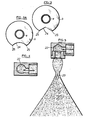
- Figure 2 shows part of the refrigerant according to section II II.
- the exchanger 7 is formed from horizontal tubes with fins, at least partly circular, occupying the entire surface of the enclosure.
- an element 12 of the exchanger through which the fluid to be cooled, consists of a tube formed by four sections of finned tubes, parallel in the vertical plane (FIG. 1) and offset horizontally as shown for tubes 13, 14, 15, 16 ( Figure 2).
- the invention can also be applied to other configurations.
- the sections of finned tubes are arranged one above the other. These sections are connected to each other by elbows welded at their ends.
- the hot fluid arrives in a distributor (not shown) to which the inlets are connected in parallel upper 17 of elements 12, 18, 19, etc.
- the cooled fluid is recovered in a collector (not shown) on which the lower outlets 20 of the preceding elements are connected.
- the cooling water coming from the recovery tank is sent into ramps 8 provided at regular intervals with sprayers 21 producing a cone of droplets uniformly distributed throughout the horizontal section. This is achieved by unusual operation of the sprayers and allows uniform cooling of the tubes in the droplet line.
- sprayers used in refrigerants, produce a cone of droplets in which they are distributed in a ring leaving an interior area almost dry.
- sprayers at the outlet of which a mobile element carrying helical grooves allows the formation of a cone of uniformly distributed droplets.
- a known sprayer represented in FIGS. 4 and 5, comprising a swirl chamber 22, gives, for a pressure drop in the sprayer of 0.75 bar, a hollow conical envelope of fine droplets.
- the droplet cone allows uniform and efficient cooling of the fin tubes with low water consumption.
- FIG. 3A Another arrangement taken to increase the efficiency of the exchanger is the notching of the lower part of the circular fins of the tubes.
- the three upper rows of finned tubes have modified fins.
- Figure 3 shows in section a tube with a fin notched in its lower part.
- the notch 24 has an angular profile in the embodiment illustrated in Figure 3.
- Other profiles could be provided.
- the notch 24 has a curved profile, for example substantially circular.
- the cooling water droplets properly wet the upper row (or first row) of finned tubes. Owing to the small space separating the fins of two neighboring tubes of the same horizontal row, the second row is only slightly affected by the droplets and receives almost only the runoff water coming from the upper row. The phenomenon is reproduced a fortiori for the third and fourth rows. In order for the water to pass from the fins of a hot tube of a row to the fins of a less hot tube adjacent to an immediately lower row, the droplets which stream on the fins come together in the form of drops at the ends of notch and fall on the fins of the tubes next to the next lower row.
- the notch 24 must be such that its ends 25 (projection formed by the connection between the peripheral circular part of the fin and the notch) are plumb with the fins of the corresponding lower tubes and in vertical projection, between the wall of the tube (a) and the edge of the fin (b).
- the dimensions of the fins and their notch are however dependent on the compactness of the exchanger which is defined to allow air circulation under low pressure without significant pressure drop.
- the treatment station 11 comprises means for metering the acidity of the cooling water admitted by the compensation circuit 10 and for controlled discharge of the recycled cooling water.
- This rejection controlled by a valve 30 makes it possible to eliminate the water too loaded with salts.
- the supply of treated water makes it possible to compensate for the flow of evaporated water and the flow of deconcentration.
- the exchanger has four horizontal rows of tubes, but it may have only two or three rows, the choice being determined by the amount of heat to be removed.
- the exchanger consists of elements comprising four sections of finned tubes arranged according to FIG. 2.
- the central tube has an outside diameter of approximately 25.4 mm (1 inch) and the fins, about 57 mm,
- the tubes are distant in horizontal projection of 65 mm and in vertical projection, of 55 mm.
- the cord subtended by the notch is 25 mm and the distance from its central part to the center of the tube, 17 mm.
- the speed of the air delivered by the fans is between 2 and 6-m / s.
- the air inlet temperature is 15 to 25 ° C and the humid air outlet temperature is 25 to 30 ° C.
- the cooling water consumption per m2 of front surface of the exchanger (i.e. perpendicular to the air flow) is:
- the evacuated thermal power is from 70 to 80 KW m- 2 .
- the exchange coefficient is multiplied by two, without modifying the pressure drops.
Landscapes
- Engineering & Computer Science (AREA)
- Physics & Mathematics (AREA)
- Thermal Sciences (AREA)
- Mechanical Engineering (AREA)
- General Engineering & Computer Science (AREA)
- Geometry (AREA)
- Heat-Exchange Devices With Radiators And Conduit Assemblies (AREA)
Applications Claiming Priority (2)
| Application Number | Priority Date | Filing Date | Title |
|---|---|---|---|
| FR8304567 | 1983-03-21 | ||
| FR8304567A FR2543282A1 (fr) | 1983-03-21 | 1983-03-21 | Refrigerant ferme a ventilation forcee et a circuit etanche |
Publications (2)
| Publication Number | Publication Date |
|---|---|
| EP0119934A2 true EP0119934A2 (de) | 1984-09-26 |
| EP0119934A3 EP0119934A3 (de) | 1985-04-24 |
Family
ID=9287052
Family Applications (1)
| Application Number | Title | Priority Date | Filing Date |
|---|---|---|---|
| EP84400569A Withdrawn EP0119934A3 (de) | 1983-03-21 | 1984-03-21 | Zwangsbelüfteter Kühler mit geschlosssenem und dichtem Kreislauf |
Country Status (2)
| Country | Link |
|---|---|
| EP (1) | EP0119934A3 (de) |
| FR (1) | FR2543282A1 (de) |
Cited By (6)
| Publication number | Priority date | Publication date | Assignee | Title |
|---|---|---|---|---|
| FR2693262A1 (fr) * | 1992-07-03 | 1994-01-07 | Sts | Dispositif de refroidissement d'un liquide par un fluide tel que de l'air. |
| EP0687878A1 (de) * | 1994-06-15 | 1995-12-20 | BDAG Balcke-Dürr Aktiengesellschaft | Verdunstungskühlturm |
| AU765388B2 (en) * | 2000-09-22 | 2003-09-18 | Baltimore Aircoil Company, Incorporated | Circuiting arrangement for a closed circuit cooling tower |
| EP1439361A1 (de) * | 2003-01-15 | 2004-07-21 | Air Tech. Co., Ltd. | Verdampfungswärmetauscher mit Profilierten Rohren mit wenigen oder ohne Rippen |
| WO2012009221A3 (en) * | 2010-07-16 | 2012-04-26 | Evapco, Inc. | Evaporative heat exchange apparatus with finned elliptical tube coil assembly |
| WO2013026223A1 (zh) * | 2011-08-19 | 2013-02-28 | Zhang Hongsheng | 一种高温水的消热器 |
Families Citing this family (1)
| Publication number | Priority date | Publication date | Assignee | Title |
|---|---|---|---|---|
| CN106767014A (zh) * | 2017-01-12 | 2017-05-31 | 中化重庆涪陵化工有限公司 | 复合肥淋浴式冷却装置 |
Family Cites Families (9)
| Publication number | Priority date | Publication date | Assignee | Title |
|---|---|---|---|---|
| BE500083A (de) * | ||||
| GB191316582A (en) * | 1913-07-19 | 1914-06-25 | Walter Sydney Tyler | Improvements in or relating to Radiators of the Gilled-tube Type. |
| FR618988A (fr) * | 1926-06-29 | 1927-03-24 | Tuyère pulvérisatrice de liquides | |
| FR1027821A (fr) * | 1950-11-17 | 1953-05-15 | Condenseur à air | |
| GB845844A (en) * | 1959-02-11 | 1960-08-24 | Gea Luftkuhler Gesselschaft M | Evaporating cooling plant |
| US3384165A (en) * | 1966-02-03 | 1968-05-21 | Du Pont | Heat exchanger |
| US3791634A (en) * | 1970-04-29 | 1974-02-12 | P Phelps | Cross flow tower fill of cellular construction |
| US3870485A (en) * | 1972-03-06 | 1975-03-11 | Japan Gasoline | Cooling tower |
| GB2076517B (en) * | 1980-05-22 | 1985-04-03 | Tokyo Shibaura Electric Co | Modifying heat exchange in tubular heat exchangers |
-
1983
- 1983-03-21 FR FR8304567A patent/FR2543282A1/fr not_active Withdrawn
-
1984
- 1984-03-21 EP EP84400569A patent/EP0119934A3/de not_active Withdrawn
Cited By (7)
| Publication number | Priority date | Publication date | Assignee | Title |
|---|---|---|---|---|
| FR2693262A1 (fr) * | 1992-07-03 | 1994-01-07 | Sts | Dispositif de refroidissement d'un liquide par un fluide tel que de l'air. |
| EP0687878A1 (de) * | 1994-06-15 | 1995-12-20 | BDAG Balcke-Dürr Aktiengesellschaft | Verdunstungskühlturm |
| AU765388B2 (en) * | 2000-09-22 | 2003-09-18 | Baltimore Aircoil Company, Incorporated | Circuiting arrangement for a closed circuit cooling tower |
| EP1439361A1 (de) * | 2003-01-15 | 2004-07-21 | Air Tech. Co., Ltd. | Verdampfungswärmetauscher mit Profilierten Rohren mit wenigen oder ohne Rippen |
| WO2012009221A3 (en) * | 2010-07-16 | 2012-04-26 | Evapco, Inc. | Evaporative heat exchange apparatus with finned elliptical tube coil assembly |
| CN103080687A (zh) * | 2010-07-16 | 2013-05-01 | 艾威普科公司 | 具有翅片椭圆管线圈组件的蒸发热交换装置 |
| WO2013026223A1 (zh) * | 2011-08-19 | 2013-02-28 | Zhang Hongsheng | 一种高温水的消热器 |
Also Published As
| Publication number | Publication date |
|---|---|
| FR2543282A1 (fr) | 1984-09-28 |
| EP0119934A3 (de) | 1985-04-24 |
Similar Documents
| Publication | Publication Date | Title |
|---|---|---|
| EP0010118B1 (de) | Wärmeaustauscher, insbesondere für atmosphärische Kühler | |
| WO2019150061A1 (fr) | Dispositif de regulation de temperature d'une batterie ou d'un dispositif electronique de puissance | |
| EP0491821B1 (de) | Verfahren und anlage zur erzeugung von trinkwasser aus belastetem wasser | |
| EP0890803B1 (de) | Wassererhitzer mit doppelter Kammer zur direkten Wärmeübertragung | |
| EP3973581B1 (de) | Batterie mit einer temperaturregulierungsvorrichtung unter verwendung einer dielektrischen flüssigkeit | |
| EP0077715B1 (de) | Modultrockner zum Trocknen von Getreide | |
| WO2018019865A1 (fr) | Echangeur de chaleur a tubes verticaux et procede d'echange de chaleur | |
| FR2543282A1 (fr) | Refrigerant ferme a ventilation forcee et a circuit etanche | |
| EP0151547B1 (de) | Atmosphärischer Kühler mit verminderten Wasserdampffahnen | |
| CN114046674B (zh) | 一种采用搪玻璃翅片管的闭式冷却塔 | |
| FR2565337A1 (fr) | Refrigerant a point de rosee | |
| EP0093638B1 (de) | Fraktioniertes Destillationsverfahren und Anwendung für die Herstellung von thermischer und mechanischer Energie aus zwei Wärmequellen auf niedrigem Niveau | |
| FR2591504A1 (fr) | Procede d'evaporation-condensation de films ruisselants, elements pour sa mise en oeuvre et ses applications. | |
| BE504253A (de) | ||
| CN214270271U (zh) | 污水处理喷嘴结构及其污水处理设备 | |
| CN210486571U (zh) | 一种节水型切换式自然通风冷却塔 | |
| FR2850122A1 (fr) | Dispositif d'extraction de l'eau presente dans l'air par condensation | |
| KR102099856B1 (ko) | 냉각장치 | |
| EP3113856B1 (de) | Destillationsvorricthung durch polarisation und nebulisation in einer elektrostatischen flasche | |
| FR2484070A1 (fr) | Echangeur de chaleur perfectionne a condensation | |
| FR3107785A1 (fr) | Dispositif de régulation thermique pour un ou plusieurs composants électriques, notamment pour une ou plusieurs cellules de stockage d’énergie d’une batterie | |
| EP0354892A1 (de) | Wärmeaustauscher zwischen einem Gas und einer Flüssigkeit mit erhöhten thermischen Austauschfähigkeiten | |
| WO2025141256A1 (fr) | Installation et procédé de désalinisation d'eau de mer par évaporation utilisant l'énergie solaire | |
| FR2510734A1 (fr) | Ensemble refroidisseur et epurateur a eau utilisable en association avec un evaporateur de pompe a chaleur | |
| BE1002337A6 (fr) | Echangeur de chaleur entre un gaz et un fluide a pouvoir d'echange thermique eleve. |
Legal Events
| Date | Code | Title | Description |
|---|---|---|---|
| PUAI | Public reference made under article 153(3) epc to a published international application that has entered the european phase |
Free format text: ORIGINAL CODE: 0009012 |
|
| AK | Designated contracting states |
Designated state(s): AT BE CH DE FR GB IT LI LU NL SE |
|
| PUAL | Search report despatched |
Free format text: ORIGINAL CODE: 0009013 |
|
| AK | Designated contracting states |
Designated state(s): AT BE CH DE FR GB IT LI LU NL SE |
|
| STAA | Information on the status of an ep patent application or granted ep patent |
Free format text: STATUS: THE APPLICATION IS DEEMED TO BE WITHDRAWN |
|
| 18D | Application deemed to be withdrawn |
Effective date: 19851225 |
|
| RIN1 | Information on inventor provided before grant (corrected) |
Inventor name: BLONDEAU, MICHEL HONORE Inventor name: VIANNAY, STEPHANE GEORGES JEAN-MARIE Inventor name: JANNOT, MARCEL AUGUSTIN JOSEPH |