EP0119960B1 - Armature-connecteur pour installations sanitaires - Google Patents
Armature-connecteur pour installations sanitaires Download PDFInfo
- Publication number
- EP0119960B1 EP0119960B1 EP19840810120 EP84810120A EP0119960B1 EP 0119960 B1 EP0119960 B1 EP 0119960B1 EP 19840810120 EP19840810120 EP 19840810120 EP 84810120 A EP84810120 A EP 84810120A EP 0119960 B1 EP0119960 B1 EP 0119960B1
- Authority
- EP
- European Patent Office
- Prior art keywords
- fitting
- water
- battery piece
- housing
- connecting device
- Prior art date
- Legal status (The legal status is an assumption and is not a legal conclusion. Google has not performed a legal analysis and makes no representation as to the accuracy of the status listed.)
- Expired
Links
Images


Classifications
-
- E—FIXED CONSTRUCTIONS
- E03—WATER SUPPLY; SEWERAGE
- E03C—DOMESTIC PLUMBING INSTALLATIONS FOR FRESH WATER OR WASTE WATER; SINKS
- E03C1/00—Domestic plumbing installations for fresh water or waste water; Sinks
- E03C1/02—Plumbing installations for fresh water
- E03C1/04—Water-basin installations specially adapted to wash-basins or baths
- E03C1/042—Arrangements on taps for wash-basins or baths for connecting to the wall
-
- F—MECHANICAL ENGINEERING; LIGHTING; HEATING; WEAPONS; BLASTING
- F16—ENGINEERING ELEMENTS AND UNITS; GENERAL MEASURES FOR PRODUCING AND MAINTAINING EFFECTIVE FUNCTIONING OF MACHINES OR INSTALLATIONS; THERMAL INSULATION IN GENERAL
- F16K—VALVES; TAPS; COCKS; ACTUATING-FLOATS; DEVICES FOR VENTING OR AERATING
- F16K11/00—Multiple-way valves, e.g. mixing valves; Pipe fittings incorporating such valves
- F16K11/02—Multiple-way valves, e.g. mixing valves; Pipe fittings incorporating such valves with all movable sealing faces moving as one unit
- F16K11/06—Multiple-way valves, e.g. mixing valves; Pipe fittings incorporating such valves with all movable sealing faces moving as one unit comprising only sliding valves, i.e. sliding closure elements
- F16K11/072—Multiple-way valves, e.g. mixing valves; Pipe fittings incorporating such valves with all movable sealing faces moving as one unit comprising only sliding valves, i.e. sliding closure elements with pivoted closure members
- F16K11/074—Multiple-way valves, e.g. mixing valves; Pipe fittings incorporating such valves with all movable sealing faces moving as one unit comprising only sliding valves, i.e. sliding closure elements with pivoted closure members with flat sealing faces
- F16K11/0746—Multiple-way valves, e.g. mixing valves; Pipe fittings incorporating such valves with all movable sealing faces moving as one unit comprising only sliding valves, i.e. sliding closure elements with pivoted closure members with flat sealing faces with two or more closure plates comprising a single lever control
-
- F—MECHANICAL ENGINEERING; LIGHTING; HEATING; WEAPONS; BLASTING
- F16—ENGINEERING ELEMENTS AND UNITS; GENERAL MEASURES FOR PRODUCING AND MAINTAINING EFFECTIVE FUNCTIONING OF MACHINES OR INSTALLATIONS; THERMAL INSULATION IN GENERAL
- F16K—VALVES; TAPS; COCKS; ACTUATING-FLOATS; DEVICES FOR VENTING OR AERATING
- F16K19/00—Arrangements of valves and flow lines specially adapted for mixing fluids
-
- F—MECHANICAL ENGINEERING; LIGHTING; HEATING; WEAPONS; BLASTING
- F16—ENGINEERING ELEMENTS AND UNITS; GENERAL MEASURES FOR PRODUCING AND MAINTAINING EFFECTIVE FUNCTIONING OF MACHINES OR INSTALLATIONS; THERMAL INSULATION IN GENERAL
- F16K—VALVES; TAPS; COCKS; ACTUATING-FLOATS; DEVICES FOR VENTING OR AERATING
- F16K27/00—Construction of housing; Use of materials therefor
- F16K27/04—Construction of housing; Use of materials therefor of sliding valves
- F16K27/044—Construction of housing; Use of materials therefor of sliding valves slide valves with flat obturating members
- F16K27/045—Construction of housing; Use of materials therefor of sliding valves slide valves with flat obturating members with pivotal obturating members
Definitions
- the invention relates to a sanitary fitting connection element with cold and hot water connection piece with a housing and a battery piece held therein for receiving a fitting, in particular a mixer tap, with separate cold and hot water channels in the battery piece in the fitting.
- Known fittings are designed in such a way that the flush-mounted pipelines used for the separate supply of cold and hot water are fed to a surface-mounted fitting, from which the water is fed, if necessary, to a mixer tap which subsequently flows through an outlet.
- the supply lines to the fittings for the cold and hot water are taken from two main lines. This requires line crossings and, depending on the local conditions, relatively long lines.
- the connections of commercially available fittings are also designed such that the feed lines to the fittings have to assume certain positions so that the outlet connection can be installed in the correct position, such that, for example, the outlet is directed exactly downwards.
- a fitting with a mixing valve is known from US-A3674048, in which the cold and hot water supply lines open into a common mixing room.
- a rotatable valve body first releases the cold water supply opening and then the hot water supply opening. If the cold and hot water supply lines are swapped to avoid line crossings, the valve body can be inserted into the housing rotated by 180 °.
- the object is to be achieved to create a fitting connection element for sanitary installations, in which cold and hot water connection allows a simplified, cross-free line routing, the housing accommodating the fitting with the connecting piece being in any rotational position by one Wall can take a right-angled axis and the mixed water outlet can still be directed downwards.
- the invention with which this object is achieved is characterized in that the fitting rotatably engages in a hole in the battery piece, that cold and hot water in the fitting are in flow connection via a respective entry opening with cavities of the battery piece, and one each Cavity is connected to the cold or hot water supply, the mutually sealed inlet openings in the axial direction - with respect to the longitudinal axis of the battery piece - are staggered and the inlet openings in the mutually separated longitudinal channels of the valve in any rotational position with the keep separate cavities of the battery piece in connection.
- valve connection elements can also be designed with continuous channels, so that a line-free connection from valve to valve is possible.
- Another variant is to provide additional channels for the mixed water connection of a foot shower and a shower.
- connection piece 11 is used to connect a cold and hot water supply line 8, 9.
- the water is supplied to each fitting through connection stub 11.
- the tubes 8, 9 are surrounded by protective tubes 17, which also provide thermal insulation.
- the tight connection of the tubes 8, 9 with the connection piece 11 is made by detachable union screw connections 10. Both connection pieces 11 are integrating parts of a sleeve-shaped, partially hollow battery piece 4.
- this battery piece 4 contains in its interior two cavities 12, 14, each of which is in flow connection with one of the connecting pieces 11. Cavities 12, 14 are liquid-separated from one another and extend axially offset with respect to the bore 19 of the essentially cylindrical battery piece 4. Thus, the cold and hot water in this battery piece 4 are guided separately and cannot mix.
- the two cavities 12, 14 each have an opening 45, 47 opening into the bore 19, which are offset from one another in the axial direction.
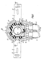
- the battery piece 4 is surrounded by a housing 5 which can be used for surface or flush mounting.
- a pipe section 15 of the battery piece 4 with an reduced outside diameter protrudes from the housing 5 and penetrates a pressure ring 1 on the front side.
- the housing 5 and the battery piece 4 there are two soundproof shells 3 made of rubber-elastic material, for example made of rubber or a foamed plastic. These two soundproofing shells 3 are inserted into a housing bore 25 and can be separated along a separating joint 18 running parallel to the front face of the housing, so that the rear shell is inserted during assembly, then the battery piece 4 is inserted and the front shell is then placed on.
- the pressure piece 1 presses the battery piece 4 in the housing 5 with the aid of screws 44.
- the pressure rings 1 rests on the shoulders of the housing 5.
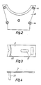
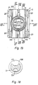
- the housing 5 is flush-mounted by two opposing individual fastening tabs 2 to a wall or the like. These fastening tabs 2 contain oblong holes 21 which run transversely to one another. Each of these fastening tabs 2 is provided with a transversely projecting arch piece 22, which engages in an annular groove 20 of the housing 5, as shown in FIG. This annular groove 20 opens against the front of the housing; a second coaxial annular groove 20 opens against the rear of the housing, so that the fastening tabs 2 can be used either at the front or the rear.
- the fastening tabs 2 are held on the housing 5 with the aid of screws 24 which engage in corresponding threaded holes in the housing 5.
- the annular groove 20 is provided with cams 27, which are present at intervals of 30 ° or 45 ° and engage in corresponding recesses in the fastening tabs 2. In this way, the position of the fastening tabs 2 can be precisely adapted to the local conditions. At most, only a single fastening tab 2 can be used.
- FIG. 1 it is also possible to provide a fastening ring 41 instead of individual fastening lugs 2 engaging in an annular groove 20, from which two lugs 2 with elongated holes 21 protrude in one piece radially on a diametrically opposite side.
- this fastening ring can be fastened in predetermined different angular positions by screws 24 on the front or rear end face of the housing 5.
- the battery piece can also be pulled out of the housing 5 to connect plastic pipes to the connecting pieces.
- the housing can be made of either metal or plastic.
- the tubes 8, 9 can either consist of metal, in particular copper or plastic.
- the pipes 8, 9 are thus exposed, are accessible from the front and can be connected to or detached from the connecting piece 11 by loosening or screwing in the screw nut 10 without the housing 5 needs to be expanded.
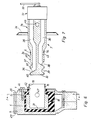
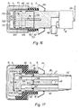
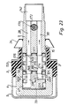
- An outlet fitting 7 according to FIG. 7 is inserted into the bore 19 of the battery piece 4.
- This contains a plug-in part 7a engaging in the bore 19 and a cylindrical body 7b lying above the plaster, in which there are two longitudinal channels 28, 30.
- In the plug-in part 7a there is a first entry opening 36 for the longitudinal channel 28 and a diametrically opposite second entry opening 38 for the Longitudinal channel 30.
- Each of these two inlet openings 36, 38 opens into an annular groove 37, 39 in the plug-in part 7a.
- These inlet openings 36, 38 and thus also the annular grooves 37, 39 are offset from one another in the axial direction of the fitting 7.
- the annular grooves 37, 39 are in communicating connection with the openings 45, 47 and thus also with the cavities 12, 14.
- the annular grooves 37, 39 are sealed off from one another by sealing rings 40, in particular O-rings, in the bore 19, as a result of which reliable liquid separation between the cold and the warm water is ensured.
- Another - preferably flat - sealing ring 6 is located at the outer end of the plug-in part 7a.
- the detachable fastening of the inserted fitting 7, which is rotatable relative to the battery piece 4, is carried out by one or more locking screws 42 which engage on the periphery of the fitting and which engage obliquely in an annular groove 43 of the fitting 7.
- a longitudinally displaceable cover rosette 34 which can be brought into abutment against a wall or the like, is attached to the cylindrical part 7b of the fitting 7 protruding from the battery piece 4.
- the outer end of the fitting 7 is connected to a mixing valve 32, in which the cold and hot water flows are mixed in accordance with the temperature that can be set on a lever 22 or handwheel.
- This mixing valve 32 is of known design and is therefore not explained in detail here.
- the mixed water leaves the fitting 7 through a downward opening 49, whereby the same lever can also be used for opening and closing.
- An embodiment variant consists in that instead of ring grooves 37, 39 in the plug-in part 7a of the fitting 7, such ring grooves arranged in the axial direction are arranged in the bore 19 of the battery piece.
- the short extension 58 of the insert sleeve 50 which engages in the opening of the connecting piece 11 has a non-circular cross section on the outside, preferably in the form of a hexagon or Octagons.
- the use of a hexagon or octagon to avoid twisting the tube when tightening the screw connection is known per se from US-A-3 408 099.
- the counterpart that is, the opening in the connecting piece 11, has an opposite, non-circular cross-sectional shape. Since the plastic pipes 8, 9 are somewhat flexible, the screw connection can also be carried out after the rigid attachment of the housing 5, or the pipes 8, 9 can be easily replaced during repairs without the housing 5 having to be removed, which in the case of a flush-mounted version has a large size would be connected.
- FIG. 11 shows the pipe connection when using metallic pipes, in particular copper pipes 8a, 9a.
- the pipe ends are soldered to a metal sleeve 61 here.
- a sealing ring 56 Between the end face 64 of this metal sleeve 61 and the end face 62 of the connecting piece 11 there is a sealing ring 56, preferably an O-ring.
- the screw connection is carried out by means of a union nut 10 placed on the thread 60 of the connecting piece, which lies against a shoulder of the metal sleeve 60.
- the same connecting piece 11 can be used for both plastic pipes and metal pipes, which simplifies storage.
- the battery piece 4 has two outlet ports 13 and two outlet ports 13, so that both the cold water and the hot water can be passed on separately, for example to a next valve. So that the separate flow of the cold and warm water around the bore 19 can take place, the cavities 12, 14 are elongated in cross-section and each extend in an arc between the inlet and outlet ports 11, 13. Otherwise, the structure and operation correspond to those according to the embodiment according to Figures 1-8, wherein the same reference numerals mean the same parts.
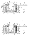
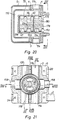
- FIGS. 14-18 there is a water connection in a battery piece 4 at an inlet connection 114 and leads via a channel 110 to an outlet connection 116, as can be seen from FIG. 14.
- the other water connection opens at an inlet nozzle 118 and leads via a channel 112 to an outlet nozzle 120, as shown in FIG. 15.
- these two channels 110, 112 are separated by a partition wall 22 and opposite one another the bore 19 is closed by a bottom 31.
- the housing 5 is suitable for flush mounting and serves to accommodate a battery piece 4. Between the housing 5 and the battery piece 4, a soundproofing insert 3 is attached, for example made of soft rubber or foam plastic.
- a cylindrical distributor 73 is arranged, which is located in the cylindrical cavity 19 of the essentially cylindrical battery piece 4 and can be rotated relative thereto.
- the fitting 7 With a thread 15 at the open end of the battery piece 4, the fitting 7 is screwed, which is connected to a known mixing valve 32, not shown, which is inserted into a central bore 142 and is adjustable by a lever 22.
- An outlet nozzle 48 is inserted into a downward outlet opening 49.
- a rosette 34 which is longitudinally displaceable on the fitting 7 serves to cover the opening on the wall side of the fitting part located above the plaster.
- the two inlet sockets 114 and 118 are parallel next to each other and the two outlet sockets 116, 120 are also parallel next to each other and are located on diametrically opposite sides with respect to the bore 19.
- the inlet and outlet ports assigned to the cold water run coaxially; also the inlet and outlet connections for hot water.
- the channels 110, 112 run in a U-shape around the bottom 31 of the battery piece 4.
- the two inlet openings 45 and 47 are in Axial direction offset from each other.
- the distributor 73 can thus assume any rotational position relative to the battery piece 4 and thus also to the housing 5.
- Pipes for a next fitting can be connected directly to the outlet nozzles 116 and 120 without the need to cross the lines. This is achieved in that the distributor 73 can be rotated in the bore 19 and can optionally also assume a position rotated by half a turn relative to the fitting 7. This makes it irrelevant whether the hot water supply is to be supplied on the left or right side of the next fitting.
- the outlet opening 49 can always be directed vertically downward regardless of the angular position of the housing 5.
- the hot water supply is always on the left and the cold water is always on the right, as prescribed by installation standards and given by the structure of the mixing valve 32.
- connection device As a result, it does not matter whether the cold or hot water pipe is fed to the left or right side of the connection device during installation and piping, since the distributor 73 is rotated by 180 °, which leads to the mixing valve 32 Cold and hot water is always on the right side.
- the pipes can be fed to the connection elements at any angle in the wall level, in contrast to conventional fittings.
- slots 20 are also present in the housing 5, which are used to accommodate angular fastening brackets 2 according to FIGS. 3, 4. These slots 20 are arranged either continuously or on opposite sides of the housing, so that these mounting brackets 2 can be used either on the front or rear of the housing 5. Instead of four such mounting brackets 2, only a smaller number of the same can be used.
- FIG. 1 An embodiment variant is shown in FIG.
- the distributor and the fitting 7 ' are made in one piece and held in place by the thread 15 in the cavity 19 of the battery piece 4.
- One longitudinal channel 28 is flow-connected to a chamber 184 via its mouth 190, which is open at the end.
- This chamber 184 is on one side through the end face of the fitting 7 'and on the other Side bounded by the bottom 31.
- the channel 112, which is closed with respect to the chamber 184, is in flow connection via the transverse bore 196 and annular groove 124.
- This fitting 7 ' is sealed off from the cavity 19 by sealing rings 40.
- a transverse bore 194 projecting laterally from the longitudinal channel 28 is closed by a threaded plug 186.
- the second parallel longitudinal channel 30 is closed on the end face by a threaded plug 118, but its transverse bore 196 is open and - as in the exemplary embodiments according to FIGS. 14-18 - opens into the channel 112 via the annular groove 124.
- the threaded plug 186 is removed from the transverse bore 194 and, instead, as indicated by broken lines, is screwed into the transverse bore 28 on the end face, so that it is tightly closed.
- the threaded plug 188 is removed from the longitudinal channel 30 and instead screwed into the transverse bore 196.
- the cold and hot water channels leading to the mixer tap are interchanged.
- the same can be achieved by using two different distributor fittings 7 ', which can optionally be used in the cavity 19, in which the open and closed channels or transverse bores are interchanged.
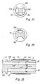
- FIGS. 20-25 an embodiment variant is shown, which additionally has two pipe sockets 156, 158 discharging the mixed water, one of which. for example, can lead to a head shower and the other to a foot shower.
- the same reference numbers here also mean the same parts and the same functions.
- FIGS. 20-25 there is a second drain distributor 153 which is inserted between the first distributor 73 and the fitting 7.
- the separate inflow of hot and cold water to the mixer tap takes place according to FIGS. 20, 21 and 23 through the inlet nozzle 114 and 118.
- the water flowing into the inlet nozzle 114 passes through the inlet opening 47 into the annular groove 126 and from there the drain manifold 153 and its longitudinal bore 178 in the longitudinal channel of the fitting 7.
- the mixed water leaving the mixing valve 32 arrives in the opposite direction to the cold and hot water via a central opening 172 to a conventional changeover valve 170.
- the mixed water flows in from the opening 172 the fitting 7 into the longitudinal bore 165 and the channel 166 of the drain manifold 153. From there it passes through an opening 164 of the wall of the battery piece 4 into a chamber 160 and from here to a connecting piece 156, which is connected via a line, for example a head shower can be connected.
- the valve body 171 closes the longitudinal bore 165, so that afterwards the mixed water into the longitudinal channel 167 of the fitting 7, the channel 168 of the drain manifold 153 and the opening 162 in the wall of the battery piece 4 flows into the chamber 161 and from here into a connection stub 158, for example to a foot shower.
- the two annular grooves 174, 176, into which the channels 166, 168 of the drain distributor 153 open, are offset in the axial direction and the openings 162 and 164 are offset on the circumference and are preferably diametrically opposite.
- FIG. 23 there is an axially separable connection with pin 146 and groove in the counterpart between the distributor 73 and the drain distributor 153.
- the design is such that these two parts can only be joined in two positions rotated by 180 °.
- the distributor 73 and the drain distributor 153 can be rigidly connected to one another with the fitting 7 by a central screw 75, as is shown in FIG. 16.
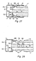
- FIG. 26 shows an embodiment variant in which the drain manifold 153 is dispensed with, but the same functions are possible while maintaining the same dimensions of the battery piece 4 of the housing and the fitting 7 as in connection with FIGS. 17th
- a sleeve 82 which effects the rigid connection is provided at one end with an external thread engaging in the thread 15 of the battery piece 4 and at the other end with an internal thread engaging in the fitting 7.
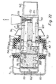
- FIG. 28 shows an embodiment variant which is comparable to that according to FIG. 27, but which is also for connecting a head and foot shower is suitable.
- the distributor and the fitting 7 in turn consist of a single piece which is rotatably held in the bore of the battery piece 4.
- the mode of operation corresponds to that according to FIG. 19, combined with that according to FIGS. 20-25, the same reference numbers denoting the same parts.
- the valve can be designed so that the one longitudinal channel 28 opens out at the rear end face - that is instead of into the annular groove 29.
- the plug-in part 7a can thus be imagined as if it were cut off in the area between the grooves 37 and 39.
- the associated battery piece 4 is provided, similarly to FIGS. 27 and 28, with a chamber arranged on the end face, corresponding to the chamber 184. As a result, only one annular groove 38 is required.
- the distributor 73 can also be formed in that the longitudinal channel 138 (FIG. 17) opens into an end chamber of the battery piece 4 instead of into the annular groove 126.
- the connecting pieces 114, 116, 118, 120, 156, 158 can be designed either as solder connections for copper lines, as threaded connections for galvanic steel pipes or as compression fittings for plastic pipes, as was described in connection with FIGS. 9-11 .
Landscapes
- Engineering & Computer Science (AREA)
- General Engineering & Computer Science (AREA)
- Mechanical Engineering (AREA)
- Health & Medical Sciences (AREA)
- Life Sciences & Earth Sciences (AREA)
- Hydrology & Water Resources (AREA)
- Public Health (AREA)
- Water Supply & Treatment (AREA)
- Domestic Plumbing Installations (AREA)
- Valve Housings (AREA)
Claims (16)
Priority Applications (1)
| Application Number | Priority Date | Filing Date | Title |
|---|---|---|---|
| AT84810120T ATE25757T1 (de) | 1983-03-16 | 1984-03-13 | Sanitaer-armaturanschlussorgan. |
Applications Claiming Priority (6)
| Application Number | Priority Date | Filing Date | Title |
|---|---|---|---|
| CH150283 | 1983-03-16 | ||
| CH1501/83 | 1983-03-16 | ||
| CH150183 | 1983-03-16 | ||
| CH1502/83 | 1983-03-16 | ||
| CH355783 | 1983-06-29 | ||
| CH3557/83 | 1983-06-29 |
Publications (2)
| Publication Number | Publication Date |
|---|---|
| EP0119960A1 EP0119960A1 (fr) | 1984-09-26 |
| EP0119960B1 true EP0119960B1 (fr) | 1987-03-04 |
Family
ID=27173025
Family Applications (1)
| Application Number | Title | Priority Date | Filing Date |
|---|---|---|---|
| EP19840810120 Expired EP0119960B1 (fr) | 1983-03-16 | 1984-03-13 | Armature-connecteur pour installations sanitaires |
Country Status (2)
| Country | Link |
|---|---|
| EP (1) | EP0119960B1 (fr) |
| DE (1) | DE3462543D1 (fr) |
Families Citing this family (16)
| Publication number | Priority date | Publication date | Assignee | Title |
|---|---|---|---|---|
| US4584723A (en) * | 1983-06-29 | 1986-04-29 | Walter Hussauf | Fitting for connecting a plumbing faucet to plumbing pipes |
| EP0205486B1 (fr) * | 1984-12-11 | 1990-01-24 | Gevipi A.G. | Soupape de melange a poignee unique ayant un element sensible a la force hydraulique pour comprimer la cartouche |
| IT1179860B (it) * | 1984-12-11 | 1987-09-16 | Gevipi Ag | Rubinetto miscelatore a cartuccia a monocomando con dispositivo invertitore dell alimentazione |
| DE3501679C1 (de) * | 1985-01-19 | 1986-06-05 | Knebel & Röttger GmbH & Co, 5860 Iserlohn | Auslaufarmatur |
| IT1185805B (it) * | 1985-06-13 | 1987-11-18 | Gevipi Ag | Cartuccia con fondello rimovibile per rubinetto miscelatore a piastrine in materiale duro |
| DE3541986C2 (de) * | 1985-11-28 | 1994-11-10 | Grohe Armaturen Friedrich | Mischbatterie mit einem Befestigungsschaft |
| SE447319B (sv) * | 1985-12-12 | 1986-11-03 | Inor Instrument | Sett att ansluta elektriska kablar till elektrisk utrustning |
| DE3723828A1 (de) * | 1987-07-18 | 1989-01-26 | Grohe Armaturen Friedrich | Anschlussvorrichtung fuer mischarmaturen und verfahren zum anschluss der armatur |
| DE3869890D1 (de) * | 1987-09-09 | 1992-05-14 | Fides Treuhand Gmbh | Sanitaere wasseranschlussanordnung. |
| DE3826008C2 (de) * | 1987-09-09 | 1995-02-02 | Fides Treuhand Gmbh | Anschlußvorrichtung für sanitäre Mischarmaturen |
| WO1993021396A1 (fr) * | 1992-04-16 | 1993-10-28 | Stuart Turner Limited | Douche |
| GB2274583B (en) * | 1992-04-16 | 1995-11-15 | Turner Stuart Ltd | Personal shower system |
| DE4421387B4 (de) * | 1994-06-18 | 2005-04-07 | Grohe Water Technology Ag & Co. Kg | Einlochmischbatterie |
| DE19510414C2 (de) * | 1995-03-24 | 1998-02-12 | Friatec Keramik Kunststoff | Befestigungsanordnung mit einem Installationselement |
| DE19856156A1 (de) * | 1998-12-05 | 2000-06-08 | Grohe Kg Hans | Befestigungsanordnung für sanitäre Bauteile |
| AU2002212855A1 (en) * | 2000-11-02 | 2002-05-15 | Feltonmix Limited | A valving and mixing unit |
Family Cites Families (13)
| Publication number | Priority date | Publication date | Assignee | Title |
|---|---|---|---|---|
| CH358293A (de) * | 1958-02-01 | 1961-11-15 | Metaalbewerkings En Handelsbed | Anschluss für biegsame Rohre |
| DE1217718B (de) * | 1964-10-24 | 1966-05-26 | Walter Rotter | Kalt- und Warmwasser-Mischbatterie |
| FR1451052A (fr) * | 1965-10-22 | 1966-06-24 | Robinetterie mélangeuse double | |
| US3408099A (en) * | 1968-02-05 | 1968-10-29 | Appleton Electric Co | Connector for flexible hosing |
| US3583004A (en) * | 1969-05-19 | 1971-06-08 | Precision Plumbing Prod | Straight-through manifold assembly for hot and cold water faucet pairs arranged back to back |
| US3674048A (en) * | 1970-04-09 | 1972-07-04 | Masco Corp | Mixing valve |
| US3823737A (en) * | 1973-07-26 | 1974-07-16 | American Standard Inc | Adaptor for plumbing fitting |
| US4022242A (en) * | 1976-02-26 | 1977-05-10 | Danfoss A/S | Shower control valve assembly |
| DE2712602A1 (de) * | 1977-03-18 | 1978-09-21 | Rotter Kg | Mischarmatur fuer reihenwaschanlagen |
| CH635179A5 (en) * | 1979-01-11 | 1983-03-15 | Walter Hussauf | Spacing device for pipe installation of a wall-mounted tap assembly |
| DE2930518C2 (de) * | 1979-07-27 | 1983-12-01 | Franz Ing.(Grad.) 5353 Mechernich Brettschneider | Einrichtung zum Anschluß einer Leitungsarmatur |
| US4243063A (en) * | 1979-09-14 | 1981-01-06 | American Standard Inc. | Mixing valve |
| US4362186A (en) * | 1981-02-11 | 1982-12-07 | American Standard Inc. | Sanitary fitting |
-
1984
- 1984-03-13 EP EP19840810120 patent/EP0119960B1/fr not_active Expired
- 1984-03-13 DE DE8484810120T patent/DE3462543D1/de not_active Expired
Also Published As
| Publication number | Publication date |
|---|---|
| DE3462543D1 (en) | 1987-04-09 |
| EP0119960A1 (fr) | 1984-09-26 |
Similar Documents
| Publication | Publication Date | Title |
|---|---|---|
| EP0119960B1 (fr) | Armature-connecteur pour installations sanitaires | |
| EP1261824B1 (fr) | Robinet sanitaire, en particulier mitigeur menager | |
| EP1006242B1 (fr) | Système de robinetteries sanitaires | |
| DE3826064A1 (de) | Anschlussanordnung fuer eine sanitaere mischarmatur | |
| CH692051A5 (de) | Mehrzahl von sanitären Mischarmaturen. | |
| EP0942104B1 (fr) | Robinetterie sanitaire | |
| DE4421387B4 (de) | Einlochmischbatterie | |
| EP0309397B1 (fr) | Dispositif pour raccordement en eau d'installations sanitaires | |
| DE2249449A1 (de) | Anschlussvorrichtung fuer die endoeffnungen von doppelwandigen schlaeuchen | |
| EP0790448B1 (fr) | Armature sanitaire | |
| DE3826008C2 (de) | Anschlußvorrichtung für sanitäre Mischarmaturen | |
| DE10247066B4 (de) | Sanitärarmatur mit Anschlussstück | |
| EP0716255B1 (fr) | Robinet sanitaire | |
| DE3941106A1 (de) | Sanitaere mischbatterie fuer wandanschluss | |
| DE10261798A1 (de) | Sanitärarmatur | |
| DE202011050690U1 (de) | Anschluss- und Spüleinheit für eine Unterputz-Sanitärarmatur | |
| DE2324023C3 (de) | UnterputzanschluBstück für Sanitärarmaturen | |
| DE10234740A1 (de) | Wasserzapfarmatur mit Schlauchbrause | |
| DE2324023A1 (de) | Unterputzanschlusstueck fuer sanitaeranlagen | |
| DE2923231A1 (de) | Vorrichtung zum anschluss von eckventilen an wasserleitungen | |
| DE102014100811A1 (de) | Spül- und Prüfeinheit für eine Sanitärarmatur | |
| DE2712602A1 (de) | Mischarmatur fuer reihenwaschanlagen | |
| DE1110095B (de) | Anschluss einer Mischbatterie an eine unter Druck stehende Kalt- und Warmwasserleitung | |
| DE2950172A1 (de) | System aus elementen fuer zapfleitungen fuer kaltes und heisses wasser | |
| DE8324023U1 (de) | Aus ventilgehaeuse und wasserzaehler bestehende baueinheit |
Legal Events
| Date | Code | Title | Description |
|---|---|---|---|
| PUAI | Public reference made under article 153(3) epc to a published international application that has entered the european phase |
Free format text: ORIGINAL CODE: 0009012 |
|
| AK | Designated contracting states |
Designated state(s): AT BE CH DE FR GB IT LI LU NL SE |
|
| 17P | Request for examination filed |
Effective date: 19841102 |
|
| GRAA | (expected) grant |
Free format text: ORIGINAL CODE: 0009210 |
|
| AK | Designated contracting states |
Kind code of ref document: B1 Designated state(s): AT BE CH DE FR GB IT LI LU NL SE |
|
| REF | Corresponds to: |
Ref document number: 25757 Country of ref document: AT Date of ref document: 19870315 Kind code of ref document: T |
|
| REF | Corresponds to: |
Ref document number: 3462543 Country of ref document: DE Date of ref document: 19870409 |
|
| ITF | It: translation for a ep patent filed | ||
| ET | Fr: translation filed | ||
| PLBE | No opposition filed within time limit |
Free format text: ORIGINAL CODE: 0009261 |
|
| STAA | Information on the status of an ep patent application or granted ep patent |
Free format text: STATUS: NO OPPOSITION FILED WITHIN TIME LIMIT |
|
| 26N | No opposition filed | ||
| ITTA | It: last paid annual fee | ||
| PGFP | Annual fee paid to national office [announced via postgrant information from national office to epo] |
Ref country code: SE Payment date: 19920212 Year of fee payment: 9 |
|
| PGFP | Annual fee paid to national office [announced via postgrant information from national office to epo] |
Ref country code: FR Payment date: 19920213 Year of fee payment: 9 |
|
| PGFP | Annual fee paid to national office [announced via postgrant information from national office to epo] |
Ref country code: LU Payment date: 19920220 Year of fee payment: 9 Ref country code: BE Payment date: 19920220 Year of fee payment: 9 |
|
| PGFP | Annual fee paid to national office [announced via postgrant information from national office to epo] |
Ref country code: GB Payment date: 19920302 Year of fee payment: 9 |
|
| PGFP | Annual fee paid to national office [announced via postgrant information from national office to epo] |
Ref country code: NL Payment date: 19920331 Year of fee payment: 9 |
|
| EPTA | Lu: last paid annual fee | ||
| PG25 | Lapsed in a contracting state [announced via postgrant information from national office to epo] |
Ref country code: LU Free format text: LAPSE BECAUSE OF NON-PAYMENT OF DUE FEES Effective date: 19930313 Ref country code: GB Effective date: 19930313 |
|
| PG25 | Lapsed in a contracting state [announced via postgrant information from national office to epo] |
Ref country code: SE Effective date: 19930314 |
|
| PG25 | Lapsed in a contracting state [announced via postgrant information from national office to epo] |
Ref country code: BE Effective date: 19930331 |
|
| BERE | Be: lapsed |
Owner name: HUSSAUF WALTER Effective date: 19930331 |
|
| PG25 | Lapsed in a contracting state [announced via postgrant information from national office to epo] |
Ref country code: NL Effective date: 19931001 |
|
| GBPC | Gb: european patent ceased through non-payment of renewal fee |
Effective date: 19930313 |
|
| NLV4 | Nl: lapsed or anulled due to non-payment of the annual fee | ||
| PG25 | Lapsed in a contracting state [announced via postgrant information from national office to epo] |
Ref country code: FR Effective date: 19931130 |
|
| REG | Reference to a national code |
Ref country code: FR Ref legal event code: ST |
|
| EUG | Se: european patent has lapsed |
Ref document number: 84810120.0 Effective date: 19931008 |
|
| REG | Reference to a national code |
Ref country code: CH Ref legal event code: PUE Owner name: ARMATURENFABRIK WALLISELLEN AG |
|
| REG | Reference to a national code |
Ref country code: CH Ref legal event code: PUEA Free format text: ARMATURENFABRIK WALLISELLEN AG TRANSFER- GEBERIT TECHNIK AG;ARMATURENFABRIK WALLISELLEN AG Ref country code: CH Ref legal event code: NV Representative=s name: ISLER & PEDRAZZINI AG |
|
| PGFP | Annual fee paid to national office [announced via postgrant information from national office to epo] |
Ref country code: CH Payment date: 20010118 Year of fee payment: 18 |
|
| PGFP | Annual fee paid to national office [announced via postgrant information from national office to epo] |
Ref country code: AT Payment date: 20010327 Year of fee payment: 18 |
|
| PGFP | Annual fee paid to national office [announced via postgrant information from national office to epo] |
Ref country code: DE Payment date: 20010426 Year of fee payment: 18 |
|
| PG25 | Lapsed in a contracting state [announced via postgrant information from national office to epo] |
Ref country code: AT Free format text: LAPSE BECAUSE OF NON-PAYMENT OF DUE FEES Effective date: 20020313 |
|
| PG25 | Lapsed in a contracting state [announced via postgrant information from national office to epo] |
Ref country code: LI Free format text: LAPSE BECAUSE OF NON-PAYMENT OF DUE FEES Effective date: 20020331 Ref country code: CH Free format text: LAPSE BECAUSE OF NON-PAYMENT OF DUE FEES Effective date: 20020331 |
|
| PG25 | Lapsed in a contracting state [announced via postgrant information from national office to epo] |
Ref country code: DE Free format text: LAPSE BECAUSE OF NON-PAYMENT OF DUE FEES Effective date: 20021001 |
|
| REG | Reference to a national code |
Ref country code: CH Ref legal event code: PL |